moduweb vision - sauter · moduweb vision collects the log data from the connected devices,...
TRANSCRIPT

moduWeb Vision
7010083003 A 1/101
SAUTER EY-modulo 5moduWeb Vision web operation
Manual7010083003

moduWeb Vision
2/101 7010083003 A2/101 7010083003 A
Contents
1. Preface 51.1 What is moduWeb Vision? 5
2. About this manual 72.1 Purpose and intended readership 72.2 How the manual is structured 72.3 Abbreviations 72.4 Symbols and terms used in this manual 82.5 Illustrations in this manual 8
3. Safety information 93.1 Notes on installation 93.2 Intended use 93.3 Disclaimer 103.4 Standards and directives 10
4. Other applicable documents 11
5. Operation 135.1 Supported browsers 135.2 Starting moduWeb Vision, logging in and out 135.2.1 Calling the application 135.2.2 Login 145.2.3 Welcome screen 145.2.4 Logging out / closing moduWeb Vision 155.2.5 Duration of a moduWeb session 155.3 Main elements in moduWeb Vision 165.4 User interface 165.4.1 Logging out 165.4.2 About 175.4.3 Languages 175.4.4 Status indicator 175.4.5 Main menu, menu tree 185.4.6 Tabs 185.4.7 Breadcrumb navigation (trail) 185.4.8 Navigation tree for plant overview 185.4.9 Content area 185.4.10 Filters 185.5 Menu overview 195.5.1 Main “Info” menu 195.5.2 Main “Settings” menu 195.5.3 Main “Extras” menu 20
6. Plant overview 216.1 List view 21
7. Alarms 257.1 Definition of terms 257.1.1 Alarm/error messages 257.1.2 Alarm priority 267.1.3 Alarm status 267.1.4 Changes of status 267.1.5 Acknowledgement 277.1.6 Notification 277.1.7 Timestamp 277.1.8 Alarm history 277.1.9 Grouped view 287.1.10 Flat view 29
8. Devices 318.1 Device and object list 318.2 Device details 32

moduWeb Vision
7010083003 A 3/1017010083003 A 3/101
8.3 Object details 32
9. Charts 359.1 Combined charts 359.2 Simple charts / logs 37
10. Audit trail 41
11. Scheduling 4311.1 Schedules 4311.1.1 Weekly schedule and exception schedule 4311.1.1.1 Weekly schedule 4511.1.1.2 Exception schedule 4511.1.2 General information 4711.1.3 Adding and deleting data points 4711.1.4 Exporting schedules 4911.2 Calendar 5011.2.1 Calendar view 5011.2.2 Agenda view 5211.2.3 Exporting calendar entries 52
12. Chart settings 5512.1 Simple charts / Logs 5512.2 Combined charts 57
13. Device registration 61
14. Plant structure editor 6314.1 Object types 6414.2 Visualisation structure 68
15. Settings 7115.1 User management 7115.1.1 Roles (user groups) 7115.1.2 Creating a new user 7215.1.3 Editing users 7615.1.4 Duplicating users 7715.1.5 Deleting users 7715.1.6 Changing your own details/password 7715.2 User notification 7715.2.1 Alarm notification 7815.2.2 E-mail format 7915.2.3 SMS format 8115.3 Logs 8215.4 Notification settings 8315.4.1 Mail server settings 8315.4.2 Notification profiles 8315.4.3 Default e-mail format 8415.4.4 Default SMS format 8515.5 Date/time settings 8715.5.1 Setting the date/time 8715.5.2 Defining the time server 8815.6 Network settings 8815.6.1 IP settings 8815.6.2 Proxy settings 90
16. Extras 9116.1 Backup/restore 9116.1.1 Backup 9116.1.2 Restore 9216.2 Update 9416.3 Storage 9516.4 Restart system 9616.5 Factory reset 97

moduWeb Vision
4/101 7010083003 A4/101 7010083003 A
Contents
17. Configuration and start-up 9917.1 Connection 9917.1.1 Starting the moduWeb500 web server 9917.1.2 LED indicators 9917.1.3 Reset button 9917.1.4 Watchdog 10017.1.5 Switching off and disconnecting the moduWeb500 web server from the
mains 100

moduWeb Vision
7010083003 A 5/1017010083003 A 5/101
Preface
1. Preface
1.1 What is moduWeb Vision?moduWeb Vision is a web application that enables you to simply and intuitively monitor and operate your building management system from any PC in the network using a web browser.The logical structure of the plant is depicted in the navigation tree. You can use this navigation tree to quickly access the part of the plant that you want. The plant can be operated and represented graphically in the form of dynamic images, or as a list.Alarms and messages can be sent by e-mail or SMS at preset times and displayed in alarm lists. moduWeb Vision collects the log data from the connected devices, displays it in diagrams and tables, and sends it by e-mail on request.With moduWeb Vision you can easily operate the BACnet time programs of the connected automation stations from one place.Access to the individual plants and equipment systems can be controlled with the user management functions.To communicate with the automation stations, moduWeb Vision uses the standard BACnet/IP protocol, which means that the automation stations from SAUTER can be assembled in a single system with those of other manufacturers.

moduWeb Vision
6/101 7010083003 A

moduWeb Vision
7010083003 A 7/1017010083003 A 7/101
About this manual
2. About this manual
2.1 Purpose and intended readershipThis manual is intended for people who use moduWeb Vision to monitor and operate building management systems.
To understand the manual, a certain degree of knowledge of building management, HVAC, control and IT systems is required.
The manual should be kept in a place where it is available at all times for reference.
2.2 How the manual is structuredIt is assumed that the building management system has been installed and commissioned by specialists from Sauter.Therefore, all the important information for monitoring and operating the building management system is at the beginning of the manual. Information on configuration, commissioning and planning is at the end of the manual.
2.3 Abbreviations
Abbreviation Term
AS Automation station
ASHRAE American Society of Heating, Refrigerating and Air Conditioning Engineers
BACnet Building automation and control network
CASE Computer-aided SAUTER engineering
COV Change of values
CSV Character-separated values, a data format for exchanging data with a simple structure
DCU Direct control/indicating unit
DHCP Dynamic host configuration protocol
DNS Domain name server
DOI Device object identifier
GA Building automation
http Hypertext transfer protocol
https Hypertext transfer protocol secure
LAN Local area network
MAC Media access control address
MCR Measurement, control and regulation
NTP Network time protocol
SMS Short message service
SSL Secure sockets layer
SVO Structured view object (BACnet)
UMS Unified messaging service
URL Uniform resource locator
UTC Coordinated universal time
moduWeb Vision
8/101 7010083003 A8/101 7010083003 A
About this manual
2.4 Symbols and terms used in this manual
This symbol warns of hazards that may arise as a result of incorrect or careless operation of the system.
( This symbol refers to additional information that may be helpful to the user.
From here on, the unit which is used for operating moduWeb Vision (PC, laptop, touch panel) is referred to as the PC.
2.5 Illustrations in this manualThe illustrations in this manual show the windows of the application as they appear on a PC in the Internet Explorer 9 browser. They merely serve as examples. See also section 5.1 on supported browsers.
The availability of the functions (menus) and the amount of content displayed depend on the role assigned to the user.
moduWeb Vision
7010083003 A 9/1017010083003 A 9/101
Safety information
3. Safety information
3.1 Notes on installationThese instructions refer to the installation of the moduWeb500 web server from the EY-modulo series of devices, as well as any other devices that are required in the building management system.
Danger due to incorrect installationIncorrect installation can lead to injuries, fire or damage to equipment.Observe the fitting instructions "EY-WS5000" P10006978 A.
Danger due to electric currentDevices carrying lethal voltage may be installed in the environment of the moduWeb500 web server. Work on these devices may only be carried out by qualified electricians.
The SAUTER EY-modulo devices may only be installed by qualified personnel in accordance with the following instructions.
All international, national, regional and local safety and accident prevention regulations must be observed at all times.
The products must be installed in such a way that they can be safely used and operated by laymen. When necessary, the devices must be installed in lockable cabinets or switch boxes.
The equipment must be installed in such a way that it can never under any circumstances pose a hazard to people, animals or the environment. The systems may only be put into operation after it has been ensured that the plant can be operated safely and in accordance with all relevant standards and directives.
Communication wiring must be carried out correctly and in accordance with the standards EN 50174-1, -2 and -3. Communication wires must be kept at a distance from other live wires.
The network may only be configured by trained, qualified staff in consultation with the IT department responsible, as otherwise the entire local network may be impaired.
3.2 Intended usemoduWeb Vision may only be used for the functions described in this manual.
Any improper use can cause malfunctions or damage to the building management system.
Improper use can lead to logged data or the entire MCR program of the automation station being irretrievably lost.
Unauthorised hardware and software modifications are considered to be violations of the intended use.

moduWeb Vision
10/101 7010083003 A10/101 7010083003 A
Safety information
3.3 DisclaimerFr. Sauter AG accepts no liability for any damage caused by improper use of moduWeb Vision. This applies to damage to moduWeb Vision and the associated hardware and software, to building management systems and also for any consequential damage.
3.4 Standards and directivesIn terms of electrical safety, the EY-modulo devices comply with the requirements of the EN 60730, EN 60950 series of equipment standards. It must be ensured that the system itself complies with the standards EN 50178, EN 50310, EN 50110, EN 50274, EN 61140, EN 61558-x etc.
( The products in the EY-modulo series are not "failsafe" or "no fail" products, which means they are not suitable for safety applications.
The device software complies with Class A according to IEC/EN 60730-1 Annex H and the products are not intended to be relied upon for functional safety. The products may not be used as an SIS (safety instrumented system).
The requirements of standards such as IEC/EN 61508, IEC/EN 61511, IEC/EN 61131-1 & -2 were not taken into account.
The products do not comply with the EU Directives• 2004/22/EC for measuring equipment• 92/1/EEC for measuring equipment for frozen foodstuffs

moduWeb Vision
7010083003 A 11/1017010083003 A 11/101
Other applicable documents
4. Other applicable documents
Fitting instructions P100006978 A
Product data sheet PDS 96.005
Material declaration MD96005
BACnet PICS 7010092003

moduWeb Vision
12/101 7010083003 A

moduWeb Vision
7010083003 A 13/1017010083003 A 13/101
Operation
5. Operation
5.1 Supported browsersThe moduWeb Vision windows are best viewed in the Microsoft Internet Explorer 9 browser. Microsoft Internet Explorer 8 and various other browsers such as Firefox, Opera and Chrome can also be used. The illustrations in this manual show the windows of the application as they appear in the Internet Explorer 8 browser. These are intended as examples only. The appearance of the windows may differ, depending on the browser you use.
The application uses Java Script and Adobe® Flash. Java Script must be enabled in the browser and Adobe® Flash Player Version 11 or higher must be installed as an add-on.
Cookies must be enables in all browsers for the login and session process.
( An overview of the icons used in moduWeb Vision can be found in the appendix of this manual.
5.2 Starting moduWeb Vision, logging in and out
( It is assumed that the system is ready for operation, which means the moduWeb500 web server is running and available for connecting to a PC.Instructions on starting the moduWeb Vision server can be found in section 17.1.1 "Starting the moduWeb500 web server".
5.2.1 Calling the applicationOpen a suitable web browser on your PC.
In the browser input window, enter the service with which you want to call moduWeb Vision.• The configured IP address, e.g. 192.168.0.10• A URL address, if moduWeb Vision is registered on the DNS server and has its
own domain name, e.g. https://moduWebVision.dyndns.org
( In a local network, you usually call up moduWeb Vision using the IP address, because there is not normally a DNS entry assigning a URL address to the issued IP address on a DNS server available from the local network.
For reasons of security, it is advisable to log in via “https://” rather than “http://”.

moduWeb Vision
14/101 7010083003 A14/101 7010083003 A
Operation
5.2.2 LoginOnce the connection has been made, the login dialogue appears.
Fig. 1 Login dialogue
Enter your user name and password and click “Login”.The default user name and password are “admin” and “passwd”.
For reasons of security, you should change your password the first time you log in.For instructions on changing your user name and password, see section 15.1.6 “Changing your login details/password”.
If you select “Automatically log in next time”, your login details will be saved on the local PC (as an internet cookie) and the next time you start moduWeb Vision on this PC, you will not have to enter your user name and password. This setting will be lost when you delete internet cookies.
( You can log in to moduWeb Vision as a user from different PCs at the same time until you reach the maximum permitted number of simultaneous system sessions.
( You can save each view of moduWeb Vision as a bookmark in your browser. This means you can go straight to your preferred view, for example the alarm list.
( Click one of the language codes at the top of the login dialogue to view the window in that language. However, this does not effect the language displayed after you log in, which you can select on the main screen.
5.2.3 Welcome screenOnce you have successfully logged in, the welcome screen appears.

moduWeb Vision
7010083003 A 15/1017010083003 A 15/101
Operation
Fig. 2 Welcome screen
The welcome screen contains a brief introduction to the main “Information” menu. moduWeb Vision is now ready to use.
( The name of the current user is displayed to the left of the “Logout” button.
5.2.4 Logging out / closing moduWeb VisionClick on “Logout” at the top of the window to log out.
The login dialogue appears again. You can close moduWeb Vision by closing the browser or the tab that it is displayed in.
5.2.5 Duration of a moduWeb sessionOnce you are logged in, the session continues as long as a moduWeb Vision dialogue is open in your browser. The dialogues are refreshed every 15 minutes.If you close the dialogue or the browser, or if the network is interrupted, the session will be ended after a short while and you will have to restart moduWeb Vision and log in again.

moduWeb Vision
16/101 7010083003 A16/101 7010083003 A
Operation
5.3 Main elements in moduWeb VisionThe following section shows the main elements of a window in the information area of the example plant “SBA Basel”.
Fig. 3 Main elements in moduWeb Vision
1 Login, About, languages
2 Status indicator, e.g. alarm counter, SD card, USB stick, system time
3 Main menu
4 Menu tree
5 Tab for switching view
6 Breadcrumb navigation (trail)
7 Navigation tree for system overview
8 Content area
9 Filter
5.4 User interface
( You can save each view of moduWeb Vision as a bookmark in your browser. This means you can go straight to your preferred view, for example the alarm list.
5.4.1 Logging outYou should always log out of moduWeb Vision at the end of the session. The login dialogue appears again.

moduWeb Vision
7010083003 A 17/1017010083003 A 17/101
Operation
5.4.2 AboutClick “About” to see information on moduWeb Vision such as the firmware version or serial number.
Fig. 4 About window
5.4.3 LanguagesYou can select one of the languages available here. German, English and French are installed as default. You can add other languages using the CASE Sun program.
5.4.4 Status indicatorImportant system status indicators appear hear. The icons have the following meanings.
Alarm counter with the number of current alarms (22 in the example)
SD card present (50% full in the example)
SD card present but full
USB stick present
USB stick present, backup in progress
USB stick present, data recovery in progress
The system times of the PC and moduWeb Vision are more than 5 minutes out of sync

moduWeb Vision
18/101 7010083003 A18/101 7010083003 A
Operation
Alarm pop-upNew alarms are displayed in a pop-up alarm window. Click “Snooze” to hide the window for 5 minutes, or click “OK” to close it until a new alarm occurs.
Fig. 5 Alarm pop-up
The moduWeb Vision system time and the system date with the cursor in the field are also displayed.
5.4.5 Main menu, menu treeClick an entry in the main menu to open its menu tree. Select an entry in the menu tree to see the associated content.
5.4.6 TabsUse the tabs to switch between the different views.
5.4.7 Breadcrumb navigation (trail)Breadcrumbs indicate the way through the menu structure. Click a breadcrumb to skip over various stages to the appropriate window.
5.4.8 Navigation tree for plant overviewThe navigation tree is part of the "Plant (name of specific plant)” menu in the main “Info” menu and shows the visualisation structure of that plant; see section 6, "Plant overview". You can use the navigation tree to quickly find the part of the plant you are looking for.
5.4.9 Content areaThe content area contains information such as plant objects, alarm lists, diagrams – or if the system is appropriately configured – graphical representations of the plant.
Use the tabs if the contents cover several pages.
You can use the arrow icons at the top of the table to sort lists in ascending and descending order.
5.4.10 FiltersYou can use filters to restrict the content of lists according to the criteria that you enter.
The filter acts on the entire content section, in other words all the rows and columns displayed. It also acts on icons by evaluating the tool tip texts.

moduWeb Vision
7010083003 A 19/1017010083003 A 19/101
Operation
5.5 Menu overviewThe menus shown in this overview can be seen by users who are logged in as administrators. Some of the menus may not be visible to other categories of user.The tables below state where you can find information in this manual on each manual.
5.5.1 Main “Info” menuYou can call up information on the plant and your objects, adjust values and perform switching functions here.
AlarmsCurrent alarmsAlarm history
Section 7 “Alarms”
Plant (specific plant name) Section 6 “Plant overview”
Devices Section 8 “Devices”
ChartsCombined chartsSimple charts / logs
Section 9 “Charts”
Audit trail Section 10 “Audit trail”
5.5.2 Main “Settings” menuYou can make various settings here: Plant configuration, user administration, schedules, diagram settings, network settings etc.
Plant view settings
Scheduling Schedules Calendar
Section 11 “Scheduling”
Chart settings Combined charts Simple charts / logs
Section 12 “Chart settings”
Device registration Section 13 “Device registration”
Editing the plant structure Section 14 “Editing the plant structure”
User settings
User management Section 15.1 “User management”
User notification Alarms Alarm notification e-mail formatSMS format
Section 15.2 “User notification”
Logs Section 15.3 “Logs”

moduWeb Vision
20/101 7010083003 A20/101 7010083003 A
Operation
General settings
Notification settings Mail server Alarm settings Notification profiles Standard e-mail format Standard SMS format
Section 15.4 “Notification settings”
Date/time settings Date/time Time server
Section 15.5 "Date/time settings"
Network settings IP settings Proxy settings
Section 15.6 “Network settings”
5.5.3 Main “Extras” menuYou can carry out various system maintenance functions here, such as backups, software updates, restarting and resetting the system.
Backup/restoreBackup Restore
Section 16 “Extras”
Update
Storage
Restart system
Factory reset
moduWeb Vision
7010083003 A 21/1017010083003 A 21/101
Plant overview
6. Plant overview
This section describes the “Plant overview” section of the main “Info” menu. The plant overview is customer-specific and reflects the structure of each plant. You can give the plant overview any name you want. In the example used in this manual, the plant is called “SBA Basel”.
Click on the name of the plant in the menu tree in the main “Info” menu.You can go to the part of the plant that you want by clicking on the entries in the navigation tree.
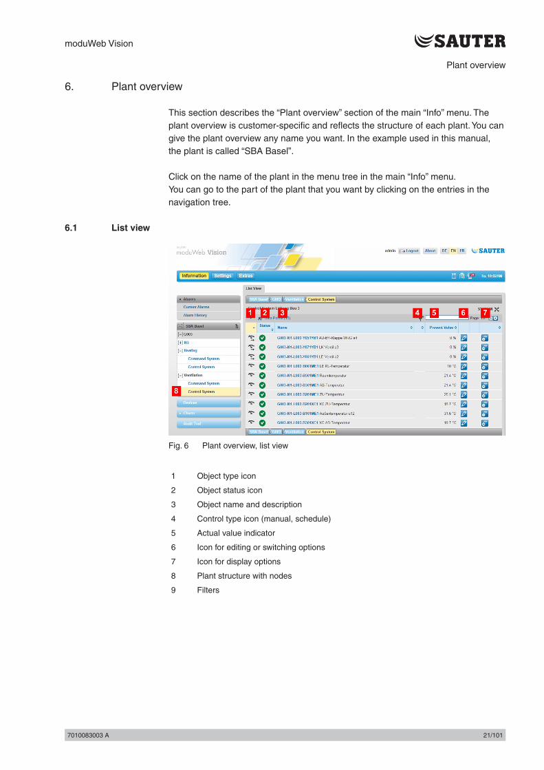
6.1 List view
Fig. 6 Plant overview, list view
1 Object type icon
2 Object status icon
3 Object name and description
4 Control type icon (manual, schedule)
5 Actual value indicator
6 Icon for editing or switching options
7 Icon for display options
8 Plant structure with nodes
9 Filters
moduWeb Vision
22/101 7010083003 A22/101 7010083003 A
Plant overview
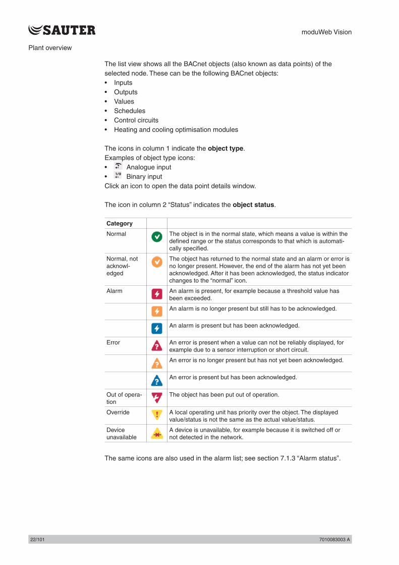
The list view shows all the BACnet objects (also known as data points) of the selected node. These can be the following BACnet objects:• Inputs• Outputs• Values• Schedules• Control circuits• Heating and cooling optimisation modules
The icons in column 1 indicate the object type.Examples of object type icons:• Analogue input• Binary inputClick an icon to open the data point details window.
The icon in column 2 “Status” indicates the object status.
Category
Normal The object is in the normal state, which means a value is within the defined range or the status corresponds to that which is automati-cally specified.
Normal, not acknowl-edged
The object has returned to the normal state and an alarm or error is no longer present. However, the end of the alarm has not yet been acknowledged. After it has been acknowledged, the status indicator changes to the “normal” icon.
Alarm An alarm is present, for example because a threshold value has been exceeded.
An alarm is no longer present but still has to be acknowledged.
An alarm is present but has been acknowledged.
Error An error is present when a value can not be reliably displayed, for example due to a sensor interruption or short circuit.
An error is no longer present but has not yet been acknowledged.
An error is present but has been acknowledged.
Out of opera-tion
The object has been put out of operation.
Override A local operating unit has priority over the object. The displayed value/status is not the same as the actual value/status.
Device unavailable
A device is unavailable, for example because it is switched off or not detected in the network.
The same icons are also used in the alarm list; see section 7.1.3 “Alarm status”.

moduWeb Vision
7010083003 A 23/1017010083003 A 23/101
Plant overview
Column 3 “Name” contains the name of the object. This corresponds to the “Description” property of the associated BACnet object. Click on the name to open the data point details window.
( Because “Description” is an optional property in the BACnet standards, the mandatory field “Object name” is used as an alternative. Normally, the BACnet object name is a specific abbreviation for the building which is understood by both the plant planners and operators.
The icons in column 4 indicate the control priority.( A prioritisation mechanism ensures that no conflicts occur between switchable
objects when they receive commands from different instances. For example, a pump may be automatically switched on and off by a schedule and is currently switched off. The user can then attempt to switch the pump on and thus override the automatic control. Conversely, a protection mechanism for the pump may in turn override the manual command from the user.
Column 5 "Present value" shows the current value of the BACnet object in engineering units.
In column 6, the icon indicates whether an object is writeable or switchable. If the data point is not writeable or switchable, the icon is greyed out.If the data point is writeable, you can click on the icon to open a window where you can change the value, for example a temperature setpoint. If the data point is switchable, you can click on the icon to open a window where you can carry out the switching operation, for example switching a pump on or off.
If, in addition to the icon, there is also a icon, which indicates that there is an active manual command or a manual entry by the user. Click this icon to return to automatic mode.
In column 7, icons such as or indicate that data logs or schedules are available for this object. Click one of these symbols to view this information.

moduWeb Vision
24/101 7010083003 A24/101 7010083003 A
Alarms

moduWeb Vision
7010083003 A 25/1017010083003 A 25/101
Alarms
7. Alarms
This section describes the “Alarms” area in the main “Info” menu.
Click “Alarms” in the menu tree in the main “Info” menu.
moduWeb Vision has two separate lists:• Current alarms All active alarms and errors in the system or inactive alarms and
errors that still have to be acknowledged.• Alarm history: Alarms and errors that are not active and do not have to be
acknowledged.
Both lists can be displayed in a "flat" view or a "grouped" view.
( Both alarm and error messages are listed. The term "alarm" is used for both in the following section.
The displayed messages not only include messages from BACnet (for example errors such as sensor interruptions, values outside the permissible range or failure to contact configured devices), but also internal system messages from moduWeb Vision (such as memory running out on the SD card, faulty configuration files and incorrectly configured server settings).
7.1 Definition of termsThe following section defines some important terms connected to alarm messages.
7.1.1 Alarm/error messagesA distinction is made between alarm messages and error messages.• An alarm message is triggered, for example, when a value is outside the set
maximum or minimum limit. This is a defined state and it can be assumed that the displayed valued are correct.
• An error message is triggered when the system enters an unexpected state, for example when there is a sensor interruption, a short circuit or a faulty configuration file. In this case, the displayed values for data points may be faulty.

moduWeb Vision
26/101 7010083003 A26/101 7010083003 A
Alarms
7.1.2 Alarm priorityThe priority (importance) of alarms is indicated by the following icons:
Risk of serious or fatal injury
Material damage
Monitoring
Problem
Miscellaneous, high priority
Miscellaneous, low priority
( These priorities are based on the defined message priority classification suggested in the BACnet standard.
7.1.3 Alarm statusThe current status of alarms is indicated by the following icons:
Category Status
Active Inactive, unacknowledged
Active, acknowledged
Alarm
Error
7.1.4 Changes of statusChanges of status are indicated by the following icons:
Category Change of status
From normal to abnormal,alarm or error active
From abnormal to normal, alarm or error inactive
Acknowledge-ment required
Acknowledged Acknowledge-ment required
Alarm
Error
The and icons only appear with alarms that require acknowledgement.

moduWeb Vision
7010083003 A 27/1017010083003 A 27/101
Alarms
7.1.5 AcknowledgementThe most recent change of status must be acknowledged if the settings for that require it. The reason for this is to make sure that a suitably authorised person notices the alarm and clicks the icon to indicate that they have seen it. This procedure ensures that alarm handling is reliable and traceable, and is also logged in the audit trail.
7.1.6 NotificationOptionally, selected user groups can be notified of alarms by e-mail and SMS. The alarm priorities are assigned to the various user profiles under “Notification settings” in the main “Settings” menu; see section 15.4 “Notification settings”.
7.1.7 TimestampEach alarm is given a timestamp. If the alarm is from the current day, the time of the alarm is displayed. If it is from another day, only the date is displayed. You can move your mouse over the timestamp to see a box with the date and time.
( The timestamp is generated by the automation station when the event occurs.
7.1.8 Alarm historyAll alarms that are no longer active are saved in the alarm history or moved there manually. A maximum of 500 alarms can be stored, after which the oldest entries are overwritten with the new ones.

moduWeb Vision
28/101 7010083003 A28/101 7010083003 A
Alarms
7.1.9 Grouped viewIn the grouped view, all changes of status of a BACnet object for an alarm group are shown together. This means the current status of an alarm can be seen in a line.In the grouped view, all changes of status of a BACnet object for an alarmClick “Current alarms” in the menu tree in the main “Info” menu.
Fig. 7 Alarm list, grouped view
1 Alarm priority icon
2 Time stamp
3 Alarm status icon
4 Description of the event
5 Object name and description
6 Icon for acknowledgement or intervention options
7 “Expand” icon
The icon in column 1 indicates the control priority.
Column 2 “Date” contains the timestamp for the last change of status for the alarm.
The icon in column 3 indicates the alarm status.
Column 4 “Date” contains the timestamp for the last change of status of the alarm.
Column 5 “Name /description” contains the source of the alarm.
In column 6, the icon indicates that a change of status must be acknowledged. If no acknowledgement is possible or required, the icon is greyed out.You can click on the icon to go to a window where you can carry out actions related to the alarm. If the option is not available, the symbol is greyed out.
You can expand any alarm to view all its changes of status by clicking on the “Expand” icon at the start of the line.

moduWeb Vision
7010083003 A 29/1017010083003 A 29/101
Alarms
Fig. 8 Alarm list, expanded grouped view
All changes of status and therefore the history of the alarm are displayed.
7.1.10 Flat viewThe flat view shows the same content as the grouped view. However, the individual changes of state are not grouped, but all shown in chronological order.
This gives you a better overview of the alarm occurrences over time. Because it is easier to see when each alarm was triggered, it is also easier to see how alarms from the various data points are related.
Fig. 9 Alarm list, flat view
moduWeb Vision
30/101 7010083003 A30/101 7010083003 A
Alarms
In the flat view, you can select several alarms and confirm them all together or move them to the alarm history.
Do do this, select the checkboxes at the beginning of the lines containing the alarms and carry out the required action using the icon.
( Instead of selecting them manually, you can use the icon and the options “All”, “All on page”, “None” or “None on page” to select or deselect all the alarms at once
( In certain circumstances there may be alarms in the active list that are no longer required or relevant (dead alarms). You can use this action to move them to the alarm history list, even though they do not meet the appropriate criteria. This may only be done with the utmost caution by authorised users and should not normally be necessary.

moduWeb Vision
7010083003 A 31/1017010083003 A 31/101
Devices
8. Devices
All devices and objects registered in moduWeb can be displayed in a list. You can view details on every device and object and also edit some of them.
8.1 Device and object listClick “Devices” in the menu tree in the main “Info” menu.
Fig. 10 Devices, device list
1 Device type icon
2 Device status icon
3 Object name and description
4 Device ID (BACnet DOI)
5 Icon for switching to the object list
A list of the registered devices is displayed.
The icon in column 1 represents the type of device. Click on the icon to go to the object list for this device.
( For Sauter devices, the icon resembles the device. For non-Sauter devices or devices whose type information is faulty or cannot be read for any other reason, the icon is a question mark.If you click an icon, a list view appears with all the objects in that device.
The icon in column 2 shows the current status of the device; see section 6 “Plant overview”.
Column 3 “Name” contains the name of the device. This corresponds to the “Description” property of the associated BACnet object.
( Because “Description” is an optional property in the BACnet standards, the mandatory field “Object name” is also used. Normally, the BACnet object name is a specific abbreviation for the building which is understood by both the plant planners and operators.
Column 4 “Device ID” shows the identification of the device.
You can use the icon in column 5 to switch to the object view of the device.

moduWeb Vision
32/101 7010083003 A32/101 7010083003 A
Devices
Click on the “Object list” tab.
Fig. 11 Device, object list
A list of all the registered objects is displayed.
The structure of the list basically corresponds to the description in section 6 “Plant overview”.
8.2 Device detailsClick an object name in the device list (see Fig. 10).
Fig. 12 Devices, standard view
The standard view shows all BACnet device objects.The icon indicates that an entry can be changed.
Click on the “Expert view” tab to open a window containing details.
8.3 Object detailsClick on the name of an object in the list (see Fig. 11).

moduWeb Vision
7010083003 A 33/1017010083003 A 33/101
Devices
Fig. 13 Objects, standard view
The most important details of an object are displayed in the standard view.The icon indicates that an entry can be changed. If an entry cannot be changed, the icon is greyed out.
Click on the “Expert view” tab to open a window containing all the details.

moduWeb Vision
34/101 7010083003 A34/101 7010083003 A
Charts

moduWeb Vision
7010083003 A 35/1017010083003 A 35/101
Charts
9. Charts
Charts are the diagrams of data point logs. There is a distinction between the following: • Simple charts (“Simple charts / logs” menu) • Combined charts (“Combined charts” menu)
Simple charts graphically display a logged data point without the user having to make any other settings.
Combined charts can show up to four simple data points at the same time. You can also make additional settings for combined charts; see section 12 “Chart settings”.
The charts can be compressed to a different number of measuring points depending on the time resolution.
9.1 Combined chartsAn overview of all the combined charts in the system can be found here.
Click “Charts” and then “Combined charts” in the menu tree in the main “Info” menu.
Fig. 14 Combined charts, overview
Here you can find information on the recorded charts such as the diagram name and the data point logs it contains.
Click on "List" to switch to the settings view; see section 12 "Chart settings".

moduWeb Vision
36/101 7010083003 A36/101 7010083003 A
Charts
To open a chart, click its name.
Fig. 15 Combined charts, chart
The appearance of combined charts is basically the same as that of simple charts (see section 9.2 "Simple charts / logs“), except that they show several data points simultaneously. Each data point is shown in a different colour.
Above the chart there is a key listing the displayed data points and the colours used for them.
As well as showing multiple data points in a single chart, the data points can also be displayed in separate charts.
moduWeb Vision
7010083003 A 37/1017010083003 A 37/101
Charts
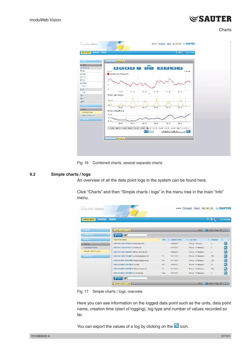
Fig. 16 Combined charts, several separate charts
9.2 Simple charts / logsAn overview of all the data point logs in the system can be found here.
Click “Charts” and then “Simple charts / logs” in the menu tree in the main “Info” menu.
Fig. 17 Simple charts / logs, overview
Here you can see information on the logged data point such as the units, data point name, creation time (start of logging), log type and number of values recorded so far.
You can export the values of a log by clicking on the icon.

moduWeb Vision
38/101 7010083003 A38/101 7010083003 A
Charts
Click on "List" to switch to the settings view; see section 12 "Chart settings".
Click on the name of a data point to open the corresponding chart.
Fig. 18 Simple charts / logs, chart
1 View selector icons
2 Data point name
3 Chart
4 Timeline
5 Timeline zoom icon
6 Export icon

moduWeb Vision
7010083003 A 39/1017010083003 A 39/101
Charts
View selector iconsYou can select the zoom level of the chart using the icons at the top. Click one of the symbols to change the section displayed.
Switch to full screen.The icon appears when you click .
Quit full screen mode.
You can use the other icons to change the zoom level of the chart. Click one of the symbols to change the section displayed.
Use the icons for “1 hour”, “24 hours (1 day)”, “7 days (1 week)” or “30 days (1 month)” to zoom in and out around the middle point until the displayed time range is as you want it.
View all values in the log.
You can use the “zoom in” and “zoom out” icons toincrease and reduce the zoom level.
You can also zoom in and out using the icons for “last hour”, “last 24 hours”, “last 7 days” and “last 30 days”.
In the chart (3), you can use the timeline (4) to zoom in and out and change the displayed section. • You can use your mouse pointer to select an area of the chart to enlarge. To do
this, hold down the left mouse button and move the mouse to the left or right.• An area on the timeline is displayed in a lighter colour than the rest. This lighter
area corresponds to the part of the chart that will be displayed. You can change the area using the to the left and right of it.
• You can move the lighter, active part of the timeline with your mouse pointer, which changes the part of the chart to be displayed.
You can use the two icons (5) to change the zoom level of the timeline.• When you zoom in or out, the active section of the timeline is also changed. You
can use these two icons to keep this section to the size that you want.
If you move your mouse over the chart, the current date and the value for this point are displayed.
You can export the values of this log by clicking on the icon (6). You can select the period of time and the resolution in a pop-up window.

moduWeb Vision
40/101 7010083003 A40/101 7010083003 A
Audit trail
moduWeb Vision
7010083003 A 41/1017010083003 A 41/101
Audit trail
10. Audit trail
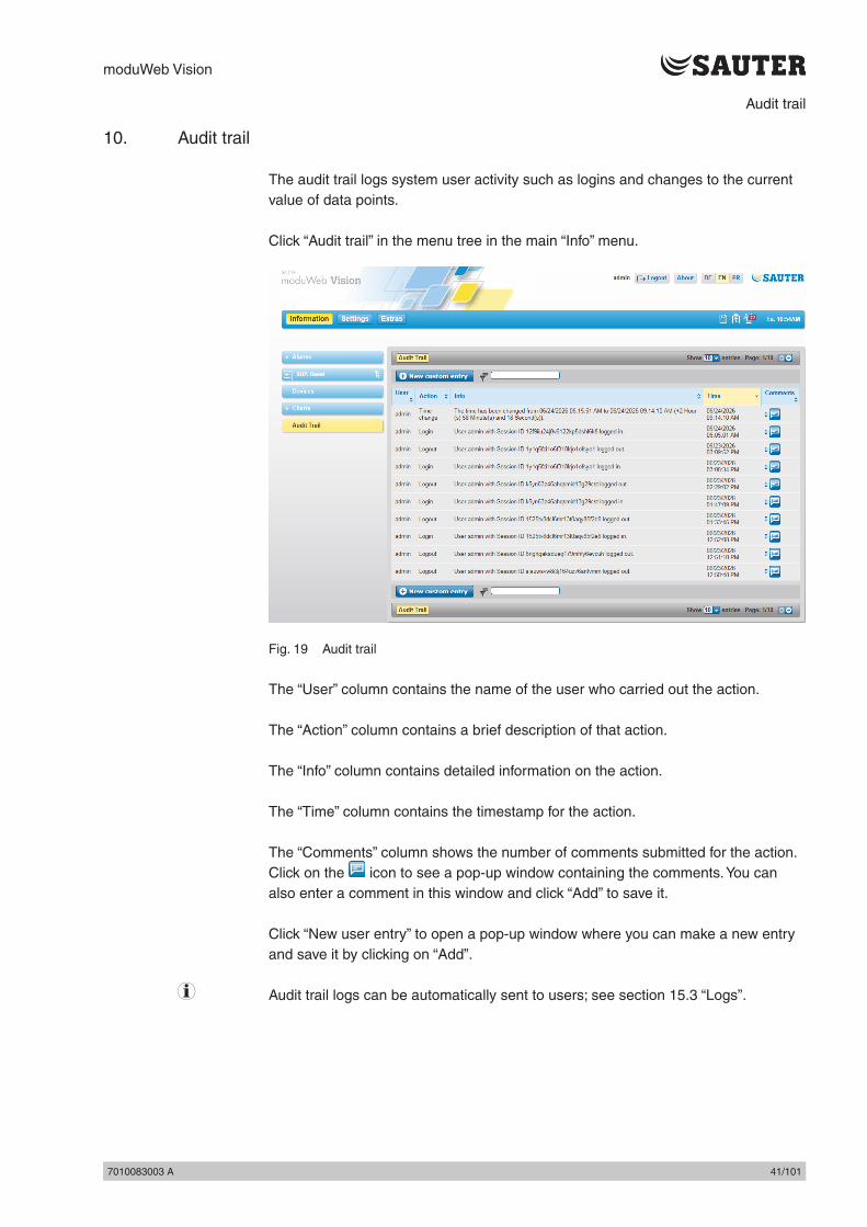
The audit trail logs system user activity such as logins and changes to the current value of data points.
Click “Audit trail” in the menu tree in the main “Info” menu.
Fig. 19 Audit trail
The “User” column contains the name of the user who carried out the action.
The “Action” column contains a brief description of that action.
The “Info” column contains detailed information on the action.
The “Time” column contains the timestamp for the action.
The “Comments” column shows the number of comments submitted for the action. Click on the icon to see a pop-up window containing the comments. You can also enter a comment in this window and click “Add” to save it.
Click “New user entry” to open a pop-up window where you can make a new entry and save it by clicking on “Add”.
( Audit trail logs can be automatically sent to users; see section 15.3 “Logs”.

moduWeb Vision
42/101 7010083003 A42/101 7010083003 A
Scheduling
moduWeb Vision
7010083003 A 43/1017010083003 A 43/101
Scheduling
11. Scheduling
In this menu you can view and edit all the schedules stored on the BACnet devices registered in moduWeb Vision.
11.1 SchedulesThe switching points for each day are defined in schedules. The switching points on normal days from Monday to Sunday are defined in the weekly schedule, while the switching points for non-standard periods are defined in the exception schedule.
Schedules can be applied to multiple data points of the same type. Data points can be added to or removed from a schedule.
Data from one schedule can be imported to another of the same type.
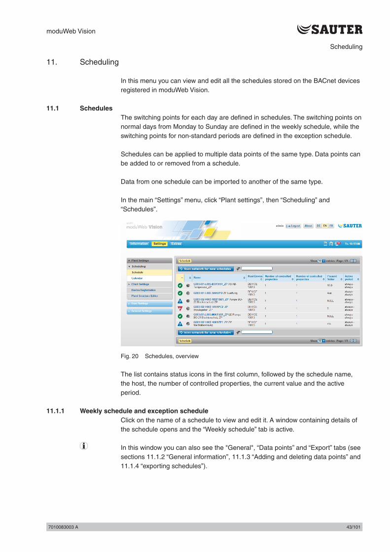
In the main “Settings” menu, click “Plant settings”, then “Scheduling” and “Schedules”.
Fig. 20 Schedules, overview
The list contains status icons in the first column, followed by the schedule name, the host, the number of controlled properties, the current value and the active period.
11.1.1 Weekly schedule and exception scheduleClick on the name of a schedule to view and edit it. A window containing details of the schedule opens and the “Weekly schedule” tab is active.
( In this window you can also see the "General", “Data points” and “Export” tabs (see sections 11.1.2 “General information”, 11.1.3 “Adding and deleting data points” and 11.1.4 “exporting schedules”).

moduWeb Vision
44/101 7010083003 A44/101 7010083003 A
Scheduling
Fig. 21 Schedules, weekly schedule
The information area consists of three sections:• The “Weekly schedule“ section in the top left is for defining switching points for
every day of the week.• The “Exception schedule“ section in the top right is for defining switching points
for exception periods.• The “Exception schedule entries” section at the bottom is for creating exception
periods.
Switching points already defined in the weekly and exception schedules are displayed.
( A default value specified in the BACnet device object is sent every day at midnight (00:00 hours). This switching point cannot be deleted.
moduWeb Vision
7010083003 A 45/1017010083003 A 45/101
Scheduling
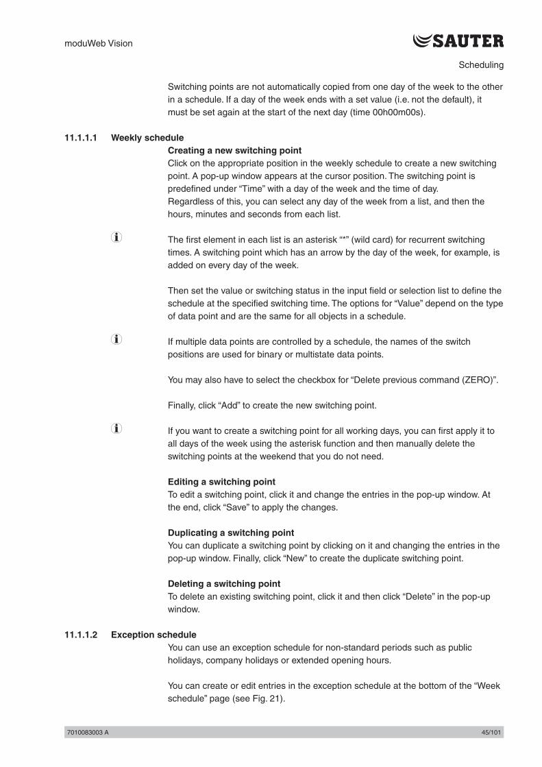
Switching points are not automatically copied from one day of the week to the other in a schedule. If a day of the week ends with a set value (i.e. not the default), it must be set again at the start of the next day (time 00h00m00s).
11.1.1.1 Weekly scheduleCreating a new switching pointClick on the appropriate position in the weekly schedule to create a new switching point. A pop-up window appears at the cursor position. The switching point is predefined under “Time” with a day of the week and the time of day. Regardless of this, you can select any day of the week from a list, and then the hours, minutes and seconds from each list.
( The first element in each list is an asterisk “*” (wild card) for recurrent switching times. A switching point which has an arrow by the day of the week, for example, is added on every day of the week.
Then set the value or switching status in the input field or selection list to define the schedule at the specified switching time. The options for “Value” depend on the type of data point and are the same for all objects in a schedule.
( If multiple data points are controlled by a schedule, the names of the switch positions are used for binary or multistate data points.
You may also have to select the checkbox for “Delete previous command (ZERO)”.
Finally, click “Add” to create the new switching point.
( If you want to create a switching point for all working days, you can first apply it to all days of the week using the asterisk function and then manually delete the switching points at the weekend that you do not need.
Editing a switching pointTo edit a switching point, click it and change the entries in the pop-up window. At the end, click “Save” to apply the changes.
Duplicating a switching pointYou can duplicate a switching point by clicking on it and changing the entries in the pop-up window. Finally, click “New” to create the duplicate switching point.
Deleting a switching pointTo delete an existing switching point, click it and then click “Delete” in the pop-up window.
11.1.1.2 Exception scheduleYou can use an exception schedule for non-standard periods such as public holidays, company holidays or extended opening hours.
You can create or edit entries in the exception schedule at the bottom of the “Week schedule” page (see Fig. 21).

moduWeb Vision
46/101 7010083003 A46/101 7010083003 A
Scheduling
( Only the individual exception periods, rather than switching times and values, are defined here. This is done afterwards on the right side of the window in the same way as for the weekly schedule.
To create a new exception period, go to “Exception schedule entries” and click “New”.
A pop-up window appears, in which you first have to select the priority.
( The priority is based on the priority property of the schedule object in BACnet. This property is defined and described in the BACnet standard. There are 16 priority levels, of which 1 is the highest. Some priority levels are reserved for certain functionalities in the BACnet standard and may not be used. The automation station is regulated with priority 16. Priority 8 is intended for manual operation (for example moduWeb or the modu840). A schedule can be set to the same priority level or a lower one (for example write priority 9).
Next, select the type of exception period from the list. The following are available:• Date (exception period for one particular day)• Period (exception for a period of time)• Day of the week (regularly recurring exceptions)• Calendar reference (exception based on a special calender, see section 11.2
“Calendar”)
Depending on the selected type, you must now set the repetition cycle, the time definition and the period of validity.
Finally, click “Save”.
You can then define the switching times and values in the right part of the “Exception schedule” window.

moduWeb Vision
7010083003 A 47/1017010083003 A 47/101
Scheduling
11.1.2 General informationClick on the “General” tab.
Fig. 22 Schedules, general
General information on the current schedule is shown here.
Values marked with the icon can be edited.
11.1.3 Adding and deleting data pointsSchedules can be applied to multiple data points at the same time. The data points to be controlled by a schedule must all be of the same type. You can add data points or remove them from a schedule in this window.
Click on the “Data points” tab.
moduWeb Vision
48/101 7010083003 A48/101 7010083003 A
Scheduling
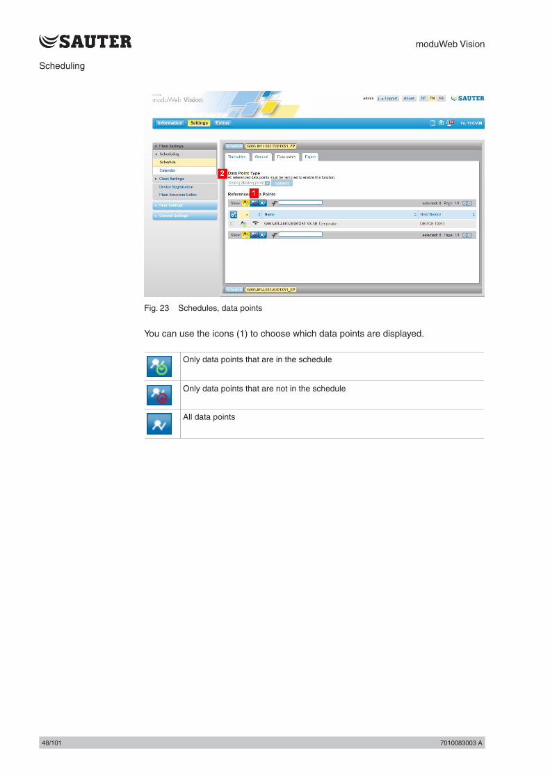
Fig. 23 Schedules, data points
You can use the icons (1) to choose which data points are displayed.
Only data points that are in the schedule
Only data points that are not in the schedule
All data points

moduWeb Vision
7010083003 A 49/1017010083003 A 49/101
Scheduling
Data point typeYou can select the data point type using the drop-down menu (2). Because a schedule can only contain data points of the same type, the choice is not offered if the schedule already contains a data point. If you want to change the type of data point, you must first delete the data points that are already in the schedule.
Select the checkboxes at the beginning of the lines containing the data points.
( Instead of selecting them manually, you can use the icon and the options “All”, “All on page”, “None” or “None on page” to select or deselect all the data points at once
Use the icon to select “Add to schedule” or “Delete from schedule”.
11.1.4 Exporting schedulesData from one schedule can be imported to another of the same type. You can also choose which properties are exported.
Click on the “Export” tab.
Fig. 24 Schedules, export
The list shows the schedules to which data from the current schedule can be exported. The data that is already in them will be overwritten.
Select the checkboxes at the beginning of the lines containing the data points.
( Instead of selecting them manually, you can use the icon and the options “All”, “All on page”, “None” or “None on page” to select or deselect all the schedules at once

moduWeb Vision
50/101 7010083003 A50/101 7010083003 A
Scheduling
Use the icon to select "Export".You can select the properties to be exported in the pop-up window that then appears. The following options are available:• Weekly schedule page• Exception schedule (without calendar references)• Active period • Default value for schedule • Write priority
Select the properties that you want and click “Export” to export them.
11.2 CalendarSimilar exception periods such as public holidays, company holidays and extended opening hours are defined in a calendar. The calendar can then be used as a reference for an exception period in an exception schedule.
In the main “Settings” menu, click “Plant settings”, then “Scheduling” and “Calendar”.
Fig. 25 Calendar, overview
The list contains status icons in the first column, followed by the name of the calendar, the host and the number of calendar entries.
11.2.1 Calendar viewClick on the name of a calendar to view and edit it. A window containing details of the calendar opens and the “Calendar” tab is active.
In this window you can also see the “Agenda view” and “Export” tabs (see sections 11.2.2 “Agenda view” and 11.2.3 “Exporting calendar entries”).
moduWeb Vision
7010083003 A 51/1017010083003 A 51/101
Scheduling
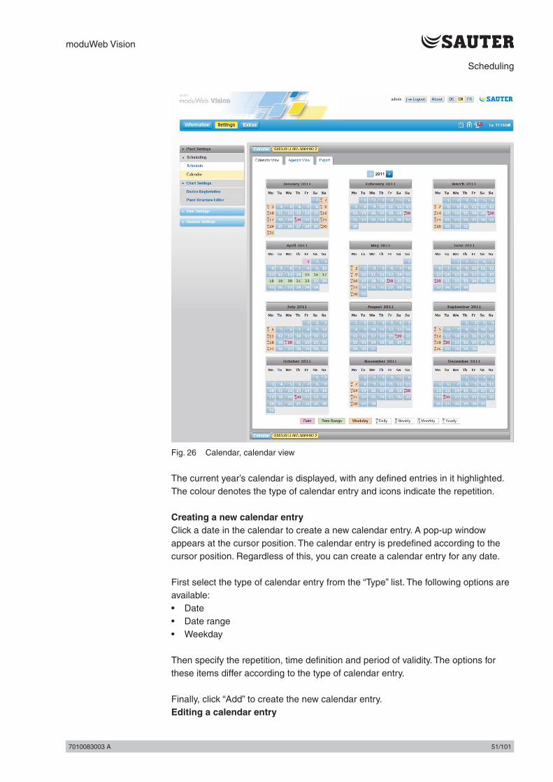
Fig. 26 Calendar, calendar view
The current year’s calendar is displayed, with any defined entries in it highlighted. The colour denotes the type of calendar entry and icons indicate the repetition.
Creating a new calendar entryClick a date in the calendar to create a new calendar entry. A pop-up window appears at the cursor position. The calendar entry is predefined according to the cursor position. Regardless of this, you can create a calendar entry for any date.
First select the type of calendar entry from the “Type” list. The following options are available:• Date• Date range• Weekday
Then specify the repetition, time definition and period of validity. The options for these items differ according to the type of calendar entry.
Finally, click “Add” to create the new calendar entry.Editing a calendar entry

moduWeb Vision
52/101 7010083003 A52/101 7010083003 A
Scheduling
To edit a calendar entry, click it and change the specifications in the pop-up window. At the end, click “Save” to apply the changes.
Deleting a calendar entryTo delete an existing calendar entry, click it and then click “Delete” in the pop-up window.
( You can also edit or delete calendar entries in the “Agenda view” tab as described below.
11.2.2 Agenda viewClick on the “Agenda view” tab.
Fig. 27 Calendar, agenda view
The entries in the calendar are shown in an agenda view here.
You can edit the entries after clicking on the icon.
Click on the icon to delete entries from the calendar.
11.2.3 Exporting calendar entriesCalendar entries can be exported to other calendars in the system. You can also choose which entries are exported.
Click on the “Export” tab.

moduWeb Vision
7010083003 A 53/1017010083003 A 53/101
Scheduling
Fig. 28 Calendar, export
The list shows the calendars to which entries from the current calendar can be exported. The entries that are already in them will be overwritten.
Select the checkboxes at the beginning of the lines containing the required calendars.
( Instead of selecting them manually, you can use the icon and the options “All”, “All on page”, “None” or “None on page” to select or deselect all the calendars at once
Use the icon to select "Export".
You can select the entries to be exported in the pop-up window that then appears.
Select the entries that you want and click “Export” to export them.

moduWeb Vision
54/101 7010083003 A54/101 7010083003 A
Chart settings

moduWeb Vision
7010083003 A 55/1017010083003 A 55/101
Chart settings
12. Chart settings
The "Chart settings" menu is where you configure the data point logs that are displayed under “Charts” in the main “Info” menu (see section 9 “Charts”).
There is a distinction between the following: • Simple charts (“Simple charts / Logs” menu) • Combined charts (“Combined charts” menu)
Simple charts graphically display a logged data point without the user having to make any other settings.
Combined charts can show up to four simple data points in a single diagram at the same time. This makes the charts clearer to read and easier to compare.
( If no SD card is installed, no data points will be recorded and no log data will be available to be displayed in the charts.
12.1 Simple charts / LogsIn the main “Settings” menu, click “Plant settings”, then “Chart settings” and “Simple charts / Logs”.
Fig. 29 Simple charts / Logs, overview
An overview of all the data point logs in the system is displayed here. Logs with faulty log configurations are also displayed, as are those whose data point is no longer in the system.
Information on the logged data point is displayed, such as the current status, data point name, creation time (start of logging), stop time (for logs that are no longer recorded), log type and memory utilisation. You can carry out various actions with the icons in the last column.

moduWeb Vision
56/101 7010083003 A56/101 7010083003 A
Chart settings
The icons in the first column “Status” are explained in section 6.1 “List view”. Click on "List" or the icon to switch to the chart view; see section 9 "Charts".
( To the upper right of the list you can see information such as the total memory required by the logs and how much memory is available on the SD card.
Creating a new chart / data point logClick “New”. The “Logging type” window appears.
In this window you must choose a logging type from the list:• Polling – the station is queried at regular intervals (“Refresh rate”) whether it has
a new value for this data point • COV (change of values) – a value is logged when it changesIf you select polling, you must also specify the refresh rate.
Then click “Next”. The “Select data points” window appears.
A list of all the data points in the system appears. You must select the required data points. To do this, select the checkboxes at the start of the line.
( Instead of selecting them manually, you can use the icon and the options “All”, “All on page”, “None” or “None on page” to select or deselect all the data points at once.
Then click “Next”. A summary of all the settings that have been made appears.
Click “Save” to create a new chart or log for each of the selected data points.
Change data pointYou can use this action to change the data point. Click on the icon in the appropriate line and select “Change data point”. Select the new data point in the window that appears and then clock “Save” to execute the action.
( When you change the data point, the logs of the previous data point are not deleted, but instead continued with information from the new data point. You might need to do this, for example, when you want to continue logging a data point although it has been moved from one device to another.
( You can also add a new data point to the system. To do this, go to the “Device registration” or “Plant structure editor” menu (see sections 13 “Device registration” and 14 “Plant structure editor”.
Change logging typeYou can use this action to change the logging type. Click on the icon in the appropriate line and select “Change logging type”. Select the new logging type and refresh rate in the pop-up window and click “Save” to execute the action.
Reset log

moduWeb Vision
7010083003 A 57/1017010083003 A 57/101
Chart settings
This action permanently deletes the previous log of the data point. However, the log configuration is not lost, and it recommences immediately. Click on the icon in the appropriate line and select “Change logging type”. The action is executed after you answer a security query.
Delete simple chart / data point logThis action deletes the log of the data point as well as the log configuration. Click on the icon in the appropriate line and select “Delete”. The action is executed after you answer a security query.
Pause/resume actionYou can pause the logging of a data point by clicking on the icon in the appropriate line. The symbol changes to . Click on the icon to resume the logging.
CSV exportThe action exports the values of the log. Click on the icon in the appropriate line and select “CSV export”. You can select the period of time and the resolution in a pop-up window.
Create new configuration for data point logIf there is no digram configuration for a data point, you can create a new one by clicking on the icon. A pop-up window appears, in which you can select the new logging type and refresh rate. Click “Create” to execute the action.
12.2 Combined chartsIn the main “Settings” menu, click on “Plant settings”, then “Chart settings” and “Combined charts”.
Fig. 30 Combined charts, overview
An overview of all the combined charts in the system can be found here. You can find information on the recorded charts such as the diagram name and the data point logs it contains.You can carry out various actions with the icons in the last column.
Click on "List" or the icon to switch to the chart view; see section 9 "Charts".
moduWeb Vision
58/101 7010083003 A58/101 7010083003 A
Chart settings
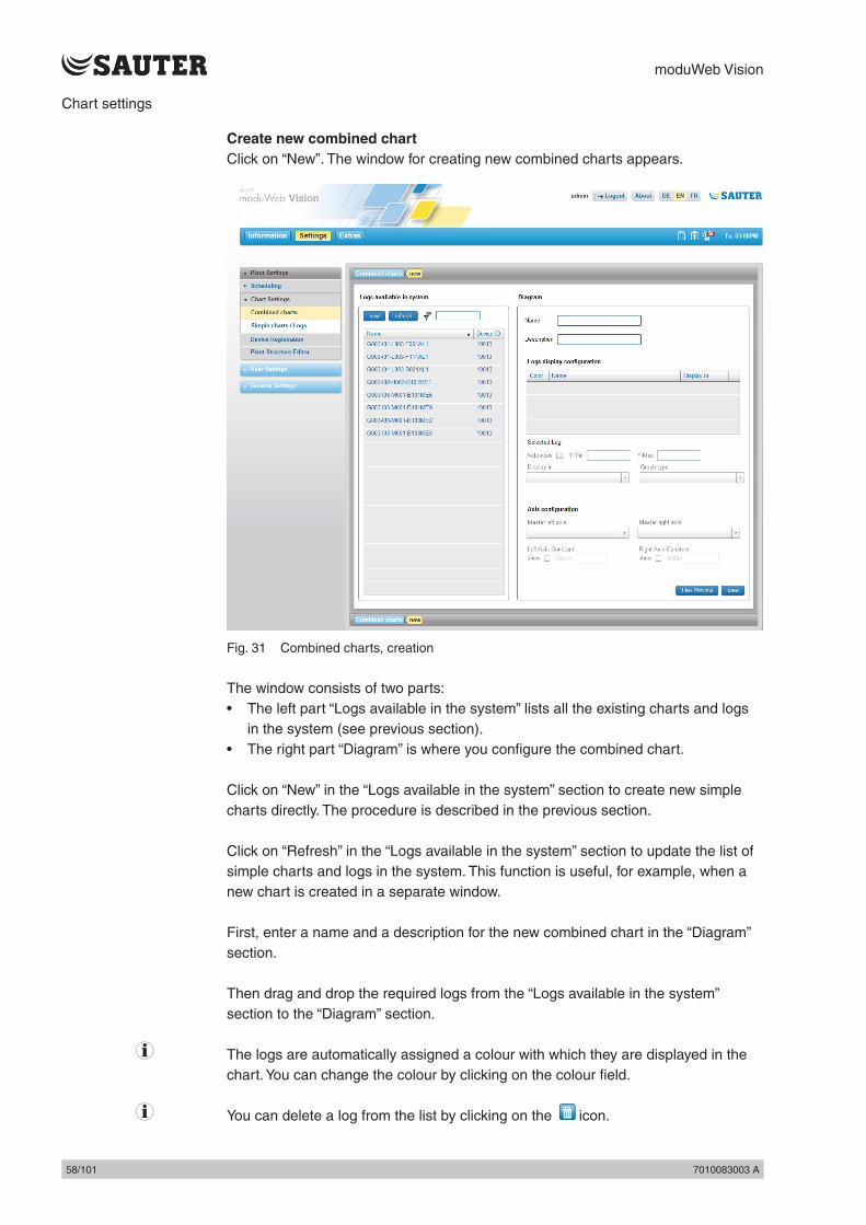
Create new combined chartClick on “New”. The window for creating new combined charts appears.
Fig. 31 Combined charts, creation
The window consists of two parts:• The left part “Logs available in the system” lists all the existing charts and logs
in the system (see previous section).• The right part “Diagram” is where you configure the combined chart.
Click on “New” in the “Logs available in the system” section to create new simple charts directly. The procedure is described in the previous section.
Click on “Refresh” in the “Logs available in the system” section to update the list of simple charts and logs in the system. This function is useful, for example, when a new chart is created in a separate window.
First, enter a name and a description for the new combined chart in the “Diagram” section.
Then drag and drop the required logs from the “Logs available in the system” section to the “Diagram” section.
( The logs are automatically assigned a colour with which they are displayed in the chart. You can change the colour by clicking on the colour field.
( You can delete a log from the list by clicking on the icon.

moduWeb Vision
7010083003 A 59/1017010083003 A 59/101
Chart settings
Every log in the list can be given the following attributes. The attributes are assigned to the highlighted data point, which is also shown in “Selected log”.• If “Autoscale” is enabled, the value range of the Y-axis is automatically
determined according to the currently visible area. • “Y-Min” and “Y-Max” are disabled.• You can set the Y-axis range manually using “Y-Min” and “Y-Max”. “Y-Min” and
“Y-Max” are only enabled when “Autoscale” is disabled. ( If this range is set too high, for example, the log will simply appear as a straight
line. If the value of “Y-Max” is less than the minimum value, the log will not appear at all.
• “Display in” allows you to choose where the log will be displayed in the chart. The following options are available:
• With “Main diagram left” the log is shown on the left Y-axis of the main diagram.
• With “Main diagram right axis” the log is shown on the right Y-axis of the main diagram.
• With “Separate diagram”, the log is shown in a separate diagram below the main diagram.
• “Graph type” allows you to choose whether the individual values of the log are connected in a direct line or in steps.
( By default, analogue data points are shown as lines, while binary and multistate data points are shown as steps.
Under “Axis configuration” you can choose which logs are used as “masters” for the right and left axis of the chart. If a master has been set for an axis, its value range is used as a reference for all others on the axis. If a combined chart only contains one log, this is automatically set to the left axis.
You can click on “Live preview” to see the resulting combined chart with this configuration.
Click on “Save” to create the new combined chart.
Edit combined chartClick on the icon to edit a combined chart. The same window appears as when you create a new chart, but the settings of the configuration to be edited are already loaded. Make the changes and click on “Save” to apply them.
Duplicate combined chartThis function allows you to use existing combined charts as templates for new ones without having to make the settings again. Click on the icon in the appropriate line.
Delete combined chartThis action deletes a combined chart. Click on the icon in the appropriate line.
( When you delete a combined chart, the simple charts and log data displayed in it are not deleted.

moduWeb Vision
60/101 7010083003 A60/101 7010083003 A
Chart settings

moduWeb Vision
7010083003 A 61/1017010083003 A 61/101
Device registration
13. Device registration
All devices that you want to display and operate in moduWeb Vision must be registered. Only registered devices are monitored and have alarms, for example, displayed for them.
Devices are usually registered when the plant is commissioned by SAUTER specialists. The loading process can take a few minutes. The function described below can be used to register additional devices or delete devices for moduWeb Vision when the system is already in operation.
Improper changes to the device registration can result in parts of the plant no longer being properly monitored or being incapable of operation.
In the main “Settings” menu, click “Plant settings”, then “Plant settings” and “Device registration”.
Fig. 32 Device registration
The content area is divided into two sections. • The left side shows all devices that have been found in the network and
communicate via the BACnet/IP protocol. • The right side shows the stations that are registered in moduWeb Vision.
The lists show the device type, the device name, a description and the unique DOI (device object identifier) in the network.

moduWeb Vision
62/101 7010083003 A62/101 7010083003 A
Device registration
( The device type is indicated by an icon. For Sauter devices, the icon resembles the device. For non-Sauter devices or devices whose type information is faulty or cannot be read for any other reason, the icon is a question mark.
To register a device, drag and drop it from the list on the left to the one on the right.
To delete a registered device, click on the icon. It is deleted from the listed of registered devices and moved to the list on the left.
( When this window is loaded, the system automatically scans the network for BACnet devices and the detected devices are displayed. You can also start the scan manually by clicking on the icon.
Finally, click on “Save”.

moduWeb Vision
7010083003 A 63/1017010083003 A 63/101
Plant structure editor
14. Plant structure editor
This function is for administering the moduWeb Vision visualisation structure. Various objects can be integrated in a structural configuration and thus visualised. This visualisation appears as a “navigation tree” in the menu tree.
The visualisation structure is usually set up when SAUTER specialists put the system into service. The function described below can be used for editing the visualisation structure when the system is in operation.
In the main “Settings” menu, click on “Plant settings”, then “Plant settings” and “Plant structure editor”.
Fig. 33 Plant structure editor, device overview
The content area is divided into two sections. • The left side lists the objects in moduWeb Vision that can be included in the
visualisation structure. Various types of object can be included and are described in more detail below.
• The right side contains the moduWeb Vision visualisation structure. The structure is tree-shaped (like the folder structure of a computer) and can be edited; see section 14.2 “Visualisation structure”.

moduWeb Vision
64/101 7010083003 A64/101 7010083003 A
Plant structure editor
14.1 Object typesThe term “objects” not only refers to BACnet objects (such as analogue inputs and outputs) that are included in moduWeb Vision via a registered device, but also to non-BACnet objects. This means objects that do not come from the “BACnet world” but can still be structured and visualised with moduWeb Vision.
Click on the tab of the left part of the screen to switch between the various object types. The following object types are possible:
BACnet objects of registered devices
Uploaded documents
Charts of logs
Web links
BACnet objects
Fig. 34 Plant structure editor, BACnet objects
These are objects located on a device that is registered in moduWeb. If you click on a device, the BACnet objects located in this device are displayed. The current device names are shown above the list. Click on “Back” to return to the device overview.

moduWeb Vision
7010083003 A 65/1017010083003 A 65/101
Plant structure editor
The objects of a device are divided into three categories. Click on the tab of the left part of the screen to switch between the various object types. The following categories are possible:
Data pointsShows all data points (AI, AO, AV, BI, BO, BV, MI, MO, MV) of the selected device.
Schedules/calendar Shows all schedules and calendar objects of the selected device.
Special objects Shows all special objects (Loop, OptH?, OptC?) of the selected device.
Documents
Fig. 35 Plant structure editor, document object type
Useful documents such as plant descriptions, diagrams, data sheets and manuals can be assigned to a node.
These objects are linked to a document file. The objects consist of a name, a description and a file that users can store in moduWeb Vision to access. The document objects are displayed in the list.

moduWeb Vision
66/101 7010083003 A66/101 7010083003 A
Plant structure editor
Click on “New” to add new documents. Enter a name and a description in the pop-up window and select the file to upload. Finally, click on “Save”.
You can use the icon to edit the names and descriptions of existing documents.
Click on the icon to delete documents from the system.
Charts
Fig. 36 Plant structure editor, chart object type
These are objects which represent a combined chart.
Click on “New” to create new combined charts. A window for creating new combined charts appears; see section 12 “Chart settings”. Make the settings and then click on “Save”.
You can use the icon to edit an existing combined chart. Make the changes in the window that appears and then click on “Save”.
Click on the icon to delete combined charts from the system.
( Combined charts are normally created and edited in the “Chart settings” menu of the main “Settings” menu; see section 12 "Chart settings".
Web links

moduWeb Vision
7010083003 A 67/1017010083003 A 67/101
Plant structure editor
Fig. 37 Plant structure editor, web link object type
Useful links to websites such as webcams, service contacts, shift plans and weather information can be assigned to a node.
These objects contain a link to a site via an internet address (e.g. www.sauter.ch).
Click on “New” to add new documents. Enter a name, a description and an address in the pop-up window. Finally, click on “Save”.
Click on the icon to edit existing web links.
Click on the icon to delete web links from the system.

moduWeb Vision
68/101 7010083003 A68/101 7010083003 A
Plant structure editor
14.2 Visualisation structureThe right side of the content area (see Fig. 33) contains the visualisation structure. The structure has the form of a tree, like the folder structure of a computer.
The top node is mandatory. It can be edited and renamed, but not deleted. Other nodes can be added to this one.
( There is no limit to the number of hierarchical levels, and every node can be linked to any number of sub-nodes.
( The number in brackets beside the name of each node indicates how many objects (BACnet objects, document objects, chart objects, web link objects) there are in this node.
To the right of the column there are icons which you can use to configure the nodes.
( Changes to the structure are not applied until you click on “Save”. This means you can reverse any changes made by mistake by exiting the window without clicking on “Save”.
Adding nodesYou can add a new node to any node using the icon. The added node is given a default name. This consists of the name of the node it was added under, plus the current number of nodes in the structure. The name can be changed.
Deleting nodesTo delete a node, click on the icon and select “Delete” from the list of options that appears. The node is deleted, along with all the objects and configurations it contains.
Moving nodesYou can move a node elsewhere in the structure by cutting and pasting it. To do this, click on the icon of the node to be moved and select “Cut” from the list of options that appears. The node is removed and stored in a buffer. You can then add it to another node.To do this, click on the icon of the node you want to paste it into and then select “Paste” from the list of options. The node you cut out, along with all its settings and the objects it contains, is added below the selected node.
Copying nodesYou can copy a node and paste it anywhere in the structure.To do this, click on the icon of the node to be copied and select “Copy” from the list of options that appears. The node is stored in a buffer. You can then add it to another node.
To do this, click on the icon of the node you want to paste it into and then select “Paste” from the list of options.

moduWeb Vision
7010083003 A 69/1017010083003 A 69/101
Plant structure editor
The copied node, along with all its settings and the objects it contains, is added below the selected node.
Editing nodesEach node consists of a series of attributes (name, description) as well as the BACnet and non-BACnet objects it contains.
Click on the icon to open the properties window.
Fig. 38 Plant structure editor, BACnet objects
The “General” tab of the window shows the attributes of the node. You can edit these.
The various objects are listed on the other tabs.
Objects with a icon can be deleted.
( You must click “OK to confirm any changes before they are saved.

moduWeb Vision
70/101 7010083003 A70/101 7010083003 A
Settings

moduWeb Vision
7010083003 A 71/1017010083003 A 71/101
Settings
15. Settings
In the “Settings” menu you can make important settings for moduWeb vision functions.
The window consists of three parts:• Plant settings• These are described in sections 13 “Device registration” and 14 “Plant structure
editor”.• User settings• User administration and definition of alarm notifications to users via e-mail or
SMS• General settings• Basic settings for the system configuration, notification mechanisms, network
etc.• These general settings are usually the first to be made when the system is put
into operation.
Click on “Settings” in the main menu to open a screen with information on that menu.
Fig. 39 Settings, info screen
15.1 User management
15.1.1 Roles (user groups)moduWeb Vision distinguished the four following preconfigured roles (user groups):• Administrator• Specialist• User• Guest
The roles are assigned different rights to access the functions and information in moduWeb Vision. The availability of menus and the ability to edit parameters and values differ according to the role. The role is assigned by the administrator when the user is created.
The users themselves cannot change their roles or authorisations.

moduWeb Vision
72/101 7010083003 A72/101 7010083003 A
Settings
Users who are registered as administrators still have the option of individually allowing or prohibiting access to individual equipment systems and nodes when creating and editing users. Prohibited equipment systems and nodes are not visible to the user.
At least one user must be created as an administrator. If only one administrator has been created, it cannot be deleted. For security reasons, it is advisable to change the preset user name “admin” and default password “passwd”.
The following table shows an example of how individual authorisations can be assigned to roles:
Authorisation Guest User Specialist Administrator
Login / logout • • • •
Observe • • • •
Change setpoints • • •
The assignments are predefined in the system.
15.1.2 Creating a new userA user who is registered as an administrator can create new users.
Click on “User management” in the main “Settings” menu (this is only available if you are logged in as an administrator).
Fig. 40 User management, overview (only visible to “Admin” role)
A list of all the existing users appears.

moduWeb Vision
7010083003 A 73/1017010083003 A 73/101
Settings
Click on “New”. The input dialogue for user data appears.
Fig. 41 User management, input dialogue for user data
The fields in the input dialogue have the following functions:
User nameThe name of the user for authentication in the login screen. This item can only be changed by users with administrator rights when creating a new user.The user name must have at least 4 and no more than 16 characters. All alphanumerical characters and a number of special characters (! $ = / \ ? + - _ ( ) [ ] { } < > #) are allowed. The characters are visible in plain text. They are not case-sensitive.
PasswordThe password for logging into moduWeb Vision must have at least 6 and no more than 16 characters. It is used for authentication when logging in. Together with the user name, the access rights are specified by the administrator. All alphanumerical characters and a number of special characters (! $ = / \ ? + - _ ( ) [ ] { } < > #) are allowed for the password. The characters are not visible while they are being entered. They are case-sensitive. The password may not be the same as the user name.
Verify passwordThe password must be entered again here.
RoleThe predefined roles are available here (administrator, specialist, user, guest). This choice is only available to users with administrator rights.
NameThe full name of the user is entered here. This might be different from the name entered under “User”. The full name is a mandatory field.
E-mailThe address entered here is used for e-mail notifications to the user.

moduWeb Vision
74/101 7010083003 A74/101 7010083003 A
Settings
( In order for a notification to take place, the settings must be made as described in sections 15.2 “User notification” and 15.4 “User notification settings”.
Mobile phone (for SMS notification)The mobile phone number entered here is used to send SMS notifications to the user.In order to make an SMS notification, an e-mail must be sent to an appropriate internet SMS gateway, which then forwards the e-mail to the mobile number in the form of an SMS.
Alternative phoneAn alternative telephone number for contacting the user can be entered here.
The “User name”, “Password” and “Name” fields are mandatory. Then click on “Next”. The window for the visibility settings appears:
Fig. 42 User management, visibility settings

moduWeb Vision
7010083003 A 75/1017010083003 A 75/101
Settings
Here you can define which equipment systems and nodes are visible to the new user.
First highlight the equipment systems that the user should see in the “Visible systems” column on the left. The right column “Visible nodes” changes accordingly by disabling the visibility icons of nodes with equipment systems that are marked as invisible on the left.
Other nodes are also made invisible in the column on the right. This is because of the hierarchy of the tree structure: if a node is invisible, then so are all its sub-nodes.
Then click on “Next”. A summary of the settings made for the new user appears.
Fig. 43 User management, new user summary
Click on “Save”.
The entries are saved and the new user appears in the user management summary window.

moduWeb Vision
76/101 7010083003 A76/101 7010083003 A
Settings
15.1.3 Editing usersA user who is registered as an administrator can edit existing users.
Click on the user name in the user management summary window. The details of that user appear.
Fig. 44 User management, individual user data
( You can use the “Send test e-mail” and “Send test SMS” functions to send a test e-mail or SMS to the user’s e-mail address or mobile phone number.
Click on “Edit”. The input dialogue for user data appears.
( You can also view this window by clicking on the icon of the appropriate line in the user management summary window.
Fig. 45 User management, input dialogue for user data
This is the same as the input mask for creating a new user. You can change all the data except the user name. Click on “Save” to save the changes.

moduWeb Vision
7010083003 A 77/1017010083003 A 77/101
Settings
You can click on the visibility settings tab to go to the visibility settings window, where you can make and save changes.
15.1.4 Duplicating usersA user who is registered as an administrator can duplicate existing users.
To do this, click on the symbol in the corresponding line in the user management summary window.
The input dialogues that appear when you duplicate a user are the same as those that appear when you create a new user.All possible entries and settings are copied from the selected existing user, except for the user name and password. The copied entries can be changed.
The system suggests the previous user name, which you must change.
15.1.5 Deleting usersA user who is registered as an administrator can delete existing users.
To do this, click on the symbol in the corresponding line in the user management summary window.
After a security query, the user is deleted.
15.1.6 Changing your own details/passwordInstead of the “User management” menu, users who are not registered as administrators (specialists, users or guests) see the “My profile” menu, where they can view their own details.
Most of the user data and the password can be changed by clicking on “Edit”. The user name, the role and the visibility settings cannot be changed.
( You can use the “Send test e-mail” and “Send test SMS” functions to send a test e-mail or SMS to the user’s e-mail address or mobile phone number.
15.2 User notificationmoduWeb Vision can notify users of alarms that occur. You can choose the conditions and method (e-mail or SMS) for notifying a user of alarms.
( SMS notifications are sent by e-mail via an SMS gateway. The SMS gateway forwards the content of the e-mail in the form of an SMS to the user’s mobile phone number that was entered in the user management.

moduWeb Vision
78/101 7010083003 A78/101 7010083003 A
Settings
To configure alarm notifications, you must first make settings in the “General settings, notification settings” menu of the main “Settings” menu; see section 15.4 “Notification settings”:• Configure the mail server• Define notification profiles, recipient groups and the type of alarms that are
reported to them• Define the standard e-mail format and content• Define the standard SMS format and content
( The process for converting e-mails to SMS via an SMS gateway may differ, depending on the telecommunications provider. You may need to contact the provider.
After this, you can make the settings for specific users described below. The condition is that the users have already been created and the plant has been defined.• Alarm notification,
assignment of notification profile to a user• E-mail format,
optional setting when the standard e-mail format cannot be used for the user• SMS format,
optional setting when the standard SMS format cannot be used for the user• System logs
The condition for the settings described below is that the notification settings have been made in accordance with section 15.4 “Notification settings”.
15.2.1 Alarm notificationAdministrators can configure notification for themselves and other users here.Users who are not administrators (specialists, users or guests) can only view and edit their own settings.
In the main “Settings” menu, click on “User settings”, then “User notification”, “Alarming” and “Alarm notification”.
( Non-administrators must go to the main “Settings” menu and then click on “User settings”. “My notifications”, “Alarming” and “Alarm notification”.

moduWeb Vision
7010083003 A 79/1017010083003 A 79/101
Settings
Fig. 46 Alarm notification
The notification profiles defined in the general settings under “Notification profiles” are displayed.
For “Active user”, select the user whose alarm notification you want to configure (this is only possible for users registered as administrators).
Highlight “E-mail” or “SMS” below each profile to define whether the selected active user is notified of alarms in the profile vie e-mail or SMS.
( The individual data, e-mail address and mobile phone number shown in the lower section are for information only. They can be changed in the user management.
Finally, click on “Save”.
15.2.2 E-mail formatAdministrators can configure the content of alarm e-mails for any user here. Users who are not administrators (specialists, users or guests) can only view and edit their own settings.
In the main “Settings” menu, click on “User settings”, then “User notification”, “Alarming” and “E-mail format”.
( Non-administrators must go to the main “Settings” menu and then click “User settings”. “My notifications”, “Alarming” and “E-mail format”.

moduWeb Vision
80/101 7010083003 A80/101 7010083003 A
Settings
Fig. 47 E-mail format
For “Active user”, select the user who these settings will apply to (this is only possible for users registered as administrators).
Use the two buttons below to make the following basic setting:
“Use default message format” means that no further configuration is possible and the template configured in “Default e-mail format” is used. In this case, the other fields in the window cannot be edited.
“Use user-specific message format” means that a specific configuration in the message structure is used. In this case, the other fields in the window can be edited.• For “E-mail language”, select the language in which the placeholder variables
are displayed. • For “E-mail subject, enter the text for subject line and for “E-mail content”, enter
the content. You do this using a combination text that you enter and placeholders (the blue terms below "Placeholder variables”). The placeholders stand for the various dynamic parameters of an alarm, for example, and are replaced with the actual content of the variable when the e-mail is sent. You can add placeholders to the subject or content by clicking on the blue parameter text at the current cursor position.
Click on “Preview” to see an example of the configuration.
Finally, click on “Save”.

moduWeb Vision
7010083003 A 81/1017010083003 A 81/101
Settings
15.2.3 SMS formatAdministrators can configure the content of SMS alarm notifications for any user here.Users who are not administrators (specialists, users or guests) can only view and edit their own settings.
In the main “Settings” menu, click on “User settings”, then “User notification”, “Alarming” and “SMS format”.
( Non-administrators must go to the main “Settings” menu and then click on “User settings”. “My notifications”, “Alarming” and “SMS format”.
Fig. 48 SMS format
For “Active user”, select the user who these settings will apply to (this is only possible for users registered as administrators).
Use the two buttons below to make the following basic setting:
“Use default message format” means that no further configuration is possible and the template configured in “Default SMS format” is used. In this case, the other fields in the window cannot be edited.
“Use user-specific message format” means that a specific configuration in the message structure is used. In this case, the other fields in the window can be edited.• For “Language”, select the language in which the placeholder variable are
displayed. • For “Subject, enter the text for subject line and for “Content”, enter the content.
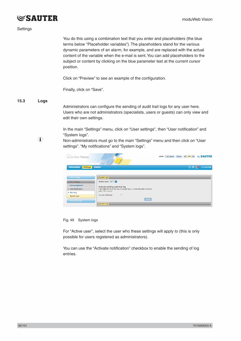
moduWeb Vision
82/101 7010083003 A82/101 7010083003 A
Settings
You do this using a combination text that you enter and placeholders (the blue terms below "Placeholder variables”). The placeholders stand for the various dynamic parameters of an alarm, for example, and are replaced with the actual content of the variable when the e-mail is sent. You can add placeholders to the subject or content by clicking on the blue parameter text at the current cursor position.
Click on “Preview” to see an example of the configuration.
Finally, click on “Save”.
15.3 LogsAdministrators can configure the sending of audit trail logs for any user here.Users who are not administrators (specialists, users or guests) can only view and edit their own settings.
In the main “Settings” menu, click on “User settings”, then “User notification” and “System logs”.
( Non-administrators must go to the main “Settings” menu and then click on “User settings”. “My notifications” and “System logs”.
Fig. 49 System logs
For “Active user”, select the user who these settings will apply to (this is only possible for users registered as administrators).
You can use the “Activate notification” checkbox to enable the sending of log entries.
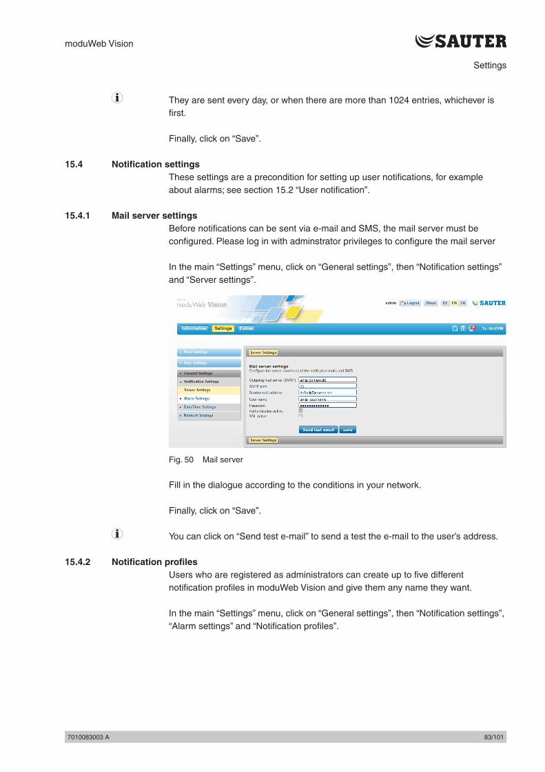
moduWeb Vision
7010083003 A 83/1017010083003 A 83/101
Settings
( They are sent every day, or when there are more than 1024 entries, whichever is first.
Finally, click on “Save”.
15.4 Notification settingsThese settings are a precondition for setting up user notifications, for example about alarms; see section 15.2 “User notification”.
15.4.1 Mail server settingsBefore notifications can be sent via e-mail and SMS, the mail server must be configured. Please log in with adminstrator privileges to configure the mail server
In the main “Settings” menu, click on “General settings”, then “Notification settings” and “Server settings”.
Fig. 50 Mail server
Fill in the dialogue according to the conditions in your network.
Finally, click on “Save”.
( You can click on “Send test e-mail” to send a test the e-mail to the user’s address.
15.4.2 Notification profilesUsers who are registered as administrators can create up to five different notification profiles in moduWeb Vision and give them any name they want.
In the main “Settings” menu, click on “General settings”, then “Notification settings”, “Alarm settings” and “Notification profiles”.

moduWeb Vision
84/101 7010083003 A84/101 7010083003 A
Settings
Fig. 51 Notification profiles
The five user profiles are shown in the top line of the table and are the same for all users. Within the profile, you can distinguish alarm notification s according to the six alarm priorities (see section 7.1.2 “Alarm priority”).
( Example: In the above window, only alarms with the "Life safety” priority are reported in the “Important” profile.
Change the names of the notification profiles if necessary.
For each profile, activate the checkboxes for the alarm priorities to be reported.
Finally, click on “Save”.
15.4.3 Default e-mail formatUsers who are registered as administrators can configure the standard format for e-mails here.
In the main “Settings” menu, click on “General settings”, then “Notification settings”, “Alarm settings” and “Default e-mail format”.

moduWeb Vision
7010083003 A 85/1017010083003 A 85/101
Settings
Fig. 52 Default e-mail format
For “E-mail language”, select the language which is used when the placeholder variables are replaced. For “E-mail subject, enter the text for subject line and for “E-mail content”, enter the content. You do this using a combination text that you enter and placeholders (the blue terms below "Placeholder variables”). The placeholders stand for the various dynamic parameters of an alarm, for example, and are replaced with the actual content of the variable when the e-mail is sent. You can add placeholders to the subject or content by clicking on the blue parameter text at the current cursor position.
Click on “Preview” to see an example of the configuration.
Finally, click on “Save”.
15.4.4 Default SMS formatUsers who are registered as administrators can configure the standard SMS format here.
In the main “Settings” menu, click on “General settings”, then “Notification settings”, “Alarm settings” and “Default SMS format”.

moduWeb Vision
86/101 7010083003 A86/101 7010083003 A
Settings
Fig. 53 Default SMS format
( SMS notifications are sent by e-mail via an SMS gateway. The SMS gateway forwards the content of the e-mail in the form of an SMS to the user’s mobile phone number that was entered in the user management.
( The process for converting e-mails to SMS via an SMS gateway may differ, depending on the telecommunications provider. You may need to contact the provider.
For “Language”, select the language which is used when the placeholder variables are replaced. For “Subject, enter the text for subject line and for “Content”, enter the content of the SMS. You do this using a combination text that you enter and placeholders (the blue terms below "Placeholder variables”). The placeholders stand for the various dynamic parameters of an alarm, for example, and are replaced with the actual content of the variable when the SMS is sent. You can add placeholders to the subject or content by clicking on the blue parameter text at the current cursor position.
Click on “Preview” to see an example of the configuration.
Finally, click on “Save”.

moduWeb Vision
7010083003 A 87/1017010083003 A 87/101
Settings
15.5 Date/time settingsIn the date/time settings menu you can:• Set the date and time• Define the time server
The date and time settings menus are only available to users who are logged in as administrators.
15.5.1 Setting the date/timeThe moduWeb Vision system time can be set using three different sources.
In the main “Settings” menu, click on “General settings”, then “Date/time settings” and “Date/time”.
Fig. 54 Date/time, "internal" selected as system time source
Select the source for the moduWeb Vision system time:• Internal• Set the time and date manually.• NTP
moduWeb Vision regularly synchronises with the NTP servers defined here. This is the best option when an NTP server is available and moduWeb Vision is the only management system in use. Enter the required NTP settings in the fields.
• BACnet The time is taken from the BACnet synchronisation messages. This is the best option when BACnet synchronisation is available and synchronised with a reliable source.
Finally, click on “Save”.
It is very important that the time is the same throughout the system. Make sure all the device have the same time source.
( Changes of less than 5 minutes are regarded as corrections. In this case, the time is adjusted gradually to prevent large jumps in time.

moduWeb Vision
88/101 7010083003 A88/101 7010083003 A
Settings
( If there is an exclamation mark by the time in the status indicator, the moduWeb Vision system time and that of the PC are more than 5 minutes out of sync.
15.5.2 Defining the time servermoduWeb Vision can regularly send the system time to the registered devices. You can make various settings for this here.
In the main “Settings” menu, click on “General settings”, then “Date/time settings” and “Time server”.
Fig. 55 Time server
Choose how the system time is sent to the registered devices.• Off
The moduWeb Vision system time is not sent to the registered devices.• Local time
moduWeb Vision send the local time to the registered devices.• UTC timemoduWeb Vision send the UTC time (coordinated universal time) to the registered devices. The recipients calculate the local time with the UTC deviation for their time zone.
If you select local time or UTC time, you can select the synchronisation interval. If the “Advanced synchronisation” checkbox is selected, you can also specify the time of synchronisation.
15.6 Network settingsThe network settings menu is for:• IP settings • Proxy settings
The network settings menus are only available to users who are logged in as administrators.
15.6.1 IP settingsIn the main “Settings” menu, click on “General settings”, then “Network settings” and “IP settings”.

moduWeb Vision
7010083003 A 89/1017010083003 A 89/101
Settings
Fig. 56 IP settings
The IP addresses of BACnet devices should not be changed without first consulting the system engineer or network administrator. It must be ensured that the settings are correct.
Under “Mode”, select whether the IP address is sourced automatically (DCHP) or whether you want to use manual IP entry.
If you select manual IP entry, the relevant value must be entered.
You may also have to enter the DNS server address.
Finally, click on “Save”.

moduWeb Vision
90/101 7010083003 A90/101 7010083003 A
Settings
15.6.2 Proxy settingsIn the main “Settings” menu, click on “General settings”, then “Network settings” and “Proxy settings”.
Fig. 57 Proxy settings
Select whether a proxy is to be used.
If you want to use a proxy, you must enter the appropriate values.
Finally, click on “Save”.
( You must consult the network administrator to ensure the settings are correct.

moduWeb Vision
7010083003 A 91/1017010083003 A 91/101
Extras
16. Extras
The main Extras menu contains the following functions.• “Backup/restore”: Back up and restore the system configuration• Update Update the moduWeb Vision firmware• “Storage”: Format the SD card for saving log data (optional)• “Restart system”: Restart moduWeb Vision• “Factory reset”: Reset the system to the original configuration
16.1 Backup/restoreYou can save the system configuration here and restore it if necessary.
16.1.1 BackupThe data can be backed up on a connected USB device or downloaded via HTTP.
( If a USB device is connected, this is indicated by the icon in the status display.
Backup on USB deviceIn the main “Extras” menu, click on “Backup/restore” and then “Backup”.
Fig. 58 Backup, USB device selected as destination
Click on the “Backup to USB device” icon to select the backup destination (this is only possible when a USB device is connected).
Click on “New backup” to create a new backup. Enter a name and a description in the pop-up window. If you want regular backups (periodicity), select “Daily”, “Weekly” or “Monthly”. If you select “Including log data”, the log data is also backed up.
( If you have selected a periodicity, the USB device must at least be connected at the time when the backup is carried out.
Finally, click on “Save”. The backup is created.

moduWeb Vision
92/101 7010083003 A92/101 7010083003 A
Extras
The list shows all existing backups. The columns show the name and description of each backup, the device names and whether the log data is included in the backup. The selected periodicity is also shown; you can change it by clicking on the icon. The second-last column shows the date of the last backup. You can click on “Backup” in the last column to update the backup.
Click on the icon to delete the backup.
Backup via HTTP download
Fig. 59 Backup, HTTP selected as destination
Click on the “Backup via HTTP download” icon to select the backup destination.
Enter a name and a description and then click on “Save”.
Click on “Save” in the popup that appears. In the window that appears, enter a path for the backup and then click on “Save”. The backup is created.
( The log data is automatically included in the backup.
16.1.2 RestoreThe data can be restored from a connected USB device or uploaded via HTTP.

moduWeb Vision
7010083003 A 93/1017010083003 A 93/101
Extras
Restore from USB deviceIn the main “Extras” menu, click on “Backup/restore” and then “Restore”.
Fig. 60 Restore, USB device selected as source
Click on the “Restore from USB device” icon to select the retrieval source (this is only possible when a USB device is connected).
All the existing backups are shown in a list. The list is the same as the one described in section 16.1.1 “Backup”.
Click on “Restore” by the backup that you want. The data is restored after you answer a security query.
This procedure can take several minutes. A window appears when the data has been successfully restored. After restoring the data, you must start moduWeb Vision again by clicking on “Restart”.
Restore via HTTP upload
Fig. 61 Restore, HTTP selected as source
Click on the “Restore via HTTP download” icon to select the retrieval source.

moduWeb Vision
94/101 7010083003 A94/101 7010083003 A
Extras
If you click on “Browse” a window appears. In this window, select the path of the folder where the backup file is saved. Select the required backup file and click on “Open”. The file is selected.
( Backup files have the extension “.bkv”.
Click on “Restore”. The recovery is started.
This procedure can take several minutes. A window appears when the data has been successfully restored. After restoring the data, you must start moduWeb Vision again by clicking on “Restart”.
16.2 UpdateYou can use this menu to update the firmware.
Never use this function without first consulting SAUTER support or SAUTER service staff. Your SAUTER system partner will advise you on the benefits of updating the firmware.
Click on “Update” in the menu tree in the main “Extras” menu.
Fig. 62 Update
Normally, the system configuration is unaffected by an update. However, updates occasionally cause some settings to be reset. In order to prevent any loss of data, always make a backup before carrying out an update; see section 16.1 “Backup/restore”.
( The functions of moduWeb Vision are restricted during an update. For example, the user interface is unavailable except for the “Update” window, and no alarms can be received or notifications sent.
In order to carry out an update, you must enter where it is stored on the web server. This requires the following information:• “Update server”: the IP address or host name of the web server• “Port”: the port via which the web server is contacted

moduWeb Vision
7010083003 A 95/1017010083003 A 95/101
Extras
• “Server path”: the path to the update files on the server
If “Dry run” is selected, the system merely tests whether an update server is available and an update can be carried out. When you click on “Start”, the system tests which version would be updated and the procedure is then concluded.
If “Dry run” is not selected, you can click on “Start” to begin the update. The update is carried out after you answer a security query.
During the update, the system displays which packages are currently being updated.
Do not close moduWeb Vision during the update, as this can lead to serious errors.
Once the update is complete, you must click on “Restart” to start moduWeb Vision again.
16.3 StorageYou can only record log data from moduWeb Vision if an (optional) SD card is inserted.
The SD card may only be inserted by trained personnel.
In the “Storage” window you can see the capacity of the SD card and format it.
Click on “Storage” in the menu tree in the main “Extras” menu.
Fig. 63 Storage
CapacityThe capacity of the inserted SD card is displayed, along with the amounts of occupied and available memory.
Formatting the SD cardWhen you format the SD card, it is completely wiped and re-initialised. All the data on it is lost.

moduWeb Vision
96/101 7010083003 A96/101 7010083003 A
Extras
Click on “Format” to carry out the action. The SD card is formatted after you answer a security query. This can take several minutes.
( A new SD card must still be formatted even if it has already been formatted outside moduWeb Vision.
Releasing memory spaceTo release memory space on the SD card, you must reset or delete log data.
Click on “Logs configuration” to go to the “Simple charts / logs” menu in the main “Settings” menu; see section 12.1 “Simple charts / logs”. Here, you can reset selected • logs (all recorded data is deleted, but the configuration remains and logging
begins again immediately) or • delete them (to configuration and all recorded data are lost).
16.4 Restart systemYou can use this menu to restart moduWeb Vision.moduWeb Vision is closed. You should only do this when there are serious malfunctions that affect the system stability, because normal moduWeb operation is interrupted for several minutes.
Please note:• This procedure can take several minutes.• During this time, moduWeb Vision cannot be accessed via the web.• Alarms might not be forwarded during this period.• When you restart moduWeb Vision, all objects are re-registered, which can lead
to increased network traffic.• Active alarms are resent after a restart. If the alarms are forwarded via SMS this
can lead to increased costs.

moduWeb Vision
7010083003 A 97/1017010083003 A 97/101
Extras
Click on “Restart system” in the menu tree in the main “Extras” menu.
Fig. 64 Restart system
The system is restarted when you click on “Restart system” and answer a security query.
16.5 Factory resetThis menu resets moduWeb to the state it was delivered in. All operating, configuration and engineering data is lost. If any firmware upgrades are installed, they are not reset and the system retains the latest installed version of the firmware.
Warning• Once you do this, moduWeb Vision is no longer operational and you may not be
able to access it in the network environment.• All operating, configuration and engineering data is lost. If any firmware
upgrades are installed, they are not reset and the system retains the latest installed version of the firmware.
• If you want to re-use the data, you must save it and restore it again later; see section 16.1 “Backup / restore”.
Click on “Factory reset” in the menu tree in the main “Extras” menu.
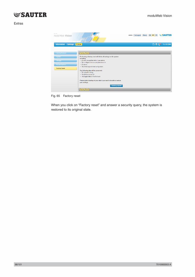
moduWeb Vision
98/101 7010083003 A98/101 7010083003 A
Extras
Fig. 65 Factory reset
When you click on “Factory reset” and answer a security query, the system is restored to its original state.

moduWeb Vision
7010083003 A 99/1017010083003 A 99/101
Configuration and start-up
17. Configuration and start-up
17.1 ConnectionIn accordance with the product data sheet “moduWeb500: web server for BACnet network moduWeb Vision” PDS 96.005 and fitting instructions “EY-WS5000” P10006978 A.
17.1.1 Starting the moduWeb500 web serverAfter a restart, moduWeb Vision is initialised. moduWeb Vision reports all the data points alarms and notifications for the BACnet devices. This process can take several minutes. moduWeb Vision can only operate correctly once the initialisation has been completed.
1. Turn the switch on the moduWeb500 to ON. The “STATUS” LED lights up red.
2. Wait 2 minutes until the system loads and the “STATUS” LED lights up green.
The system is ready.Loading may take longer, depending on the capacity of the SD card.If someone logs into moduWeb Vision from a PC before loading is completed, the browser displays a waiting screen.
( User who are logged in as administrators can also use the restart function in moduWeb; section 16.4 “Restart system”.
17.1.2 LED indicatorsThree LEDs on the moduWeb500 indicate its various operating states.The following table explains the function of each LED.
LED Status Description
STATUS Constant orange light moduWeb500 in startup mode
Constant green light moduWeb500 in operation
Flashing green Identification via CASE Sun “Blink”
Flashing red moduWeb500 in configuration, restart / download mode
Rapid flashing red Internal error
Left Ethernet LED
Constant orange light Network connection present
Off (no display) Network connection interrupted
Right Ethernet LED
Pulsating green Ethernet (data transmission active)
17.1.3 Reset buttonYou can use a button to reset the moduWeb500. The button is attached in such a away that is cannot be pressed inadvertently. The button has two functions:
1. Press the button for less than 5 seconds: warm start. The application is closed and restarted without interrupting the power supply.
2. Press the button for longer than 5 seconds: cold start. The power supply to the main CPU is switched off and on again.

moduWeb Vision
100/101 7010083003 A100/101 7010083003 A
Configuration and start-up
17.1.4 WatchdogA watchdog signal which monitors internal processes can be captured from the moduWeb500.
As a practical application, the signal can be connected directly to a digital or universal input of an automation station and monitored using software.
17.1.5 Switching off and disconnecting the moduWeb500 web server from the mains
If you want to disconnect the modWeb500 from the mains, use the following procedure to avoid data loss or disruption to the system.
1. Save all the changes made in moduWeb Vision.2. Log out3. Turn the switch on the moduWeb500 to OFF.
The indicator lamp flashes red.4. Wait until the indicator lamp goes out.
You can now disconnect the modWeb500 from the mains.

© Fr. Sauter AGIm Surinam 55CH-4016 BaselTel. +41 61 - 695 55 55Fax +41 61 - 695 55 [email protected] P
rint
ed in
Sw
itzer
land