operator’s · pdf filevolvo penta marine engines are used all over the world today. ......
TRANSCRIPT

OPERATOR’S MANUAL TAMD63L/P, TAMD74A

CALIFORNIA
Proposition 65 Warning
Diesel engine exhaust and some of its constituents are knownto the State of California to cause cancer, birth defects, andother reproductive harm.
This operator’s manual is also available in the following languages:
Diese Betriebsanleitung ist auch aufDeutsch erhältlich.Ein Bestellcoupon ist am Ende der Betriebs-anleitung zu finden.
Ce manuel d’instructions peut êtrecommandé en français.Vous trouverez un bon de commande à la findu manuel d’instructions.
Este libro de instrucciones puede soli-citarse en español.El cupón de pedido se encuentra al final dellibro.
Den här instruktionsboken kan bestäl-las på svenska.Beställningskupong finns i slutet av instrukti-onsboken.
Questo manuale d’istruzioni può esse-re ordinato in lingua italiana.Il tagliando per l’ordinazione è riportato allafine del manuale.
Dit instructieboek kan worden besteldin het Nederlands.De bestelcoupon vindt u achter in het instruc-tieboek.
Denne instruktionsbog kan bestillespå dansk.Bestillingskupon findes i slutningen af instruk-tionsbogen.
Tämän ohjekirjan voi tilata myös suo-menkielisenä.Tilauskuponki on ohjekirjan lopussa.
Este manual de instruções pode serencomendado em português.O talão de requerimento encontra-se no fimdo manual.
Áõôü ôï åã÷åéñßäéï ÷ñÞóçòäéáôßèåôáé óôçí áããëéêÞ ãëþóóá.Ãéá íá ðáñáããåßëåôå Ýíá áíôßôõðï,óõìðëçñþóôå ôç öüñìá ðïõ âñßóêåôáé óôïôÝëïò áõôïý ôïõ åã÷åéñéäßïõ ÷ñÞóçò.

ForewordVolvo Penta marine engines are used all over the world today. They are used in allpossible operating conditions for professional as well as leisure purposes. That’s notsurprising.
After more than 90 years as an engine manufacturer and after delivering over500,000 marine engines, the Volvo Penta name has become a symbol of reliability,technical innovation, top of the range performance and long service life. We also be-lieve that this is what you demand and expect of your Volvo Penta engine.
We would like you to read this operator’s manual thoroughly and consider the advicewe give on running and maintenance before you cast off on your maiden voyage sothat you will be ensured of fulfilling your expectations.
With warm regards
AB VOLVO PENTA
IMPORTANT! These instructions do not contain descriptions of controls oroperation for boats with waterjet. If your boat is equipped with Volvo Pentawaterjet, this information can be found in the operator’s manual that camewith the waterjet.
2
Contents
Safety information .............................................. 3
Boat trips ............................................................ 4
Maintenance and service .................................... 6
Introduction ........................................................ 8
Environmental responsibility ............................... 8
Running in .......................................................... 8
Fuel and oil ......................................................... 8
Service and spare parts ...................................... 8
Certified engines ................................................. 9
Warranty ............................................................. 9
Identification number .......................................... 11
Presentation ........................................................ 11
Instruments......................................................... 13
Instrument panels ............................................... 13
Control panels .................................................... 14
Warning displays ................................................ 14
Starting switch .................................................... 15
Controls ............................................................... 16
Single lever control ............................................. 16
Dual lever control ................................................ 17
Starting the engine ............................................. 18
Measures before start ......................................... 18
Starting procedure .............................................. 18
Operation ............................................................ 20
Check the instruments ........................................ 20
Alarms and fault indication .................................. 20
Cruising speed ................................................... 21
Manoeuvring ....................................................... 21
Accessories ........................................................ 23
Stopping the engine ........................................... 24
Before stopping .................................................. 24
Stop .................................................................... 24
Emergency stop ................................................. 24
After stopping ..................................................... 25
Anti-freezing measures ....................................... 25
Breaks in operation ............................................. 25
Maintenance schedule ....................................... 26
Maintenance ........................................................ 29
Engine, general .................................................. 29
Lubricating system.............................................. 32
Freshwater system ............................................. 35
Seawater system ................................................ 43
Fuel system ........................................................ 47
Electrical system ................................................ 52
Electrical component diagrams ........................... 56
Reverse gear ...................................................... 58
Inhibiting ............................................................. 60
Troubleshooting ................................................. 62
Start using auxiliary batteries .............................. 63
Technical Data .................................................... 64
Engine ................................................................ 64
Reverse gear ...................................................... 65
© 2001 AB VOLVO PENTAWe reserve the right to make revisions. Printed on environment-friendly paper(Cover: National Administration of Shipping and Navigation, permit 9809095)
3
Safety informationRead this chapter thoroughly. It concerns your safety. This section describes how safety information is presentedin this manual and on the product. It also includes a summary of basic safety regulations for boat trips and main-tenance of the engine.
Make sure you are in possession of the right operator’s manual before reading on. If this is not the case,please get in touch with your Volvo Penta dealer.
Incorrect handling can cause personal injury or damage to the product and/or property.Consequently, please read this operator’s manual thoroughly before starting the engineor carrying out maintenance and service. If anything is still not clear or if you are not sureof any points, please get in touch with your Volvo Penta dealer for assistance.
This symbol is used throughout the operator’s manual and on the product to bring your atten-tion to points of safety-related information. Always read such information thoroughly.
Warnings in the operator’s manual have the following order of priority:
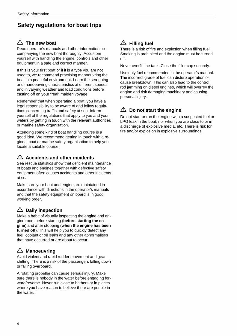
WARNING! Warns for the risk of physical injury, severe damage to the product or otherproperty or serious malfunctions that may occur if the instructions are not followed.
IMPORTANT! Used to call your attention to points that may cause malfunctions or damageto the product or other property.
NOTE! Used to call your attention to important information that can facilitate working meth-ods or handling.
This symbol is used in certain cases on our products to refer to important information foundin the operator’s manual. Make sure all warning and information symbols on the engine andtransmission are easily visible and legible. Replace symbols that have been damaged orpainted over.
4
Safety information
Safety regulations for boat trips
The new boatRead operator’s manuals and other information ac-companying the new boat thoroughly. Accustomyourself with handling the engine, controls and otherequipment in a safe and correct manner.
If this is your first boat or if it is a type you are notused to, we recommend practising manoeuvring theboat in a peaceful environment. Learn the sea-goingand manoeuvring characteristics at different speedsand in varying weather and load conditions beforecasting off on your “real” maiden voyage.
Remember that when operating a boat, you have alegal responsibility to be aware of and follow regula-tions concerning traffic and safety at sea. Informyourself of the regulations that apply to you and yourwaters by getting in touch with the relevant authoritiesor marine safety organisation.
Attending some kind of boat handling course is agood idea. We recommend getting in touch with a re-gional boat or marine safety organisation to help youlocate a suitable course.
Accidents and other incidentsSea rescue statistics show that deficient maintenanceof boats and engines together with defective safetyequipment often causes accidents and other incidentsat sea.
Make sure your boat and engine are maintained inaccordance with directions in the operator’s manualsand that the safety equipment on board is in goodworking order.
Daily inspectionMake a habit of visually inspecting the engine and en-gine room before starting (before starting the en-gine ) and after stopping (when the engine has beenturned off ). This will help you to quickly detect anyfuel, coolant or oil leaks and any other abnormalitiesthat have occurred or are about to occur.
ManoeuvringAvoid violent and rapid rudder movement and gearshifting. There is a risk of the passengers falling downor falling overboard.
A rotating propeller can cause serious injury. Makesure there is nobody in the water before engaging for-ward/reverse. Never run close to bathers or in placeswhere you have reason to believe there are people inthe water.
Filling fuelThere is a risk of fire and explosion when filling fuel.Smoking is prohibited and the engine must be turnedoff.
Never overfill the tank. Close the filler cap securely.
Use only fuel recommended in the operator’s manual.The incorrect grade of fuel can disturb operation orcause breakdown. This can also lead to the controlrod jamming on diesel engines, which will overrev theengine and risk damaging machinery and causingpersonal injury.
Do not start the engineDo not start or run the engine with a suspected fuel orLPG leak in the boat, nor when you are close to or ina discharge of explosive media, etc. There is risk forfire and/or explosion in explosive surroundings.
5
Safety information
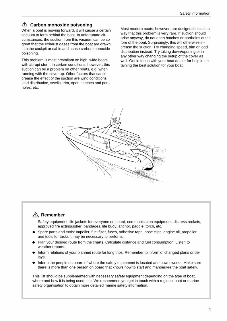
Carbon monoxide poisoningWhen a boat is moving forward, it will cause a certainvacuum to form behind the boat. In unfortunate cir-cumstances, the suction from this vacuum can be sogreat that the exhaust gases from the boat are drawninto the cockpit or cabin and cause carbon monoxidepoisoning.
This problem is most prevailant on high, wide boatswith abrupt stern. In certain conditions, however, thissuction can be a problem on other boats, e.g. whenrunning with the cover up. Other factors that can in-crease the effect of the suction are wind conditions,load distribution, swells, trim, open hatches and port-holes, etc.
Most modern boats, however, are designed in such away that this problem is very rare. If suction shouldarise anyway, do not open hatches or portholes at thefore of the boat. Surprisingly, this will otherwise in-crease the suction. Try changing speed, trim or loaddistribution instead. Try taking down/opening or inany other way changing the setup of the cover aswell. Get in touch with your boat dealer for help in ob-taining the best solution for your boat.
RememberSafety equipment: life jackets for everyone on board, communication equipment, distress rockets,approved fire extinguisher, bandages, life buoy, anchor, paddle, torch, etc.
l Spare parts and tools: Impeller, fuel filter, fuses, adhesive tape, hose clips, engine oil, propellerand tools for tasks it may be necessary to perform.
l Plan your desired route from the charts. Calculate distance and fuel consumption. Listen toweather reports.
l Inform relations of your planned route for long trips. Remember to inform of changed plans or de-lays.
l Inform the people on board of where the safety equipment is located and how it works. Make surethere is more than one person on board that knows how to start and manoeuvre the boat safely.
This list should be supplemented with necessary safety equipment depending on the type of boat,where and how it is being used, etc. We recommend you get in touch with a regional boat or marinesafety organisation to obtain more detailed marine safety information.
6
Safety information
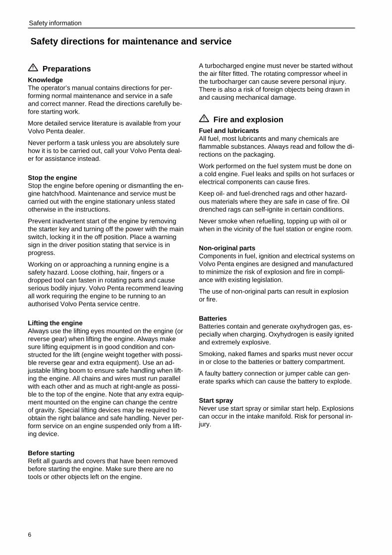
Safety directions for maintenance and service
PreparationsKnowledgeThe operator’s manual contains directions for per-forming normal maintenance and service in a safeand correct manner. Read the directions carefully be-fore starting work.
More detailed service literature is available from yourVolvo Penta dealer.
Never perform a task unless you are absolutely surehow it is to be carried out, call your Volvo Penta deal-er for assistance instead.
Stop the engineStop the engine before opening or dismantling the en-gine hatch/hood. Maintenance and service must becarried out with the engine stationary unless statedotherwise in the instructions.
Prevent inadvertent start of the engine by removingthe starter key and turning off the power with the mainswitch, locking it in the off position. Place a warningsign in the driver position stating that service is inprogress.
Working on or approaching a running engine is asafety hazard. Loose clothing, hair, fingers or adropped tool can fasten in rotating parts and causeserious bodily injury. Volvo Penta recommend leavingall work requiring the engine to be running to anauthorised Volvo Penta service centre.
Lifting the engineAlways use the lifting eyes mounted on the engine (orreverse gear) when lifting the engine. Always makesure lifting equipment is in good condition and con-structed for the lift (engine weight together with possi-ble reverse gear and extra equipment). Use an ad-justable lifting boom to ensure safe handling when lift-ing the engine. All chains and wires must run parallelwith each other and as much at right-angle as possi-ble to the top of the engine. Note that any extra equip-ment mounted on the engine can change the centreof gravity. Special lifting devices may be required toobtain the right balance and safe handling. Never per-form service on an engine suspended only from a lift-ing device.
Before startingRefit all guards and covers that have been removedbefore starting the engine. Make sure there are notools or other objects left on the engine.
A turbocharged engine must never be started withoutthe air filter fitted. The rotating compressor wheel inthe turbocharger can cause severe personal injury.There is also a risk of foreign objects being drawn inand causing mechanical damage.
Fire and explosionFuel and lubricantsAll fuel, most lubricants and many chemicals areflammable substances. Always read and follow the di-rections on the packaging.
Work performed on the fuel system must be done ona cold engine. Fuel leaks and spills on hot surfaces orelectrical components can cause fires.
Keep oil- and fuel-drenched rags and other hazard-ous materials where they are safe in case of fire. Oildrenched rags can self-ignite in certain conditions.
Never smoke when refuelling, topping up with oil orwhen in the vicinity of the fuel station or engine room.
Non-original partsComponents in fuel, ignition and electrical systems onVolvo Penta engines are designed and manufacturedto minimize the risk of explosion and fire in compli-ance with existing legislation.
The use of non-original parts can result in explosionor fire.
BatteriesBatteries contain and generate oxyhydrogen gas, es-pecially when charging. Oxyhydrogen is easily ignitedand extremely explosive.
Smoking, naked flames and sparks must never occurin or close to the batteries or battery compartment.
A faulty battery connection or jumper cable can gen-erate sparks which can cause the battery to explode.
Start sprayNever use start spray or similar start help. Explosionscan occur in the intake manifold. Risk for personal in-jury.

7
Safety information
Hot surfaces and fluidsA hot engine always involves risk for burn injuries.Take care with hot surfaces. E.g.: exhaust manifold,turbocharger, oil pan, charge air pipe, starting heater,hot coolant and warm lubricant in pipes and hoses.
Carbon monoxide poisoningStart the engine in well ventilated spaces only. Whenrunning in confined spaces, the exhaust gases andcrankcase gases must be evacuated.
ChemicalsMost chemicals such as glycol, anti-corrosion agent,preservatives, degreasing agent, etc., are hazardousto health. Always read and follow the directions onthe packaging.
Certain chemicals such as preservatives are flamma-ble and harmful to inhale. Provide good ventilationand use breathing protection when spraying. Alwaysread and follow the directions on the packaging.
Store chemicals and other hazardous materials out ofreach of children. Leave left over or used chemicalsto a destruction plant.
Cooling systemThere is a risk of water entering when working on theseawater system. Therefore, stop the engine andclose the sea cock before starting work.
Avoid opening the coolant filler cap when the engineis warm. Steam or hot coolant may spurt out andcause burn injuries.
If the filler cap, coolant pipe, cock, etc., must never-theless be opened or dismantled while the engine iswarm, the filler cap must be opened carefully to re-lease the pressure before removing it completely andstarting work. Note that the coolant can still be hotand cause burn injuries.
Lubricating systemHot oil can cause burn injuries. Avoid skin contactwith warm oil. Make sure the lubricating system isdepressurised before starting work. Never start or runthe engine with the oil filler cap removed or there willbe a risk of the oil being thrown out.
Fuel systemAlways protect your hands when carrying out leak de-tection. Escaping fluids under pressure can piercebodily tissue and cause serious injury. Risk of bloodpoisoning.
Always cover the alternator if it is located under thefuel filter. Fuel spills can damage the alternator.
Electrical system
Turn off the powerBefore starting work on the electrical system, the en-gine must be stopped and the powered turned off withthe main switch/switches. Shore power to the engineheater, battery charger or other extra equipment fittedto the engine must be disconnected.
BatteriesBatteries contain a highly corrosive electrolyte. Pro-tect your eyes, skin and clothing when charging andhanding batteries. Always use protective goggles andgloves.
In case of splashes on the skin, wash with soap andplenty of water. In case of splashes in the eyes, rinseimmediately with plenty of water and call a doctor.
8
IntroductionThe operator’s manual has been produced to give you the greatest benefit of your Volvo Penta marine engine. Itcontains the information necessary to handle and maintain your engine in a safe and correct manner. We wouldlike you to read this operator’s manual thoroughly and learn how to handle the engine, controls and other equip-ment in a safe manner before casting off for your maiden voyage.
Keep the operator’s manual handy at all times. Keep it safe and do not forget to hand it over to the new owner ifyou ever sell your boat.
Care of the environmentWe would all like to live in a clean and healthy envi-ronment. Somewhere where we can breathe cleanair, see healthy trees, have clean water in our lakesand oceans, and are able to enjoy the sunshine with-out being worried about our health. Unfortunately, thiscannot be taken for granted nowadays but is some-thing we must work together to achieve.
As a manufacturer of marine engines, Volvo Pentahas a special responsibility, why care of the environ-ment is a core value in our product development. To-day, Volvo Penta has a broad range of engines whereprogress has been made in reducing exhaust emis-sions, fuel consumption, engine noise, etc.
We hope you will take care in preserving these quali-ties. Always follow any advice given in the operator’smanual concerning fuel grades, operation and main-tenance and you will avoid causing unnecessary in-terference to the environment. Get in touch with yourVolvo Penta dealer if you notice any changes such asincreased fuel consumption exhaust smoke.
Adapt speed and distance to avoid wash and noisedisturbing or injuring animal life, moored boats, jetties,etc. Leave islands and harbours in the same condi-tion as you want to find them. Remember to alwaysleave hazardous waste such as waste oil, coolant,paint and wash residue, flat batteries, etc., for dis-posal at a destruction plant.
Our joint efforts will make a valuable contribution toour environment.
Running inThe engine must be “run in” during the first 10 hoursof operation as follows:
Run the engine under normal operation. Do not run itat full power except for short periods. Never run theengine for long periods at constant rpm during thistime.
A high consumption of lubricant is normal during therunning in period. Therefore, check the oil level moreoften than recommended.
The prescribed warranty inspection “First Service In-spection” must be carried out during this first period ofoperation. For more information: See Warranty andService Book.
Fuel and oilUse only fuel and oil grades as recommended in theoperator’s manual. Other grades can cause opera-tional problems, increase fuel consumption and havelong-range effects on engine service life.
Always change oil, oil filter and fuel filter according toprescribed intervals.
Service and spare partsVolvo Penta marine engines are designed for highoperational reliability and long service life. They areconstructed to withstand the marine environmentwhile also affecting it as little as possible. Throughregular service and the use of Volvo Penta originalspare parts, these qualities will be retained.
The worldwide Volvo Penta network of authoriseddealers is at your service. They are specialists inVolvo Penta products and stock accessories, originalspare parts, test equipment and the special tools re-quired to perform high-quality service and repairs.
Always follow the maintenance intervals specified inthe operator’s manual and remember to specify theengine/transmission number when ordering serviceand spare parts.

9
Introduction
Certified enginesIt is essential that owners and operators of emissioncertified engines used in areas where exhaust emis-sions are regulated by law are aware of the followingpoints:
A certification involves the engine type beingchecked and approved by applicable authorities. En-gine manufacturers guarantee that all engines of thesame type correspond with the certified engine.
This puts special demands on the maintenanceand service of your engine:
l Maintenance and service intervals recommendedby Volvo Penta must be followed.
l Only Volvo Penta original spare parts may beused.
l Service of injector pumps, pump settings and in-jectors must always be performed at anauthorised Volvo Penta workshop.
l The engine must not be modified in any way withthe exception of accessories and service kits ap-proved by Volvo Penta for use on the engine.
l Installation modifications must not be made to theengine exhaust pipe or inlet channels.
l Any sealed sections must not be broken by any-one other than authorised personnel.
Otherwise, the general directions concerning running,care and maintenance given in the operator’s manualapply.
IMPORTANT! Neglected or deficient mainte-nance/service and the use of non-original spareparts will entail Volvo Penta renouncing any re-sponsibility for the engine corresponding to thecertified version. Volvo Penta will not compen-sate for damage and/or costs arising from theabove.
WarrantyYour new Volvo Penta marine engine is covered by a limited warranty complying with the conditionsand instructions given in the Warranty and Service Book.
Note that AB Volvo Penta’s responsibility is limited to what is specified in the Warranty and ServiceBook. Read it carefully as soon as possible after delivery. It contains important information concerningthe warranty card, service, maintenance and what the owner is responsible to be aware of, check andperform. Warranty liability will otherwise be declined completely or fully by AB Volvo Penta.
Get in touch with your Volvo Penta dealer if you have not received a Warranty and Service Bookor a copy of the warranty card.

10
Introduction
Identification numberType plates with identification number can be found on the engine and transmission. This information must al-ways be used as a reference when ordering service and spare parts. Similar plates can probably be found onyour boat and its equipment. Make a note of the information in the space below and make a copy of this page sothe information is available even if the boat should be stolen.
The appearance and location of the type plates is shown below. The numbers in brackets refer to the location ofthe identification number on the type plate.
Engine
Product designation (1) ......................................................................................................
Serial and basic engine number (2) ....................................................................................
Product number (3) .............................................................................................................
Certification, IMO
Decal, part No. (4) ...............................................................................................................
Approval No. (5) ..................................................................................................................
Transmission
Product designation (6) .......................................................................................................
Serial number (7) .................................................................................................................
Product number (8) ..............................................................................................................
Engine and transmission decal
Reverse gear plate
Certification decal
Engine plate
Certification plate
(6)(7)
(8)
XXXX (6)
XXXXXXXXXX (7)
IMPORTANT ENGINE INFORMATION
AB Volvo Penta, Sweden VP xxxx (4)
IMO
ENGINE FAMILY xxxx ENGINE MODEL xxxx (1)TEST CYCLES xxxx POWER (kW/RPM) xxxx
IMO APP NO. MTC xxxx (5)
IMO APP NO. EPA –ENGINE SERIAL NO. AVAILABLE ON ENGINE IDENTIFICATION PLATECERTIFICATE AND TECHNICAL FILE: AVAILABLE ON WWW.PENTA.VOLVO.SE
THIS ENGINE IS CERTIFIED BY SWEDISH ACCREDITED ORGANISATION MTCIN ACCORDANCE WITH IMO NOX TECHNICAL CODE ANNEX VI MARPOL 73/78

11
PresentationTAMD63L, TAMD63P and TAMD74A are in-line,direct injection, 6-cylinder, 4-stroke marine dieselengines. They are equipped with turbocharger and fit-ted with either a heat exchanger for thermostat-regulated freshwater cooling or connections for keelcooling.
The engines are equipped with a seawater cooledcharge air cooler. The charge air cooler lowers thetemperature of the inlet air to the engine after it hasbeen compressed in the turbocharger. This allowshigh power output while keeping combustion andexhaust temperatures at a suitable level.
The exhaust manifold and turbocharger are fresh-water cooled to reduce heat radiation to the engineroom.
These engines are equipped with mechanical fuelcontrol.
TAMD63L-A, TAMD63L-B, TAMD63P-A
1. Fuel fine filters2. Smoke limiter3. Coolant filler cap4. Injection pump5. Oil filler cap6. Distribution box with semi-automatic
fuses7. Turbocharger8. Water cooled exhaust pipe elbow
(option)9. Reverse gear (ZF (MPM) IRM 220A-1)
10. Wastegate valve (TAMD63P)11. Oil dipstick, engine12. Fuel shut-off valve13. Oil cooler, engine14. Flexible engine mounting (option)
TAMD63L-A, TAMD63L-B, TAMD63P-A
1. Filter for crankcase ventilation2. Air filter3. Charge air cooler4. Oil filler cap5. Expansion tank6. Coolant filler cap7. Heat exchanger8. Alternator9. Sea water pump
10. By-pass filter for engine oil11. Oil filter, engine12. Starter motor13. Oil dipstick, engine14. Oil dipstick, reverse gear
14 13 12 11 10 9
1 2 3 4 5 6 7 8
1 2 3 4 5 6 7 8
14 13 12 11 10 9

12
Presentation
TAMD74A-A, TAMD74A-B
1. Fuel fine filters2. Smoke limiter3. Oil filler cap4. Coolant filler cap5. Injection pump6. Distribution box with semi-automatic
fuses7. Turbocharger*8. Exhaust pipe elbow9. Oil dipstick, engine
10. Fuel shut-off valve11. Oil cooler, engine12. Flexible engine mounting (option)13. Reverse gear (TD MG5091DC)
* TAMD74A-B: With wastegate.
TAMD74A-A, TAMD74A-B
1. Air filter2. Charge air cooler3. Expansion tank4. Heat exchanger5. Coolant filler cap6. Oil filler cap7. Alternator8. Starter motor9. Oil sump
10. Oil filter, engine11. By-pass filter for engine oil12. Sea water pump
1 2 3 4 5 6 7
8 9 10 11 12
1 2 3 4 5 6 7 8
9 10 11 12 13
13
InstrumentsThis chapter describes the Volvo Penta instruments that are available for your engine. Note that that tachometer,oil gauge, temperature gauge, charge gauge, starting switch, etc., that are shown here as panel mounted may bemounted separately in some boats.
If your boat is fitted with instruments not described here and you are not sure of their function, please get in touchwith your boat dealer.
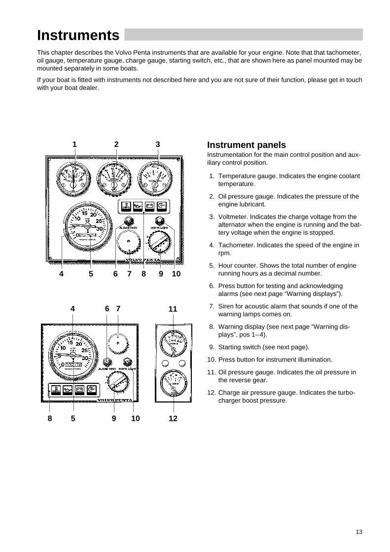
Instrument panelsInstrumentation for the main control position and aux-iliary control position.
1. Temperature gauge. Indicates the engine coolanttemperature.
2. Oil pressure gauge. Indicates the pressure of theengine lubricant.
3. Voltmeter. Indicates the charge voltage from thealternator when the engine is running and the bat-tery voltage when the engine is stopped.
4. Tachometer. Indicates the speed of the engine inrpm.
5. Hour counter. Shows the total number of enginerunning hours as a decimal number.
6. Press button for testing and acknowledgingalarms (see next page “Warning displays”).
7. Siren for acoustic alarm that sounds if one of thewarning lamps comes on.
8. Warning display (see next page “Warning dis-plays”, pos 1–4).
9. Starting switch (see next page).
10. Press button for instrument illumination.
11. Oil pressure gauge. Indicates the oil pressure inthe reverse gear.
12. Charge air pressure gauge. Indicates the turbo-charger boost pressure.
1 2 3
4 5 6 7 8 9 10
8 5 9 10
4 6 7 11
12
14
Instruments
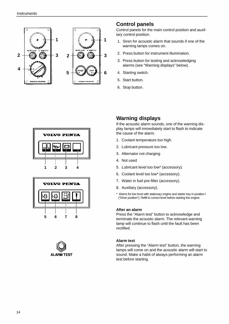
Control panelsControl panels for the main control position and auxil-iary control position.
1. Siren for acoustic alarm that sounds if one of thewarning lamps comes on.
2. Press button for instrument illumination.
3. Press button for testing and acknowledgingalarms (see “Warning displays” below).
4. Starting switch.
5. Start button.
6. Stop button.
Warning displaysIf the acoustic alarm sounds, one of the warning dis-play lamps will immediately start to flash to indicatethe cause of the alarm.
1. Coolant temperature too high.
2. Lubricant pressure too low.
3. Alternator not charging
4. Not used
5. Lubricant level too low* (accessory).
6. Coolant level too low* (accessory).
7. Water in fuel pre-filter (accessory).
8. Auxiliary (accessory).
* Warns for low level with stationary engine and starter key in position I(“Drive position”). Refill to correct level before starting the engine.
After an alarmPress the “Alarm test” button to acknowledge andterminate the acoustic alarm. The relevant warninglamp will continue to flash until the fault has beenrectified.
Alarm testAfter pressing the “Alarm test” button, the warninglamps will come on and the acoustic alarm will start tosound. Make a habit of always performing an alarmtest before starting.
1
2
4
3
5 6 7 8
5 6
2 3
1
1 2 3 4
15
Instruments
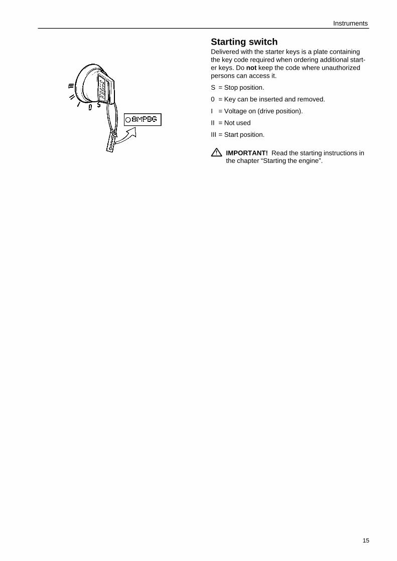
Starting switchDelivered with the starter keys is a plate containingthe key code required when ordering additional start-er keys. Do not keep the code where unauthorizedpersons can access it.
S = Stop position.
0 = Key can be inserted and removed.
I = Voltage on (drive position).
II = Not used
III = Start position.
IMPORTANT! Read the starting instructions inthe chapter “Starting the engine”.
16
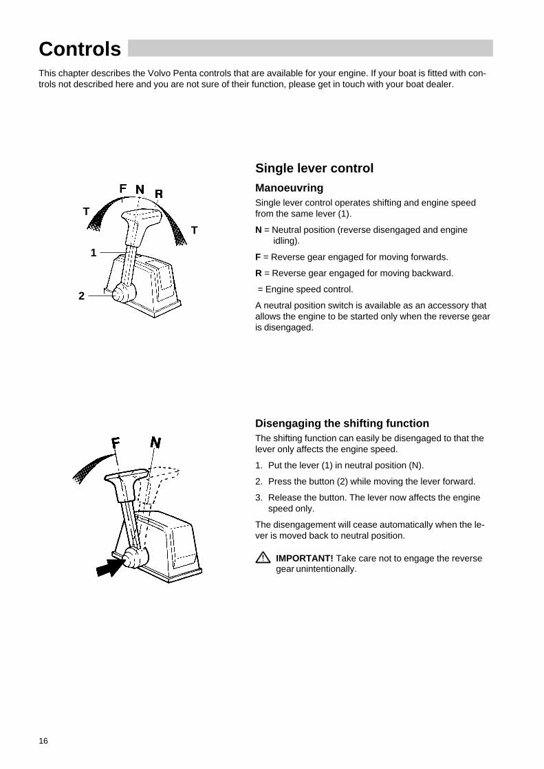
Single lever control
ManoeuvringSingle lever control operates shifting and engine speedfrom the same lever (1).
N = Neutral position (reverse disengaged and engineidling).
F = Reverse gear engaged for moving forwards.
R = Reverse gear engaged for moving backward.
= Engine speed control.
A neutral position switch is available as an accessory thatallows the engine to be started only when the reverse gearis disengaged.
ControlsThis chapter describes the Volvo Penta controls that are available for your engine. If your boat is fitted with con-trols not described here and you are not sure of their function, please get in touch with your boat dealer.
Disengaging the shifting functionThe shifting function can easily be disengaged to that thelever only affects the engine speed.
1. Put the lever (1) in neutral position (N).
2. Press the button (2) while moving the lever forward.
3. Release the button. The lever now affects the enginespeed only.
The disengagement will cease automatically when the le-ver is moved back to neutral position.
IMPORTANT! Take care not to engage the reversegear unintentionally.
T
T
2
1
17
Controls
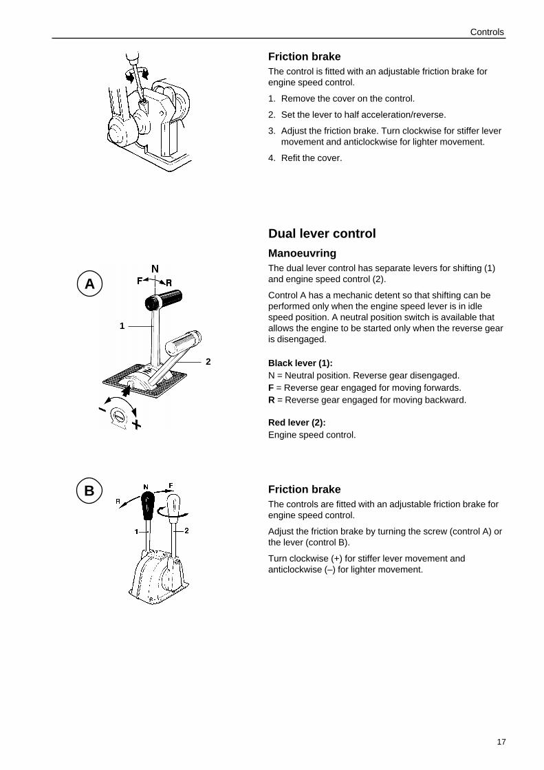
Friction brakeThe control is fitted with an adjustable friction brake forengine speed control.
1. Remove the cover on the control.
2. Set the lever to half acceleration/reverse.
3. Adjust the friction brake. Turn clockwise for stiffer levermovement and anticlockwise for lighter movement.
4. Refit the cover.
Dual lever control
ManoeuvringThe dual lever control has separate levers for shifting (1)and engine speed control (2).
Control A has a mechanic detent so that shifting can beperformed only when the engine speed lever is in idlespeed position. A neutral position switch is available thatallows the engine to be started only when the reverse gearis disengaged.
Black lever (1):N = Neutral position. Reverse gear disengaged.F = Reverse gear engaged for moving forwards.R = Reverse gear engaged for moving backward.
Red lever (2):Engine speed control.
Friction brakeThe controls are fitted with an adjustable friction brake forengine speed control.
Adjust the friction brake by turning the screw (control A) orthe lever (control B).
Turn clockwise (+) for stiffer lever movement andanticlockwise (–) for lighter movement.
B
A
2
1
18
Starting the engineMake a habit of “visually” inspecting the engine and engine room before starting This will help you to quickly de-tect abnormalities that have occurred or are about to occur. Make sure instruments and warning displays indicatenormal values after starting the engine.
We recommend installing a heater for the engine room to minimize start smoke when cold starting at tempera-tures below +5oC (41oF).
WARNING! Never use start spray or similar start help. Risk for explosion!
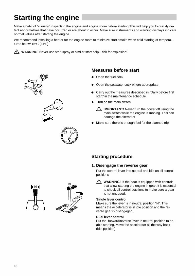
Measures before startl Open the fuel cock
l Open the seawater cock where appropriate
l Carry out the measures described in “Daily before firststart” in the maintenance schedule.
l Turn on the main switch
IMPORTANT! Never turn the power off using themain switch while the engine is running. This candamage the alternator.
l Make sure there is enough fuel for the planned trip.
Starting procedure
1. Disengage the reverse gearPut the control lever into neutral and idle on all controlpositions
WARNING! If the boat is equipped with controlsthat allow starting the engine in gear, it is essentialto check all control positions to make sure a gearis not engaged.
Single lever controlMake sure the lever is in neutral position “N”. Thismeans the accelerator is in idle position and the re-verse gear is disengaged.
Dual lever controlPut the forward/reverse lever in neutral position to en-able starting. Move the accelerator all the way back(idle position).

19
Starting the engine
2. Turn on the powerTurn on the power by putting the starter key in position“I”.
3. Check warning lamps and alarmsPress the “Alarm test” button on the instrument panelto make sure the warning lamps come on and theacoustic alarm sounds.
4. Start the engineStart using the starting switchTurn the key to position “III”. Release the key so it re-turns to “I” immediately after the engine has started.
IMPORTANT! If the starter motor has been en-gaged for the maximum time (30 seconds), it mustbe allowed to cool down for at least one minutebefore a new attempt is made at starting.
NOTE! The key must first be turned to “S” before mak-ing a new attempt at starting.
Start using the start buttonPress the start button. Release the button immediatelyafter the engine has started (note that when startingfrom the alternative control position, the starter key atthe main control position must be turned to “I”).
Start using auxiliary batteriesRefer to the description in the chapter “Troubleshoot-ing”.
5. Check the instruments and run the enginewarmLet the engine idle for the first ten seconds and makesure the instruments and warning display show normalvalues. Then run the engine at low speed and low loadso it attains normal operating temperature before usingfull power.
IMPORTANT! Do not race the engine when it iscold.
6. Check the oil level in the reverse gearThe oil level should be checked once the reverse gearhas attained operating temperature (see the descriptionin the chapter “Maintenance” under the heading “Re-verse gear”).

20
OperationLearn how to handle the engine, controls and other equipment in a safe and correct manner before casting off foryour maiden voyage.
WARNING! Avoid violent and rapid rudder movement and gear shifting. There is a risk of the passengersfalling down or falling overboard.
WARNING! A rotating propeller can cause serious injury. Make sure there is nobody in the water before en-gaging forward/reverse. Never run close to bathers or in places where you have reason to believe there arepeople in the water.
Check the instrumentsCheck the instruments and warning display directly afterstart and regularly during operation.
Oil pressure
During operation, the oil pressure gauge should show areading of 300–550 kPa (43.5–79.8 psi) or 450–650 kPa(65.3–94 psi) for TAMD63 respectively TAMD74. A lowervalue is normal at idling speed. The acoustic alarm willsound automatically in case of low oil pressure.
Coolant temperature
During operation, the temperature gauge should show areading of 75–90°C (167–194°F). The acoustic alarm willsound automatically in case the coolant temperature is toohigh.
Charging
During operation, the charge voltage gauge should show areading of 14V or 28V for a 12 respectively 24V system.The acoustic alarm will sound automatically in case thecharge voltage is missing.
Alarms and fault indicationIf the acoustic alarm sounds, one of the warning displaylamps will immediately start to flash to indicate the causeof the alarm: High coolant temperature (1), low oil pressure(2) and no charge voltage (3).
IMPORTANT! Stop the engine immediately after analarm for low oil pressure. Investigate the cause andrectify it.
Slow the engine speed to idle/disengaged after an alarmfor high coolant temperature. If temperature does not drop,the engine must be stopped. Investigate the cause andrectify it.
1 2 3
21
Operation
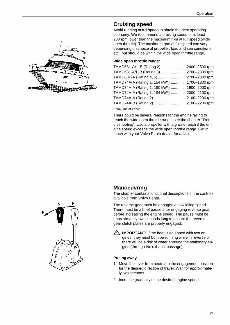
Cruising speedAvoid running at full speed to obtain the best operatingeconomy. We recommend a cruising speed of at least200 rpm lower than the maximum rpm at full speed (wideopen throttle). The maximum rpm at full speed can varydepending on choice of propeller, load and sea conditions,etc., but should be within the wide open throttle range.
Wide open throttle range:
TAMD63L-A/L-B (Rating 2) ..................... 2400–2500 rpmTAMD63L-A/L-B (Rating 3) ..................... 2700–2800 rpmTAMD63P-A (Rating 4, 5) ........................ 2700–2800 rpmTAMD74A-A (Rating 1, 154 kW*) ............ 1700–1800 rpmTAMD74A-A (Rating 1, 160 kW*) ............ 1900–2000 rpmTAMD74A-A (Rating 1, 184 kW*) ............ 2000–2100 rpmTAMD74A-A (Rating 2) ............................ 2100–2200 rpmTAMD74A-B (Rating 2) ............................ 2100–2200 rpm
* Max. motor effect.
There could be several reasons for the engine failing toreach the wide open throttle range, see the chapter “Trou-bleshooting”. Use a propeller with a greater pitch if the en-gine speed exceeds the wide open throttle range. Get intouch with your Volvo Penta dealer for advice.
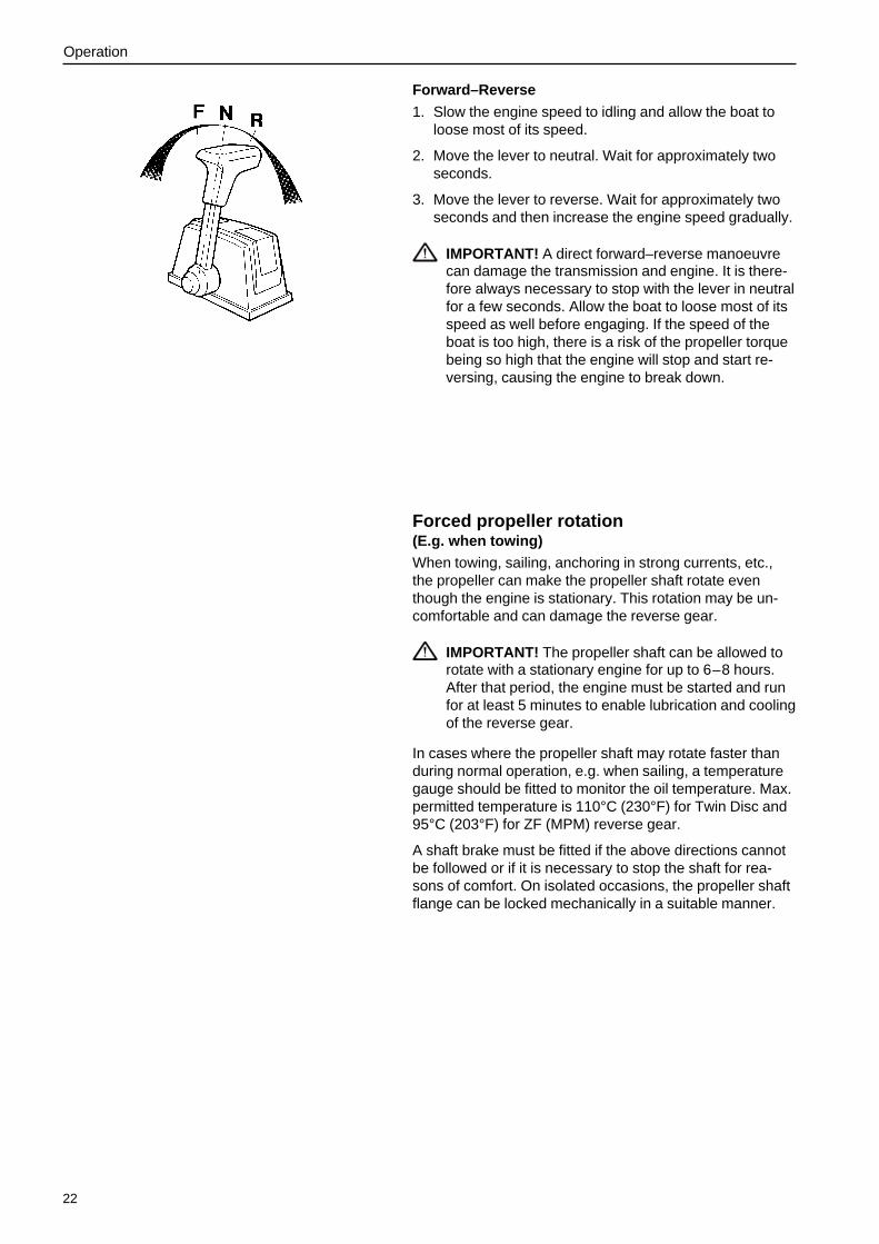
ManoeuvringThe chapter contains functional descriptions of the controlsavailable from Volvo Penta.
The reverse gear must be engaged at low idling speed.There must be a brief pause after engaging reverse gearbefore increasing the engine speed. The pause must beapproximately two seconds long to ensure the reversegear clutch plates are properly engaged.
IMPORTANT! If the boat is equipped with two en-gines, they must both be running while in reverse orthere will be a risk of water entering the stationary en-gine (through the exhaust passage).
Pulling away
1. Move the lever from neutral to the engagement positionfor the desired direction of travel. Wait for approximate-ly two seconds.
2. Increase gradually to the desired engine speed.
22
Operation
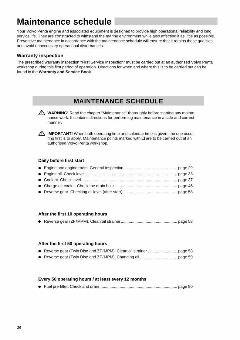
Forward–Reverse
1. Slow the engine speed to idling and allow the boat toloose most of its speed.
2. Move the lever to neutral. Wait for approximately twoseconds.
3. Move the lever to reverse. Wait for approximately twoseconds and then increase the engine speed gradually.
IMPORTANT! A direct forward–reverse manoeuvrecan damage the transmission and engine. It is there-fore always necessary to stop with the lever in neutralfor a few seconds. Allow the boat to loose most of itsspeed as well before engaging. If the speed of theboat is too high, there is a risk of the propeller torquebeing so high that the engine will stop and start re-versing, causing the engine to break down.
Forced propeller rotation(E.g. when towing)When towing, sailing, anchoring in strong currents, etc.,the propeller can make the propeller shaft rotate eventhough the engine is stationary. This rotation may be un-comfortable and can damage the reverse gear.
IMPORTANT! The propeller shaft can be allowed torotate with a stationary engine for up to 6–8 hours.After that period, the engine must be started and runfor at least 5 minutes to enable lubrication and coolingof the reverse gear.
In cases where the propeller shaft may rotate faster thanduring normal operation, e.g. when sailing, a temperaturegauge should be fitted to monitor the oil temperature. Max.permitted temperature is 110°C (230°F) for Twin Disc and95°C (203°F) for ZF (MPM) reverse gear.
A shaft brake must be fitted if the above directions cannotbe followed or if it is necessary to stop the shaft for rea-sons of comfort. On isolated occasions, the propeller shaftflange can be locked mechanically in a suitable manner.

23
Operation
Accessories
Trolling valveCertain Twin Disc reverse gears can be fitted with a trollingvalve so that the lowest speed of the boat can be variablyreduced by 1–80% at engine speeds up to 1100 rpm.
IMPORTANT! Risk of overheating the reverse gear ifthe trolling valve is used at higher engine speeds than1100 rpm.
Manoeuvring
Disengage the reverse gear and set the trolling valve formaximum slip. Engage “Forward” or “Reverse” and set thedesired slip position within the permitted engine speedrange.
In order to attain full propeller output, the trolling valvelever must always be in “disengaged” position when notbeing used.
Flush and bilge pumpThe bilge pump has a vacuum switch (1) that automaticallydisengages the pump when water is no longer being drawninto the pump.
The scavenging and bilge pump is engaged and disen-gaged from a switch that is normally located at the maincontrol position. The bilge pump can also be engagedmanually by holding down the lever 2 for about 20 sec-onds.

24
Stopping the engineLet the engine run at low idling speed (in neutral) for at least three minutes before turning it off. This will keep theengine temperature in balance and prevent it boiling.
IMPORTANT! The procedure described above is especially important if the engine has been run hard and/or exerted to heavy loads.
Stop1. Disengage the reverse gear by moving the lever to neu-
tral position.
2. Turn the key to stop position “S” or press the stop but-ton.
3. Hold the key/button in position until the engine hasstopped (the key will return to “0” automatically whenreleased and can then be removed).
Emergency stopIf a fault occurs that prevents the engine being stopped bythe normal method, it can be stopped manually using thelever on the injection pump. Pull back on the lever until theengine is stationary.
WARNING! Working on or approaching a running en-gine is a safety hazard. Beware of rotating parts andhot surfaces.
After stoppingl Check the engine and engine room for leaks.
l Close the fuel cock and seawater cock.
IMPORTANT! Do not forget to open the cocksbefore starting the engine again.
l Read off the hour counter and carry out preventivemaintenance according to the maintenance schedule.
l Turn off the main switch if the engine is not to be usedfor long periods.
IMPORTANT! Never turn the power off using themain switch while the engine is running. This candamage the alternator.

25
Stopping the engine
Anti-freezing measuresIf the engine room cannot be protected from frost, the sea-water system must be drained and the coolant in the fresh-water system must contain sufficient anti-freeze to preventit from freezing. Refer to chapter Maintenance “Seawatersystem” and “Freshwater system” respectively.
WARNING! If the seawater system bursts due tofreezing, it is possible for the boat to sink.
IMPORTANT! If the coolant does not give sufficientanti-freeze protection, it may cause costly damage tothe engine.Check the charge of the battery. A poorly chargedbattery can freeze and break.
Breaks in operationDuring breaks in operation when the boat is in the water,the engine must be run warm once a fortnight. This willprevent the engine from corroding.
IMPORTANT! The engine must be conserved if it isnot to be used for longer than two months: Refer to:Inhibiting
26
Maintenance scheduleYour Volvo Penta engine and associated equipment is designed to provide high operational reliability and longservice life. They are constructed to withstand the marine environment while also affecting it as little as possible.Preventive maintenance in accordance with the maintenance schedule will ensure that it retains these qualitiesand avoid unnecessary operational disturbances.
Warranty inspectionThe prescribed warranty inspection “First Service Inspection” must be carried out at an authorised Volvo Pentaworkshop during this first period of operation. Directions for when and where this is to be carried out can befound in the Warranty and Service Book .
MAINTENANCE SCHEDULE
WARNING! Read the chapter “Maintenance” thoroughly before starting any mainte-nance work. It contains directions for performing maintenance in a safe and correctmanner.
IMPORTANT! When both operating time and calendar time is given, the one occur-ring first is to apply. Maintenance points marked with are to be carried out at anauthorised Volvo Penta workshop.
Daily before first start
l Engine and engine room. General inspection ............................................... page 29
l Engine oil. Check level ................................................................................. page 33
l Coolant. Check level ..................................................................................... page 37
l Charge air cooler. Check the drain hole ....................................................... page 46
l Reverse gear. Checking oil level (after start) ................................................ page 58
After the first 10 operating hours
l Reverse gear (ZF/MPM). Clean oil strainer .................................................. page 58
After the first 50 operating hours
l Reverse gear (Twin Disc and ZF/MPM). Clean oil strainer .......................... page 58
l Reverse gear (Twin Disc and ZF/MPM). Changing oil ................................. page 59
Every 50 operating hours / at least every 12 months
l Fuel pre-filter. Check and drain .................................................................... page 50
27
Maintenance schedule
Every 25–200 operating hours 1) / at least every 12 months
l Engine oil. Change 1) .................................................................................... page 33
l Oil filter. Change 2) ........................................................................................ page 341) The oil change interval varies depending on the engine type, oil grade and sulphur content of
the fuel. See page 32.2) The oil filter is changed in every second oil change.
After the first 100 operating hours
Valve clearances. Check ...................................................................... not illustrated
Every 250 operating hours / at least every 12 months
l Crankcase ventilation(TAMD63). Change filter ............................................. page 30
l Drive belts (not Poly-V). Check / Adjustment ................................................ page 30
l Air filter (TAMD63). Clean ............................................................................ page 31
l Seawater filter. Check/clean ......................................................................... page 45
l Zinc anodes. Check/Change ........................................................................ page 45
l Fuel pre-filter(Double filter). Check1) ............................................................. page 49
l Electrical connections. Check/clean ............................................................. page 52
l Reverse gear (ZF/MPM). Clean oil strainer .................................................. page 581) Concerns only double filters: Check the manometer and change filter if necessary, but change
filter at least every 1000 operating hours or at least once at year.
Every 500 operating hours / at least every 12 months
l Drive belts(Poly V). Check / Adjustment ....................................................... page 30
l Coolant (Anti-corrosion mixture). Topping up1) ............................................. page 36
l Battery. Ceck of electrolyte ........................................................................... page 53
l Reverse gear (ZF/MPM). Changing oil ......................................................... page 591) This applies only if the cooling system is filled with an anti-corrosion mixture.
Every 1000 operating hours / at least every 12 months
Valve clearances. Check/Adjust ........................................................... not illustrated
l Air filter (TAMD74). Change ......................................................................... page 31
l Fuel filter. Change ........................................................................................ page 48
l Fuel pre-filter. Change filter element ............................................................. page 50
l Reverse gear (Twin Disc). Clean oil strainer ................................................ page 58
l Reverse gear (Twin Disc). Changing oil ....................................................... page 59

28
Maintenance schedule
Every 2000 operating hours
Injectors. Pressure test ......................................................................... not illustrated
Every 12 months
Turbocharger. Check ............................................................................ not illustrated
Wastegate (TAMD63P, TAMD74A-B). Check ...................................... not illustrated
Engine and reverse gear. General check ............................................. not illustrated
Heat exchanger. Check / Clean ............................................................ not illustrated
Charge air cooler. Check / Clean .......................................................... not illustrated
Oil cooler (Reverse gear). Check / Clean ............................................. not illustrated
l Impeller (Seawater pump). Check / Change ................................................. page 44
l Impeller (Flush pump/Bilge pump). Check / Change ............................ not illustrated
l Engine and reverse gear. Clean / Paint ................................................ not illustrated
Every 24 months
l Coolant. Change........................................................................................... page 37
l Cooling system. Flushing ............................................................................. page 39
Renovated engine:After the first 100 operating hours
Valve clearances. Check ...................................................................... not illustrated

29
MaintenanceThis chapter contains general technical information and directions for carrying out the prescribed maintenancepoints. Read the directions carefully before starting work. The times at which the maintenance points are to becarried out can be found in the previous chapter “Maintenance schedule”.
WARNING! Read the safety directions for maintenance and service in the chapter “Safety information” be-fore starting work.
WARNING! Maintenance and service must be carried out on a stationary engine unless specified other-wise. Stop the engine before opening or dismantling the engine hatch/hood. Prevent inadvertent start of theengine by removing the starter key and turning off the power with the main switch.
Engine, general
General inspectionMake a habit of “visually” inspecting the engine andengine room before starting the engine and afterstopping when the engine has been turned off. Thiswill help you to quickly detect abnormalities that haveoccurred or are about to occur.
Look especially carefully for oil, fuel and coolantleaks, loose bolts, worn or slack drive belts, looseconnections, damaged hoses and electric cables.This inspection takes only a few minutes but can pre-vent serious operating disturbances and costly re-pairs.
WARNING! Accumulations of fuel, oil andgrease on the engine or in the engine room is afire hazard and must be removed immediatelythey are detected.
IMPORTANT! If an oil, fuel or coolant leak is de-tected, the cause must be investigated and thefault rectified before the engine is started.
IMPORTANT! Never point high-pressure waterjets directly at seals, rubber hoses or electricalcomponents. Never use the high-pressure func-tion when washing the engine.

30
Maintenance: Engine, general
Crankcase ventilation. Change filter(TAMD63)Change the filter (1) earlier than recommended if oil isforced out of the relief valve (2).
1. Dismantle the filter (1) by screwing it anti-clock-wise.
2. Check the rubber gasket in the bracket andchange if necessary. Screw on the new filter byhand.
Drive belts. Check/Adjust/Change
WARNING! Stop the engine before commenc-ing maintenance work.
GeneralCheck belt tension and condition regularly. If the beltis too taut it can damage bearings and if it is too looseit may slip. Check and adjust after operation when thebelt is warm.
IMPORTANT! Always change a belt that ap-pears worn or is cracked (belts working in pairsmust be replaced together).
Poly-V beltThe alternator and circulation pump are driven by aPoly-V belt for best function and service life.A torque wrench must be used for adjustment.
1. Undo screws (A) before you tension the belt.
2. Change the belt as necessary.
3. Put the torque wrench stub into the square hole inthe jockey wheel bracket. Tension the belt with 60±3 Nm (6 ±0.3 kpm/44 ± 2 lbf.ft).
4. Tighten screws (A).
Other beltsAlso check the belts for the bilge and flushing pump,extra alternator etc. These are usually driven by con-ventional V- belts.
Adjust and change as necessary. It can generally besaid that these belts are correctly tensioned if theycan be pressed down 10 mm (3/8") by thumb pres-sure.
Clean the belt grooves before fitting a new belt.
31
Maintenance: Engine, general
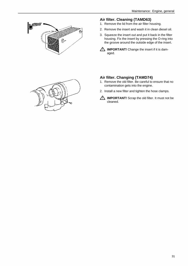
Air filter. Cleaning (TAMD63)1. Remove the lid from the air filter housing.
2. Remove the insert and wash it in clean diesel oil.
3. Squeeze the insert out and put it back in the filterhousing. Fix the insert by pressing the O-ring intothe groove around the outside edge of the insert.
IMPORTANT! Change the insert if it is dam-aged.
Air filter. Changing (TAMD74)1. Remove the old filter. Be careful to ensure that no
contamination gets into the engine.
2. Install a new filter and tighten the hose clamps.
IMPORTANT! Scrap the old filter. It must not becleaned.
32
Maintenance: Lubricating system
SAE5W/30
−−−−−30 −−−−−20 −−−−−10 ±0 +10 20 30 40
−−−−−22 −−−−− 4 +++++14 32 50 68 86 104
−−−−−15oC SAE15W/40
−−−−−25oC SAE10W/30
−−−−−10oC SAE20W/30
±0oC SAE30
SAE40+10oC
oC
oF
✱✱✱✱✱
Lubricating system
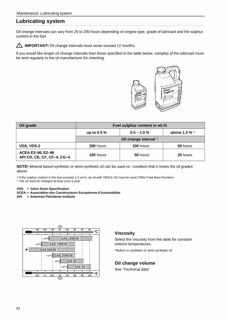
Oil change intervals can vary from 25 to 200 hours depending on engine type, grade of lubricant and the sulphurcontent in the fuel.
IMPORTANT! Oil change intervals must never exceed 12 months.
If you would like longer oil change intervals than those specified in the table below, samples of the lubricant mustbe sent regularly to the oil manufacturer for checking.
ViscositySelect the viscosity from the table for constantexterior temperatures.
*Refers to synthetic or semi-synthetic oil
Oil change volumeSee “Technical data”
NOTE! Mineral based synthetic or semi-synthetic oil can be used on condition that it meets the oil gradesabove.1) If the sulphur content in the fuel exceeds 1.0 wt.%, an oil with TBN14–20 must be used (TBN=Total Base Number)2) The oil must be changed at least once a year
VDS = Volvo Drain SpecificationACEA = Association des Constructeurs Européenne d'AutomobilesAPI = American Petroleum Institute
Oil grade Fuel sulphur content in wt.%
up to 0.5 % 0.5 – 1.0 % above 1.0 % 1)
Oil change interval 2)
VDS, VDS-2 200 hours 100 hours 50 hours
100 hours 50 hours 25 hoursACEA E3–96, E2–96API CD, CE, CF, CF–4, CG–4

33
Maintenance: Lubricating system
Engine oil. Check levelThe oil level must be within the marked range on thedipstick and must be checked daily before starting thefirst time.
Engine oil. ChangeAlways observe the recommended oil change in-terval. Use a manual or electric oil scavengingpump (optional equipment) to suck the oil out ofthe sump .
IMPORTANT! Only use recommended gradesof oil (see previous page).
1. Warm the engine up (this makes it easier to suckthe oil up from the sump). Then stop the engine.
WARNING! Hot oil and hot surfaces cancause burns.
2. TAMD63 (electric oil scavenging pump):Remove the dipstick. Connect the suction hose ofthe oil scavenging pump to the dipstick tube (1).Suck the oil out.
TAMD74 (manual oil scavenging pump):Connect a hose to the outlet pipe of the oil scav-enging pump. Suck the oil out.
3. Change the oil filter and the by-pass filter at everysecond oil change (please refer to the instructionon the next page).
4. Fill up with oil to the correct level.
Engine oil. FillingTop up the oil through the filler opening (1) in the ven-tilation cover. Make sure the correct level is attainedbut wait a few minutes to allow the oil to run into theoil sump.
IMPORTANT! Do not fill above the maximum oillevel. Use only oil of the recommended grade(see the previous page).
1
1
TAMD63
TAMD74
34
Maintenance: Lubricating system
5. Start the engine and allow it to idle. Check that thelow oil pressure warning lamp goes out and thatthere is no leakage by the filter.
WARNING! Approaching or working with arunning engine is a safety risk. Be careful toavoid rotating components and hot surfaces.
6. Stop the engine. Wait a few minutes before youcheck the oil level. Top up as necessary.
NOTE! Process the old oil filter in accordance with lo-cal regulations.
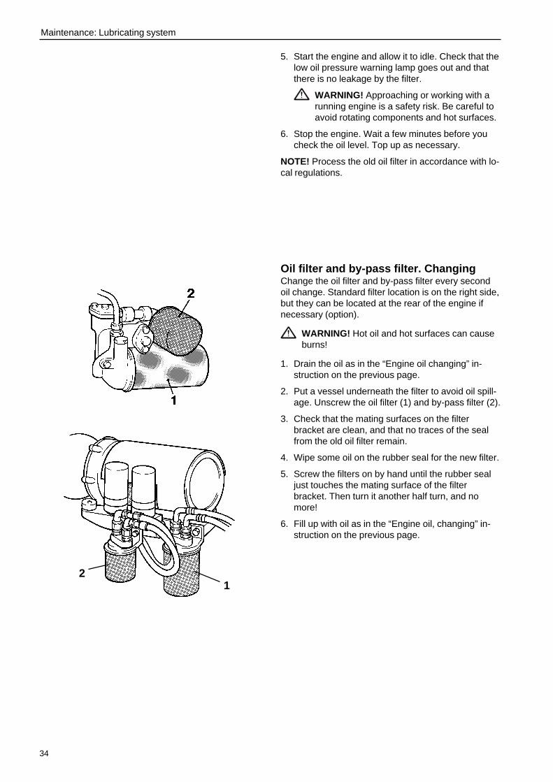
Oil filter and by-pass filter. ChangingChange the oil filter and by-pass filter every secondoil change. Standard filter location is on the right side,but they can be located at the rear of the engine ifnecessary (option).
WARNING! Hot oil and hot surfaces can causeburns!
1. Drain the oil as in the “Engine oil changing” in-struction on the previous page.
2. Put a vessel underneath the filter to avoid oil spill-age. Unscrew the oil filter (1) and by-pass filter (2).
3. Check that the mating surfaces on the filterbracket are clean, and that no traces of the sealfrom the old oil filter remain.
4. Wipe some oil on the rubber seal for the new filter.
5. Screw the filters on by hand until the rubber sealjust touches the mating surface of the filterbracket. Then turn it another half turn, and nomore!
6. Fill up with oil as in the “Engine oil, changing” in-struction on the previous page.
12

35
Maintenance: Freshwater system
Freshwater system
The freshwater system is the internal engine cooling system. It is a closed system and must always be filled witha coolant that protects it against internal corrosion and freezing when the climate demands.
The circulation pump ensure good circulation in the system. The thermostat will start to open at a certain temper-ature and will be fully open when the engine has attained normal operating temperature. When the thermostatopens, the warm coolant passes through the heat exchanger where it is cooled by the water in the engine’s sea-water system.
In its standard version, the engine is fitted with an internal freshwater system. Volvo Penta also supply engineswith the cooling system prepared for external cooling, e.g. keel cooling.
Coolant. GeneralThe freshwater system must always be filled with acoolant that protects it against internal corrosion andfreezing when the climate demands.
Anti-corrosive additives become less efficient withage and the coolant must therefore be changed.
IMPORTANT ! Never use only water as a cool-ant and change the coolant in accordance withthe recommendations in the maintenanceschedule.
Water qualityTo avoid clogging the system, the coolant must bemixed with pure water in accordance with ASTMD4985. If there are doubts about the purity of the wa-ter, use distilled water or ready-mixed coolant in-stead.
ASTM D4985:
Total solid particles ....................................... < 340 ppm
Total hardness ................................................ < 9.5° dH
Chloride ........................................................... < 40 ppm
Sulphate .......................................................... < 100 ppm
pH-value .......................................................... 5.5–9
Silicon ............................................................. < 20 mg SiO2/l
Iron ................................................................... < 0.10 ppm
Manganese ...................................................... < 0.05 ppm
Conductivity ................................................... < 500 µS/cm
Organic content, COD Mn ................................ < 15 mg KMnO4/l
36
Maintenance: Freshwater system
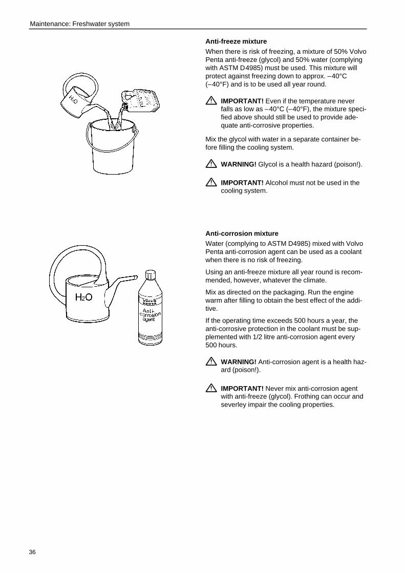
Anti-freeze mixture
When there is risk of freezing, a mixture of 50% VolvoPenta anti-freeze (glycol) and 50% water (complyingwith ASTM D4985) must be used. This mixture willprotect against freezing down to approx. –40°C(–40°F) and is to be used all year round.
IMPORTANT! Even if the temperature neverfalls as low as –40°C (–40°F), the mixture speci-fied above should still be used to provide ade-quate anti-corrosive properties.
Mix the glycol with water in a separate container be-fore filling the cooling system.
WARNING! Glycol is a health hazard (poison!).
IMPORTANT! Alcohol must not be used in thecooling system.
Anti-corrosion mixtureWater (complying to ASTM D4985) mixed with VolvoPenta anti-corrosion agent can be used as a coolantwhen there is no risk of freezing.
Using an anti-freeze mixture all year round is recom-mended, however, whatever the climate.
Mix as directed on the packaging. Run the enginewarm after filling to obtain the best effect of the addi-tive.
If the operating time exceeds 500 hours a year, theanti-corrosive protection in the coolant must be sup-plemented with 1/2 litre anti-corrosion agent every500 hours.
WARNING! Anti-corrosion agent is a health haz-ard (poison!).
IMPORTANT! Never mix anti-corrosion agentwith anti-freeze (glycol). Frothing can occur andseverley impair the cooling properties.
37
Maintenance: Freshwater system
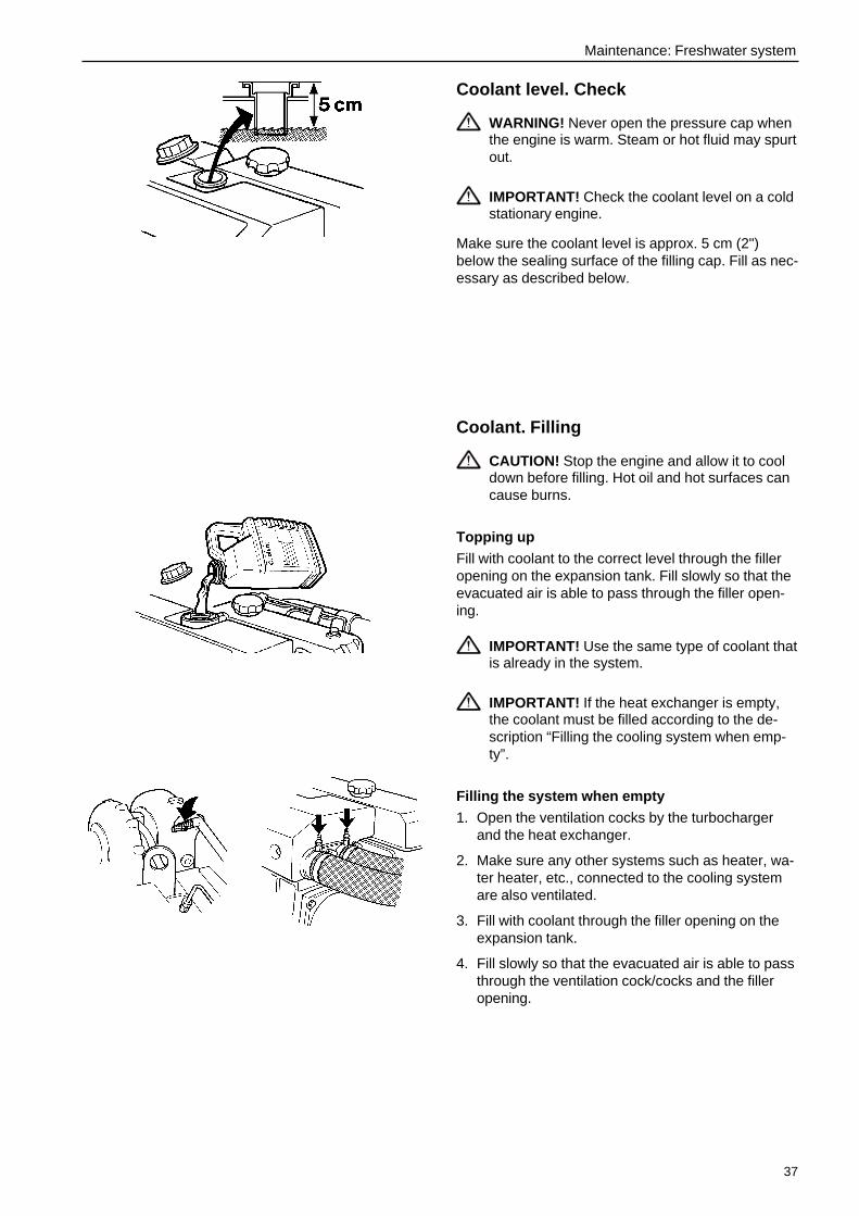
Coolant level. Check
WARNING! Never open the pressure cap whenthe engine is warm. Steam or hot fluid may spurtout.
IMPORTANT! Check the coolant level on a coldstationary engine.
Make sure the coolant level is approx. 5 cm (2")below the sealing surface of the filling cap. Fill as nec-essary as described below.
Coolant. Filling
CAUTION! Stop the engine and allow it to cooldown before filling. Hot oil and hot surfaces cancause burns.
Topping up
Fill with coolant to the correct level through the filleropening on the expansion tank. Fill slowly so that theevacuated air is able to pass through the filler open-ing.
IMPORTANT! Use the same type of coolant thatis already in the system.
IMPORTANT! If the heat exchanger is empty,the coolant must be filled according to the de-scription “Filling the cooling system when emp-ty”.
Filling the system when empty
1. Open the ventilation cocks by the turbochargerand the heat exchanger.
2. Make sure any other systems such as heater, wa-ter heater, etc., connected to the cooling systemare also ventilated.
3. Fill with coolant through the filler opening on theexpansion tank.
4. Fill slowly so that the evacuated air is able to passthrough the ventilation cock/cocks and the filleropening.
38
Maintenance: Freshwater system
5. When coolant that is free from air flows out, theventilation cocks must be closed.
6. Cease filling when the correct level is attained.
7. Start the engine and run it until it reaches operat-ing temperature.
IMPORTANT! The engine must not be start-ed before the system has been bled andfilled.
8. Stop the engine and allow it to cool down. Checkthe coolant level and top up if needed.
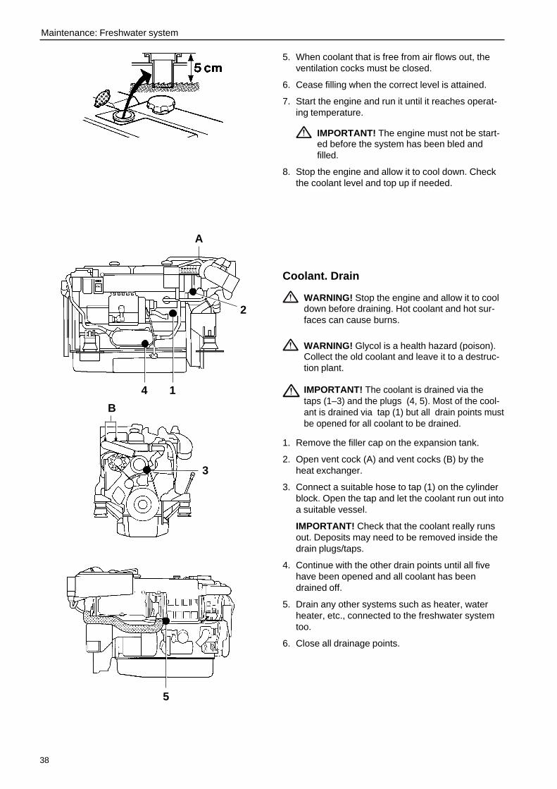
Coolant. Drain
WARNING! Stop the engine and allow it to cooldown before draining. Hot coolant and hot sur-faces can cause burns.
WARNING! Glycol is a health hazard (poison).Collect the old coolant and leave it to a destruc-tion plant.
IMPORTANT! The coolant is drained via thetaps (1–3) and the plugs (4, 5). Most of the cool-ant is drained via tap (1) but all drain points mustbe opened for all coolant to be drained.
1. Remove the filler cap on the expansion tank.
2. Open vent cock (A) and vent cocks (B) by theheat exchanger.
3. Connect a suitable hose to tap (1) on the cylinderblock. Open the tap and let the coolant run out intoa suitable vessel.
IMPORTANT! Check that the coolant really runsout. Deposits may need to be removed inside thedrain plugs/taps.
4. Continue with the other drain points until all fivehave been opened and all coolant has beendrained off.
5. Drain any other systems such as heater, waterheater, etc., connected to the freshwater systemtoo.
6. Close all drainage points.
1
2
4
A
5
3
B
39
Maintenance: Freshwater system
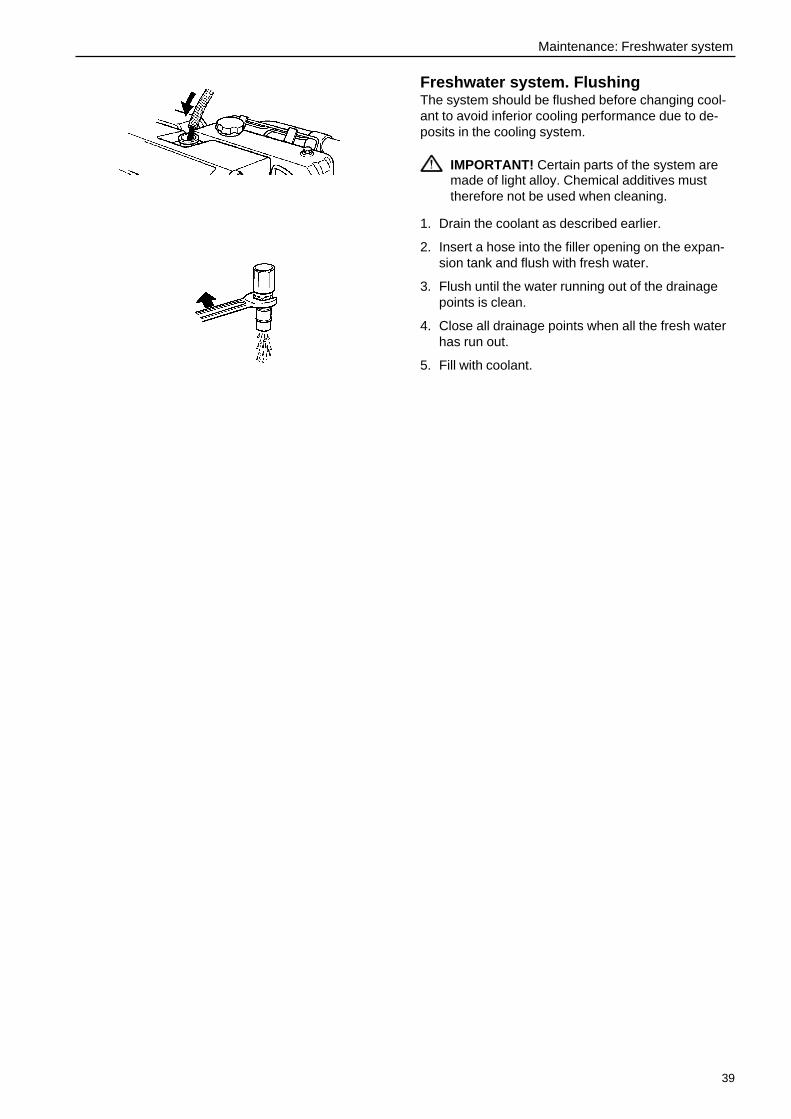
Freshwater system. FlushingThe system should be flushed before changing cool-ant to avoid inferior cooling performance due to de-posits in the cooling system.
IMPORTANT! Certain parts of the system aremade of light alloy. Chemical additives musttherefore not be used when cleaning.
1. Drain the coolant as described earlier.
2. Insert a hose into the filler opening on the expan-sion tank and flush with fresh water.
3. Flush until the water running out of the drainagepoints is clean.
4. Close all drainage points when all the fresh waterhas run out.
5. Fill with coolant.

40
Maintenance: Freshwater system
Cooling system, external cooling
IntroductionA cooling system with external cooling does not have a heat exchanger but is cooled by heat being transferredvia one or two external cooling circuits. A single circuit system serves all the components being cooled. A dualcircuit system has either two freshwater circuits or one freshwater circuit together with one seawater circuit. Inboth cases, one of the circuits cools the engine and the other circuit cools the charge air cooler and the oil cool-ers.
Coolant level. Check
WARNING! Never open the filler cap when theengine is warm. Steam or hot fluid may spurtout.
Make sure the level ends up between the MIN andMAX marks. If there are no marks, the coolant levelshould be approx. 5 cm (2") below the sealing surfaceof the filling cap (1). Fill if necessary with the sametype of coolant that is already in the system.
IMPORTANT! Check the coolant level on a coldstationary engine.
1
Two circuits
Two circuits
One circuit
One or twocircuits
41
Maintenance: Freshwater system
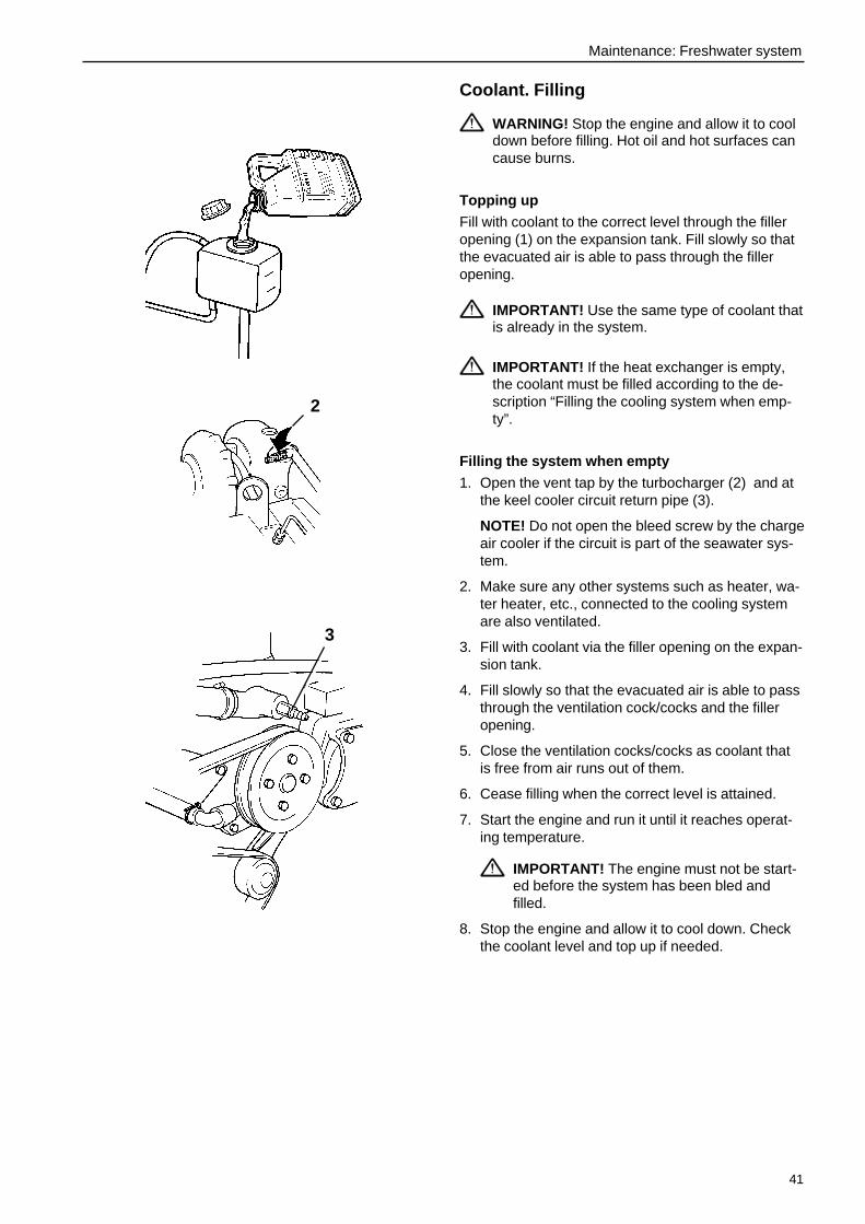
Coolant. Filling
WARNING! Stop the engine and allow it to cooldown before filling. Hot oil and hot surfaces cancause burns.
Topping up
Fill with coolant to the correct level through the filleropening (1) on the expansion tank. Fill slowly so thatthe evacuated air is able to pass through the filleropening.
IMPORTANT! Use the same type of coolant thatis already in the system.
IMPORTANT! If the heat exchanger is empty,the coolant must be filled according to the de-scription “Filling the cooling system when emp-ty”.
Filling the system when empty
1. Open the vent tap by the turbocharger (2) and atthe keel cooler circuit return pipe (3).
NOTE! Do not open the bleed screw by the chargeair cooler if the circuit is part of the seawater sys-tem.
2. Make sure any other systems such as heater, wa-ter heater, etc., connected to the cooling systemare also ventilated.
3. Fill with coolant via the filler opening on the expan-sion tank.
4. Fill slowly so that the evacuated air is able to passthrough the ventilation cock/cocks and the filleropening.
5. Close the ventilation cocks/cocks as coolant thatis free from air runs out of them.
6. Cease filling when the correct level is attained.
7. Start the engine and run it until it reaches operat-ing temperature.
IMPORTANT! The engine must not be start-ed before the system has been bled andfilled.
8. Stop the engine and allow it to cool down. Checkthe coolant level and top up if needed.
3
2
42
Maintenance: Freshwater system
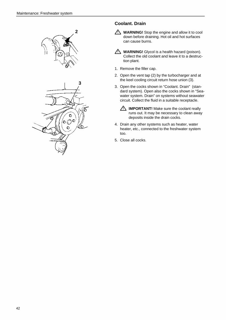
Coolant. Drain
WARNING! Stop the engine and allow it to cooldown before draining. Hot oil and hot surfacescan cause burns.
WARNING! Glycol is a health hazard (poison).Collect the old coolant and leave it to a destruc-tion plant.
1. Remove the filler cap.
2. Open the vent tap (2) by the turbocharger and atthe keel cooling circuit return hose union (3).
3. Open the cocks shown in “Coolant. Drain” (stan-dard system). Open also the cocks shown in “Sea-water system. Drain” on systems without seawatercircuit. Collect the fluid in a suitable receptacle.
IMPORTANT! Make sure the coolant reallyruns out. It may be necessary to clean awaydeposits inside the drain cocks.
4. Drain any other systems such as heater, waterheater, etc., connected to the freshwater systemtoo.
5. Close all cocks.
2
3
43
Maintenance: Seawater system
Seawater system
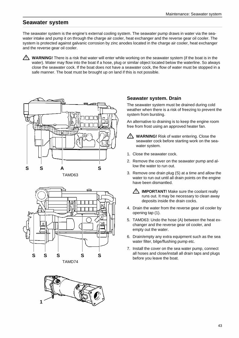
The seawater system is the engine’s external cooling system. The seawater pump draws in water via the sea-water intake and pump it on through the charge air cooler, heat exchanger and the reverse gear oil cooler. Thesystem is protected against galvanic corrosion by zinc anodes located in the charge air cooler, heat exchangerand the reverse gear oil cooler.
WARNING! There is a risk that water will enter while working on the seawater system (if the boat is in thewater). Water may flow into the boat if a hose, plug or similar object located below the waterline. So alwaysclose the seawater cock. If the boat does not have a seawater cock, the flow of water must be stopped in asafe manner. The boat must be brought up on land if this is not possible.
Seawater system. DrainThe seawater system must be drained during coldweather when there is a risk of freezing to prevent thesystem from bursting.
An alternative to draining is to keep the engine roomfree from frost using an approved heater fan.
WARNING! Risk of water entering. Close theseawater cock before starting work on the sea-water system.
1. Close the seawater cock.
2. Remove the cover on the seawater pump and al-low the water to run out.
3. Remove one drain plug (S) at a time and allow thewater to run out until all drain points on the enginehave been dismantled.
IMPORTANT! Make sure the coolant reallyruns out. It may be necessary to clean awaydeposits inside the drain cocks.
4. Drain the water from the reverse gear oil cooler byopening tap (1).
5. TAMD63: Undo the hose (A) between the heat ex-changer and the reverse gear oil cooler, andempty out the water.
6. Drain/empty any extra equipment such as the seawater filter, bilge/flushing pump etc.
7. Install the cover on the sea water pump, connectall hoses and close/install all drain taps and plugsbefore you leave the boat.
TAMD63
S S A S
S S S STAMD74
S
1

44
Maintenance: Seawater system
Impeller. Check/Change
WARNING! Risk of water entering. Close theseawater cock before starting work on the sea-water system.
In some installations, it can be easier to first removethe sea water pump from the engine (see next chap-ter) and then change the impeller.
1. Remove the end cover of the pump. Pull and twistout the impeller with adjustable pliers.
2. Inspect the impeller. Change the impeller if thereare any visible cracks or other defects.
3. Clean the inside of the housing. Lubricate thepump housing and the inside of the cover with awater-resistant grease (that is not aggressive onrubber).
4. Press in the impeller while rotating it (clockwise).
5. Fit the cover with a new gasket.
6. Open the seawater cock.
IMPORTANT! Always carry a spare impellerand gasket.
Sea water pump. Removal and assembly
WARNING! Risk of water entry. Close the seacocks before doing any work on the sea watersystem.
1. Drain the water from the sea water system (pleaserefer to previous page).
2. Undo the coolant pipes to and from the pump andremove the stay (1) on the TAMD74.
3. Remove the pump from the timing housing.
4. Check that the O-ring is undamaged and that it iscorrectly located on the pump.
5. Install the pump, tighten it and install the stay (1)on the TAMD74.
6. Grease the seal rings and install the coolant pipesto and from the pump.
7. TAMD74: Check that seal (2) seals correctlyagainst the charge air cooler.
2
1

45
Maintenance: Seawater system
Zinc anodes. Check/Change
WARNING! Risk of water entering. Close the sea-water cock before starting work on the seawatersystem.
1. Close the seawater cock.
2. Open drain tap (1) on the reverse gear oil coolerand drain off the sea water.
3. Remove the zinc anode in the reverse gear oilcooler (2), in the heat exchanger (3) and in the in-tercooler (4).
NOTE! The sea water in the heat exchanger andintercooler is drained at the same time.
4. Change the anode if less than 50% of its originalsize. Otherwise, clean the anode with emery clothto remove the layer of oxide.
IMPORTANT! Do not use a wire brush orother metal tool for cleaning as this can im-pair the galvanic protection.
5. Fit the zinc anodes. Make sure there is good con-tact between the anode and the metal goods.
6. Close the drain cock (S).
7. Open the seawater cock before starting the en-gine.
8. Make sure there are no leaks.
Seawater filter. Check/CleanThe seawater filter is an accessory and is available intwo models.
If the water the boat is in is severely polluted, con-tains large amounts of seaweed, etc., the filter mustbe checked more often than is specified in the main-tenance schedule. The filter can otherwise becomeclogged and the engine overheat.
WARNING! Risk of water entering. Close theseawater cock before starting work on the sea-water system.
1. Close the seawater cock.
2. Remove the cover (1) and lift up the insert.
3. Clean the insert and the housing (2).
4. Assemble the parts as illustrated below. Inspectgaskets and O-ring. Change if necessary.
5. Open the seawater valve and check for leaks.
3
1
2
4

46
Maintenance: Seawater system
Charge air cooler. Check the drain holeCondensation can form in the charge air cooler duringoperation. The condensation can be drained from anipple (1) on the bottom of the charge air cooler.Make sure the nipple is not blocked.
IMPORTANT ! If considerable amounts of waterrun out of the drain hole, the insert must be re-moved and test pressurized. This must be doneby an authorised workshop.

47
Maintenance: Fuel system
Fuel system
Use only fuel recommended in the fuel specifications below. Always observe cleanliness when refuelling andworking with the fuel system.
All work concerning the engine injection pump or injectors is to be carried out at an authorised workshop. Break-ing the seal on the injection pump will void the warranty.
WARNING! Fire hazard. Work performed on the fuel system must be done on a cold engine. Fuel spill onhot surfaces or electrical components can cause fires. Keep fuel-drenched rags where they are safe in caseof fire.
Fuel specificationFuel must comply with national and international stan-dards at the least, e.g.:
EN590 (with national environment and cold require-ments)
ASTM-D975-No 1-D, 2-D
JIS KK 2204
Sulphur content
Complying with legal requirements in each country. Ifthe sulphur content exceeds 0.5 wt%, service inter-vals must be changed, see “Maintenance: Lubricatingsystem”.
Fuels with low density (city diesel) can result in a lossof power by approx. 5% and an increase in fuel con-sumption of approx. 2–3 %.
Fuel delivery pipesThe delivery pipes must not be bent, twisted or ex-erted to any other forces. Change delivery pipes thatare damaged.
WARNING! Fire hazard! The fuel delivery pipesmust not be bent, twisted or exerted to any otherforces.

48
Maintenance: Fuel system
Fuel filters. ChangeClean the filter bracket and place a receptacle underthe filters.
NOTE! Leave the old filters to a destruction plant.
Standard fuel filters1. Unscrew the filters.
2. Make sure the new filters are absolutely clean andthat the gaskets are free from faults. Apply a littleoil to the gaskets.
3. Screw on the filters by hand until they make con-tact with the sealing surface. Then screw a furtherhalf turn, not any more!
4. Bleed the fuel system as described above.
5. Start the engine and check for leaks.
Fuel system. BleedingThe fuel system must be bled e.g. after changing fuelfilter, if the fuel tank has been run dry and after longstops. Refer to the next page for bleeding when re-placing a switchable fuel filter during operation.
1. Place a receptacle under the fuel filter and openthe bleed screw (1) on the filter bracket.
2. Pump fuel using the hand pump (2) until the fuelrunning out is free from air bubbles. Tighten thebleed screw while fuel is running out.
3. Pump another 10–20 times with the bleed screwclosed to attain a good feed pressure.
4. Make sure there are no leaks.
No other bleeding is normally required but if the en-gine will not start, the injection pump must be bled asfollows:
1. Detach the connection (3) and pump with the handpump until the fuel running out is free from air.
2. Tighten the conection while fuel is running out.
3. Pump another 10–20 times to attain a good feedpressure.

49
Maintenance: Fuel system
Switchable type fuel filtersSwitchable fuel filters can be changed while runningas the flow of fuel can be cut off to one filter at a time.
WARNING! Working on or approaching a run-ning engine is a safety hazard. Beware of rotat-ing parts and hot surfaces.
1. Put the lever (2) in its right-hand end position.
2. Unscrew the left-hand fuel filter. Use a filterwrench if necessary.
3. Screw on the filters by hand until they make con-tact with the sealing surface. Then screw a furtherhalf turn, not any more!
4. Open the left-hand bleed screw (1) on the filterbracket. Put the lever in operating position(straight up). Close the bleed screw when the fuelrunning out is free from air.
5. Put the lever in its left-hand end position andchange the right-hand fuel filter in the same way.
Fuel pre-filter. Check
WARNING! Working on or approaching a run-ning engine is a safety hazard. Beware of rotat-ing parts and hot surfaces.
The fuel pre-filter/water separator are accessoriesand available as single or dual models.
The dual filter is equipped with a pressure gauge (1)indicating when it is time to change the filter insert.
The filter inserts must be changed according to themaintenance schedule recommendations or ealier ifthe pressure gauge indicates a vacuum of 6–10 in.Hg at idling speed or 16–20 in. Hg at full enginespeed/load.
1

50
Maintenance: Fuel system
Fuel pre-filter. DrainagePlace a receptacle under the filter. Drain off waterand contaminants through the plug (1) in the bottomof the glass bowl.
IMPORTANT! Do not drain until a few hours af-ter stopping.
Fuel pre-filter. Change filter elementsThe fuel pre-filter/water separator are accessoriesand available as single or dual models.
The dual filter inserts can be changed while runningas the flow of fuel can be cut off to one filter containerat a time.
The flow of fuel is governed by putting the knob (1) inthe following positions:
A: Normal running (both filters connected).
B: Left filter insert can be changed.
C: Right filter insert can be changed.
D: Both filters turned off.
1
A
D
BC
1

51
Maintenance: Fuel system
Change filter elements:
Close the fuel cocks on the tank or cut off the flow offuel with the knob (1) for the filter insert to change ifrunning.
WARNING! Working on or approaching a run-ning engine is a safety hazard. Beware of rotat-ing parts and hot surfaces.
1. Place a receptacle under the filter.
2. Undo the T-bolt (2) and remove the cover (3).
3. Take out the insert carefully while turning it.
4. Drain off water and contaminants through thedrain plug (4).
5. Fit a new filter insert and fill the container withclean fuel.
IMPORTANT! Cleanliness! No contami-nants must be allowed in the fuel system.
6. Change the gasket on the cover and the O-ringon the T-bolt. Moisten the gasket and O-ring withfuel before assembling.
7. Fit the cover and tighten it by hand.
8. Wipe off any fuel from the heat shield.
9. Dual filter: Change the other filter insert in thesame way.
10. Open the fuel cocks and put the knob (1) in posi-tion for normal running. Make sure there are noleaks.
1
4
3
2
4
3
2

52
Maintenance: Electrical system
Electrical system
The engines are equipped with a bi-polar electrical system with alternating current generator. System voltage is12 alternativly 24V.
WARNING! Before starting work on the electrical system, the engine must be stopped and the poweredturned off with the main switch/switches. Shore power to the engine heater, battery charger or other extraequipment fitted on the engine must be disconnected.
Main switchesThe main switches must never be turned off until theengine has been stopped. Breaking the circuit be-tween the alternator and the batteries while the en-gine is running can damage the alternator. For thesame reason, the charge circuits must never beswitched while the engine is running.
IMPORTANT! Never turn the power off usingthe main switches while the engine is running.
Electrical connectionsMake sure electrical connections are tightened, dryand free from oxide. If necessary, spray these con-nections with water-repellant (Volvo Penta all-roundoil).
FusesTwo semi-automatic 8A fuses are located in the mainelectric terminal box. Fuses cut the current whenthere is an overload and are reset by pressing thebuttons on the side of the main electrical terminalbox. Determine the cause of the overload before re-setting the fuses.

53
Maintenance: Electrical system
Battery. Maintenance
WARNING! Risk for fire and explosion. Neverexpose the battery to naked flames or sparks.
WARNING! Never reverse the polarity of thebattery. Risk of sparks and explosion.
WARNING! Battery electrolyte is extremely cor-rosive. Protect eyes, skin and clothes whenhandling batteries. Always use protectivegoggles and gloves. In case of splashes on theskin, wash with soap and plenty of water. Incase of splashes in the eyes, rinse immediatelywith plenty of water and call a doctor.
Connecting and disconnecting
Connect the (+) cable (red) to the (+) terminal of thebattery first. Then connect the (–) cable (black) to the(–) pole of the battery.
Disconnect the (–) cable (black) first and then the (+)cable (red).
Cleaning
Keep batteries dry and clean. Contaminants and ox-ide on batteries and battery terminals can causeshort-circuits, voltage drops and discharging, espe-cially in damp weather. Clean oxide from battery ter-minals and cable shoes with a brass brush. Tightencable shoes well and grease them with terminalgrease or petroleum jelly.
Electrolyte level
The electrolyte should be 5–10 mm (0.2–0.4") abovethe cell plates in the battery. If necessary, top up withdistilled water. The battery should be charged for atleast 30 minutes after filling by running the engine atidling speed.
NOTE! Special instructions must be followed for cer-tain maintenance-free batteries.
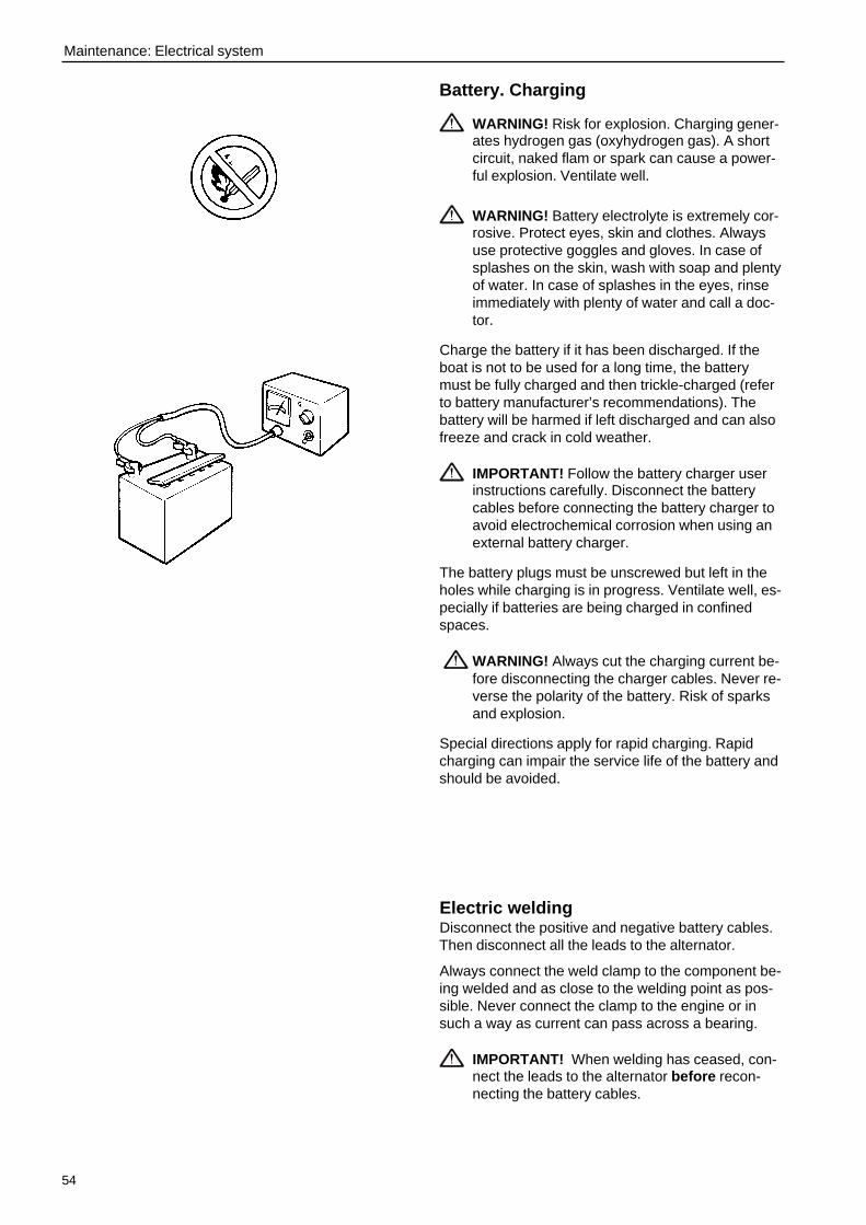
54
Maintenance: Electrical system
Battery. Charging
WARNING! Risk for explosion. Charging gener-ates hydrogen gas (oxyhydrogen gas). A shortcircuit, naked flam or spark can cause a power-ful explosion. Ventilate well.
WARNING! Battery electrolyte is extremely cor-rosive. Protect eyes, skin and clothes. Alwaysuse protective goggles and gloves. In case ofsplashes on the skin, wash with soap and plentyof water. In case of splashes in the eyes, rinseimmediately with plenty of water and call a doc-tor.
Charge the battery if it has been discharged. If theboat is not to be used for a long time, the batterymust be fully charged and then trickle-charged (referto battery manufacturer’s recommendations). Thebattery will be harmed if left discharged and can alsofreeze and crack in cold weather.
IMPORTANT! Follow the battery charger userinstructions carefully. Disconnect the batterycables before connecting the battery charger toavoid electrochemical corrosion when using anexternal battery charger.
The battery plugs must be unscrewed but left in theholes while charging is in progress. Ventilate well, es-pecially if batteries are being charged in confinedspaces.
WARNING! Always cut the charging current be-fore disconnecting the charger cables. Never re-verse the polarity of the battery. Risk of sparksand explosion.
Special directions apply for rapid charging. Rapidcharging can impair the service life of the battery andshould be avoided.
Electric weldingDisconnect the positive and negative battery cables.Then disconnect all the leads to the alternator.
Always connect the weld clamp to the component be-ing welded and as close to the welding point as pos-sible. Never connect the clamp to the engine or insuch a way as current can pass across a bearing.
IMPORTANT! When welding has ceased, con-nect the leads to the alternator before recon-necting the battery cables.
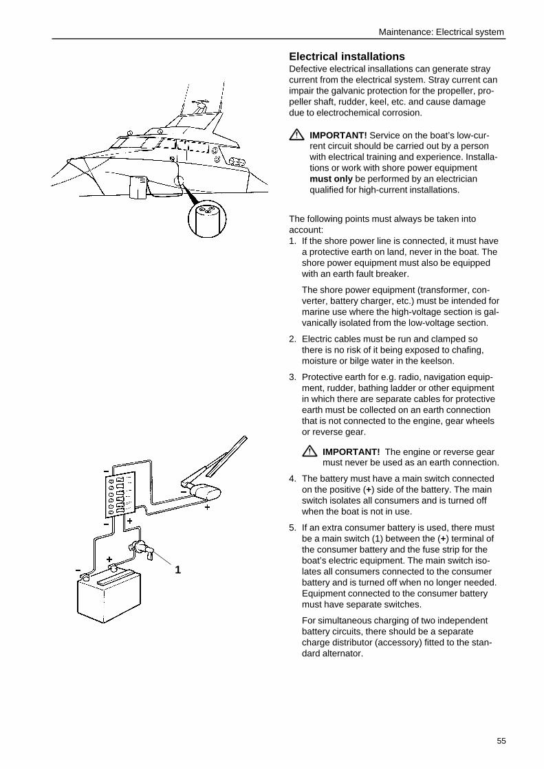
55
Maintenance: Electrical system
Electrical installationsDefective electrical insallations can generate straycurrent from the electrical system. Stray current canimpair the galvanic protection for the propeller, pro-peller shaft, rudder, keel, etc. and cause damagedue to electrochemical corrosion.
IMPORTANT! Service on the boat’s low-cur-rent circuit should be carried out by a personwith electrical training and experience. Installa-tions or work with shore power equipmentmust only be performed by an electricianqualified for high-current installations.
The following points must always be taken intoaccount:1. If the shore power line is connected, it must have
a protective earth on land, never in the boat. Theshore power equipment must also be equippedwith an earth fault breaker.
The shore power equipment (transformer, con-verter, battery charger, etc.) must be intended formarine use where the high-voltage section is gal-vanically isolated from the low-voltage section.
2. Electric cables must be run and clamped sothere is no risk of it being exposed to chafing,moisture or bilge water in the keelson.
3. Protective earth for e.g. radio, navigation equip-ment, rudder, bathing ladder or other equipmentin which there are separate cables for protectiveearth must be collected on an earth connectionthat is not connected to the engine, gear wheelsor reverse gear.
IMPORTANT! The engine or reverse gearmust never be used as an earth connection.
4. The battery must have a main switch connectedon the positive (+) side of the battery. The mainswitch isolates all consumers and is turned offwhen the boat is not in use.
5. If an extra consumer battery is used, there mustbe a main switch (1) between the (+) terminal ofthe consumer battery and the fuse strip for theboat’s electric equipment. The main switch iso-lates all consumers connected to the consumerbattery and is turned off when no longer needed.Equipment connected to the consumer batterymust have separate switches.
For simultaneous charging of two independentbattery circuits, there should be a separatecharge distributor (accessory) fitted to the stan-dard alternator.
1
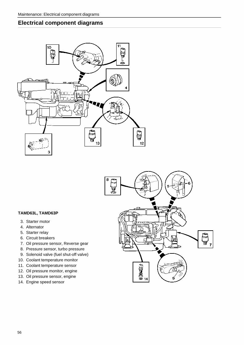
56
Maintenance: Electrical component diagrams
Electrical component diagrams
TAMD63L, TAMD63P
3. Starter motor4. Alternator5. Starter relay6. Circuit breakers7. Oil pressure sensor, Reverse gear8. Pressure sensor, turbo pressure9. Solenoid valve (fuel shut-off valve)
10. Coolant temperature monitor11. Coolant temperature sensor12. Oil pressure monitor, engine13. Oil pressure sensor, engine14. Engine speed sensor
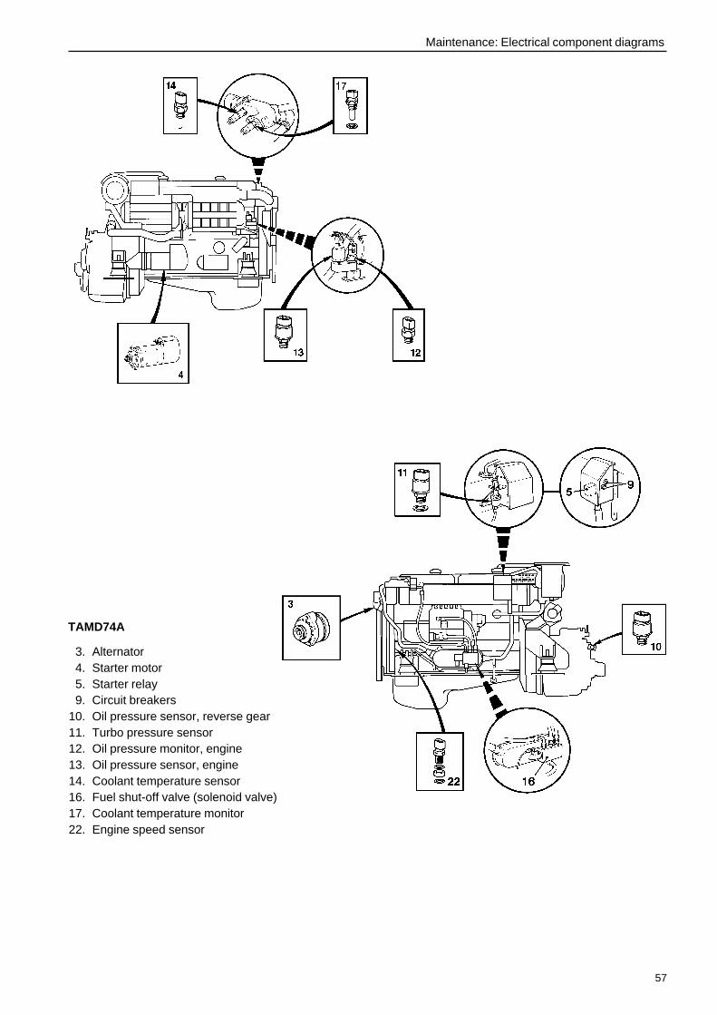
57
Maintenance: Electrical component diagrams
TAMD74A
3. Alternator4. Starter motor5. Starter relay9. Circuit breakers
10. Oil pressure sensor, reverse gear11. Turbo pressure sensor12. Oil pressure monitor, engine13. Oil pressure sensor, engine14. Coolant temperature sensor16. Fuel shut-off valve (solenoid valve)17. Coolant temperature monitor22. Engine speed sensor

58
Maintenance: Reverse gear
Reverse gear
Oil level. Check and filling
CheckThe oil level should be checked once the reversegear has attained operating temperature with the en-gine idling and the controls in neutral.
WARNING! Working on or approaching a run-ning engine is a safety hazard. Beware of rotat-ing parts and hot surfaces.
Pull out the dipstick, wipe it off and insert it back intothe reverse gear. Pull out the dipstick again andcheck the oil level. The correct oil level is between theMAX and MIN marks.
FillingIf necessary, top up with oil in the filler opening on topof the reverse gear. Oil grades and capacity: SeeTechnical Data.
IMPORTANT! Never overfill the reverse gear.The oil level must always lie within the recom-mended levels.
Oil strainer. Cleaning
WARNING! Working on or approaching a run-ning engine is a safety hazard. Beware of rotat-ing parts and hot surfaces.
1. Remove the plug/screw and carefully take out thefilter (1) from the filter housing.
IMPORTANT! Always observe the greatestcleanliness. Dirt must not enter the filterhousing.
2. Clean the filter and other parts with paraffin.
3. Carefully refit all the parts.
4. Tighten the plug/screw.
5. Start the engine and check for leaks.
Twin Disc
1
ZF (MPM)
1
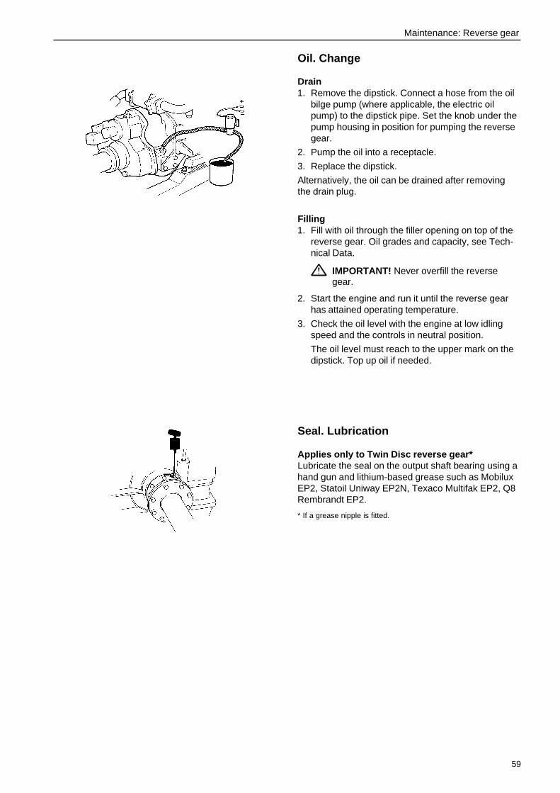
59
Maintenance: Reverse gear
Oil. Change
Drain1. Remove the dipstick. Connect a hose from the oil
bilge pump (where applicable, the electric oilpump) to the dipstick pipe. Set the knob under thepump housing in position for pumping the reversegear.
2. Pump the oil into a receptacle.
3. Replace the dipstick.
Alternatively, the oil can be drained after removingthe drain plug.
Filling1. Fill with oil through the filler opening on top of the
reverse gear. Oil grades and capacity, see Tech-nical Data.
IMPORTANT! Never overfill the reversegear.
2. Start the engine and run it until the reverse gearhas attained operating temperature.
3. Check the oil level with the engine at low idlingspeed and the controls in neutral position.
The oil level must reach to the upper mark on thedipstick. Top up oil if needed.
Seal. Lubrication
Applies only to Twin Disc reverse gear*Lubricate the seal on the output shaft bearing using ahand gun and lithium-based grease such as MobiluxEP2, Statoil Uniway EP2N, Texaco Multifak EP2, Q8Rembrandt EP2.
* If a grease nipple is fitted.
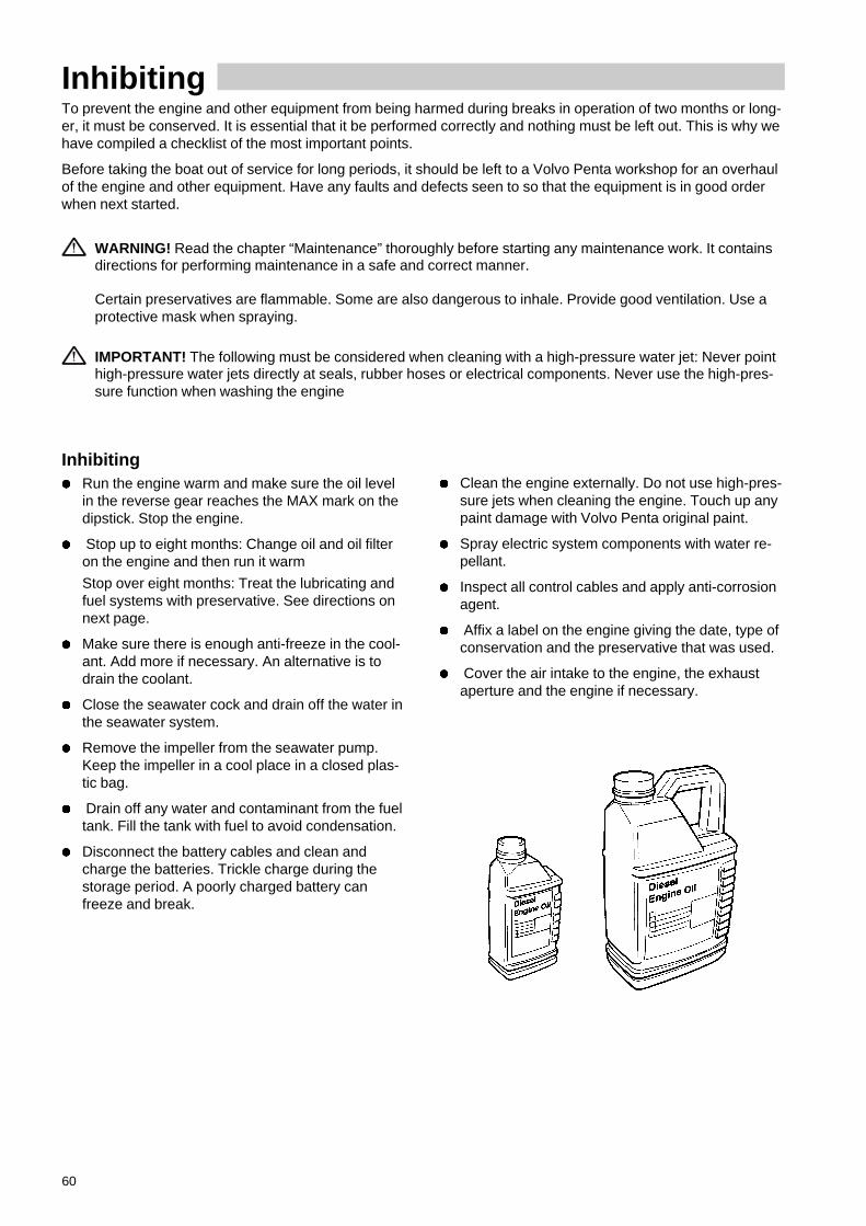
60
InhibitingTo prevent the engine and other equipment from being harmed during breaks in operation of two months or long-er, it must be conserved. It is essential that it be performed correctly and nothing must be left out. This is why wehave compiled a checklist of the most important points.
Before taking the boat out of service for long periods, it should be left to a Volvo Penta workshop for an overhaulof the engine and other equipment. Have any faults and defects seen to so that the equipment is in good orderwhen next started.
WARNING! Read the chapter “Maintenance” thoroughly before starting any maintenance work. It containsdirections for performing maintenance in a safe and correct manner.
Certain preservatives are flammable. Some are also dangerous to inhale. Provide good ventilation. Use aprotective mask when spraying.
IMPORTANT! The following must be considered when cleaning with a high-pressure water jet: Never pointhigh-pressure water jets directly at seals, rubber hoses or electrical components. Never use the high-pres-sure function when washing the engine
Inhibitingl Run the engine warm and make sure the oil level
in the reverse gear reaches the MAX mark on thedipstick. Stop the engine.
l Stop up to eight months: Change oil and oil filteron the engine and then run it warm
Stop over eight months: Treat the lubricating andfuel systems with preservative. See directions onnext page.
l Make sure there is enough anti-freeze in the cool-ant. Add more if necessary. An alternative is todrain the coolant.
l Close the seawater cock and drain off the water inthe seawater system.
l Remove the impeller from the seawater pump.Keep the impeller in a cool place in a closed plas-tic bag.
l Drain off any water and contaminant from the fueltank. Fill the tank with fuel to avoid condensation.
l Disconnect the battery cables and clean andcharge the batteries. Trickle charge during thestorage period. A poorly charged battery canfreeze and break.
l Clean the engine externally. Do not use high-pres-sure jets when cleaning the engine. Touch up anypaint damage with Volvo Penta original paint.
l Spray electric system components with water re-pellant.
l Inspect all control cables and apply anti-corrosionagent.
l Affix a label on the engine giving the date, type ofconservation and the preservative that was used.
l Cover the air intake to the engine, the exhaustaperture and the engine if necessary.

61
Inhibiting
Taking out of storagel Remove any protection on the engine, air intake
and exhaust pipe.
l Top up with lubricant of the correct grade in theengine if necessary. Fit a new oil filter if this wasnot done during conservation.
l Make sure there is oil in the reverse gear.
l Fit a new fuel filter and bleed the fuel system.
l Check drive belts.
l Check the condition of rubber hoses and checkthe tightness of all hose clips.
l Close the drain cocks and fit the drain plugs.
l Fit the impeller in the seawater pump.
l Check the coolant level and anti-freeze. Top up asnecessary.
l Connect the fully charged batteries.
l Open the seawater cock.
l Start the engine (if the boat is in the water) andrun the engine warm at idling speed before loadingit.
l Check for oil, fuel or coolant leaks.
l Check the oil level in the reverse gear. Top up ifnecessary.
Conserving the lubricating and fuel systems for stops longer than eightmonths:
l Drain the oil from the engine and fill with pre-servative* to just over the MIN mark on the dip-stick.
l Connect suction (1) and return fuel lines (2) to afuel can filled with 1/3 preservative* and 2/3diesel fuel.
l Bleed the fuel system.
l Start the engine and run it at fast idling speeduntil approximately two litres of fuel have beenconsumed. Stop the engine and connect thenormal fuel lines.
l Empty the preservative from the engine.
l Follow the directions on the previous page inother respects.
* Preservatives are available from oil companies.
1
2

62
TroubleshootingA number of symptoms and possible causes for engine disturbances are described in the table below. If faults orhitches arise that you cannot solve alone, you must always get in touch with your Volvo Penta dealer.
WARNING! Read the safety directions for maintenance and service in the chapter “Safety information” be-fore starting work.
Symptom and possible cause
Engine can not be stopped 1, 2, 3, 5
Starter motor does not rotate 1, 2, 3, 4, 5
Starter motor rotates slowly 1, 2
Engine does not start 6, 7, 8, 9
Engine starts but stops again 7, 8 , 9, 13
Engine is difficult to start 7, 8 , 9, 13
Engine does not reach correct operating speed at full throttle 7, 8, 9, 10, 11, 12, 13, 18
Engine knocks 14
Engine run unevenly 7, 8, 9, 13, 14
Engine vibrates 18, 19
High fuel consumption 10, 11, 13, 15
Black exhaust smoke 13, 15, 18
Blue or white exhaust smoke 14, 15, 26
Oil pressure too low 16, 17
Coolant temperature too high 20, 21, 22, 23, 24, 25, 26
No charge, or poor charge 2, 27
1. Flat batteries2. Poor contact/broken electrical
cable3. Main switch turned off4. Engine control not in neutral5. A fuse/circuit breaker has tripped6. Lack of fuel7. Blocked fuel filter/supply pump8. Air in fuel system9. Water/contamination in fuel
10. Boat abnormally loaded11. Fouled hull/propeller12. Engine speed control wrongly
adjusted13. Insufficient air supply14. Too high coolant temperature15. Too low coolant temperature16. Too low lubrication oil level17. Blocked oil filter18. Defective/wrong propeller
19. Faulty engine mounting20. Not enough coolant21. Air in fresh water system22. Blocked sea water inlet/pipe/filter23. Circulation pump drive belt slips24. Defective impeller25. Defective/wrong thermostat26. Too high lubrication oil level27. Alternator drive belt slips
63
Troubleshooting
Start using auxiliary batteries
WARNING! Ventilate well. Batteries generateoxyhydrogen gas, which is extremely flammableand explosive. A short circuit, naked flame orspark can cause a powerful explosion.
Never reverse the polarity of the battery. Risk ofsparks and explosion.
1. Make sure the rated voltage of the auxiliary bat-tery is the same as the system voltage of the en-gine.
2. Connect the red auxiliary cable to the dischargedbattery’s + terminal and then to the auxiliary bat-tery’s + terminal .
3. Connect the black auxiliary cable to the auxiliarybattery’s – terminal and ultimately to a placeaway from the discharged batteries, e.g. on themain switch negative lead or the negative leadconnection on the starter motor.
WARNING! The black auxiliary cable (–)must not come in contact with the positiveconnection on the starter motor.
4. Start the engine and run at fast idling speed forabout ten minutes to charge the batteries.
WARNING! Working on or approaching arunning engine is a safety hazard. Beware ofrotating parts and hot surfaces.
Do not touch the connections while attempt-ing to start: Risk of sparks. Do not bend overthe batteries either.
5. Stop the engine. Remove the auxiliary cables inthe exact reverse order to connecting.
64
Technical DataGeneralEngine designation TAMD63L-A TAMD74A-A
TAMD63L-B TAMD74A-BTAMD63P-A
Number of cylinders .................................................. 6 6Displacement ............................................................ 5.48 dm3 (334 in3) 7.28 dm3 (444 in3)Low idling speed ....................................................... 600 ±20 rpm 600 ±30 rpmValve clearance,
inlet* ....................................................................... 0.50 mm (0.0197") 0.50 mm (0.0197")outlet* ..................................................................... 0.65 mm (0.0256") 0.65 mm (0.0256")
Compression pressure** ........................................... 2.2 MPa (319 psi) 2.2 MPa (319 psi)Weight*** ................................................................... 745 kg (1642 lbs) 860 kg (1896 lbs)
* Applies to cold or warm engine (stopped).** At starter motor speed (300 rpm).
*** With heat exchanger, without reverse gear or clutch.
Lubricating systemOil capacity, without oil filters*,No engine inclination ................................................. 20 liters (5.3 US gals) 24 liters (6.3 US gals)
volume difference min.–max. ................................ 7 liters (1.8 US gals) 7 liters (1.8 US gals)Engine inclination 5° ................................................. 16 liters (4.2 US gals) 20 liters (5.3 US gals)
volume difference min.–max. ................................ 6 liters (1.6 US gals) 5 liters (1.3 US gals)Engine inclination 10° ............................................... 12 liters (3.23 US gals) 14 liters (3.7 US gals)
volume difference min.–max. ................................ 5 liters (1.3 US gals) 4 liters (1.1 US gals)Oil pressure at operating speed ................................ 300–550 kPa (43.5–79.8 psi) 450–650 kPa (65.3–94 psi)Oil pressure at idling speed ...................................... 150 kPa (21.8 psi) 150 kPa (21.8 psi)
* Note. Engine oil filter and by-pass filter have each acapacity of approx. 0.5 liter (0.5 quart).
Fuel systemEngine designation TAMD63L-A TAMD74A-A
TAMD63L-B
Injection pump, setting .............................................. 16° ±0.5° BTDC. 15° ±0.5° BTDC.
Engine designation TAMD63P-A TAMD74A-B
Injection pump, setting .............................................. 15° ±0.5° BTDC. 12° ±0.5° BTDC.
Cooling systemCapacity .................................................................... 27 liters (7.1 US gals) 34 liters (9.0 US gals)

65
Technical Data
Reverse gear
ZF (MPM)Type designation IRM 220A-1 IRM 220PL-E IRM 220V-LD
Oil capacity, approx .................................................. 4.0 liters 5.3 liters 5.5 liters(1.06 US gals) (1.40 US gals) (1.45 US gals)
Oil grade (to API system) .......................................... CC, CD, CE CC, CD, CE CC, CD, CEViscosity .................................................................... SAE30* SAE30* SAE30*
alt. in tropical regions ................................ SAE40* SAE40* SAE40*Working oil pressure ................................................. 2.0–2.2 MPa 2.5 MPa 2.3–2.4 MPa
(290–319 psi) (363 psi) (334–348 psi)Weight, approx .......................................................... 53 kg 70 kg 86 kg
(117 lbs) (154 lbs) (190 lbs)
Twin DiscType designation MG 5061A MG 5062V MG5075SC
Oil capacity, approx .................................................. 3.2 liters 5.6 liters 5.9 liters(0.85 US gals) (1.48 US gals) (1.6 US gals)
Oil grade (to API system) .......................................... CC, CD, CE CC, CD, CE CC, CD, CEViscosity .................................................................... SAE30* SAE30* SAE40*
alt. in tropical regions ................................ SAE40* SAE40*Oil pressure at oil temperature 82°C (180°F),
engaged, 1800 rpm ................................................ 2.3 MPa 2.05–2.2 MPa 2.28 MPa(334 psi) (297–319 psi) (331 psi)
at cruising speed, min. ........................................... 2.07 MPa 1.9 MPa(300 psi) (276 psi)
Weight, approx. ......................................................... 113 kg 142 kg 140 kg(249 lbs) (313 lbs) (309 lbs)
Type designation MG5091SC MG5091DC
Oil capacity, approx. ................................................. 9 liters 18 liters(2.38 US gals) (4.75 US gals)
Oil grade (to API system) .......................................... CC, CD, CE CC, CD, CEViscosity .................................................................... SAE30* SAE30*
alt. in tropical regions .................................. SAE40* SAE40*Working oil pressure ** “Neutral” ............................... 0.207–0.634 MPa (30–92 psi)Working oil pressure ** “Forward” ............................. 1.57–1.63 MPa (228–236 psi)Weight, approx. ......................................................... 220 kg 250 kg
(485 lbs) (550 lbs)
* Note! Only single-grade lubricating oil (only one viscositynumber) may be used in the reverse gear.
** At oil temperature 82°C (180°F) and 1800 rpm.
Electrical systemEngine designation TAMD63L-A TAMD74A-A
TAMD63L-B TAMD74A-BTAMD63P-A
System voltage ......................................................... 12V (or 24V) 24V (or 12V)Battery capacity,
12V system ............................................................ 2 pcs. coupled parallel 12V, max. 110 Ah/battery24V system ............................................................ 2 pcs. coupled in series 12V, max. 143 Ah

66
Notes
...........................................................................................................................................................................................
...........................................................................................................................................................................................
...........................................................................................................................................................................................
...........................................................................................................................................................................................
...........................................................................................................................................................................................
...........................................................................................................................................................................................
...........................................................................................................................................................................................
...........................................................................................................................................................................................
...........................................................................................................................................................................................
...........................................................................................................................................................................................
...........................................................................................................................................................................................
...........................................................................................................................................................................................
...........................................................................................................................................................................................
...........................................................................................................................................................................................
...........................................................................................................................................................................................
...........................................................................................................................................................................................
...........................................................................................................................................................................................
...........................................................................................................................................................................................
...........................................................................................................................................................................................
...........................................................................................................................................................................................
...........................................................................................................................................................................................
...........................................................................................................................................................................................
...........................................................................................................................................................................................
...........................................................................................................................................................................................
...........................................................................................................................................................................................
...........................................................................................................................................................................................

67
Notes
...........................................................................................................................................................................................
...........................................................................................................................................................................................
...........................................................................................................................................................................................
...........................................................................................................................................................................................
...........................................................................................................................................................................................
...........................................................................................................................................................................................
...........................................................................................................................................................................................
...........................................................................................................................................................................................
...........................................................................................................................................................................................
...........................................................................................................................................................................................
...........................................................................................................................................................................................
...........................................................................................................................................................................................
...........................................................................................................................................................................................
...........................................................................................................................................................................................
...........................................................................................................................................................................................
...........................................................................................................................................................................................
...........................................................................................................................................................................................
...........................................................................................................................................................................................
...........................................................................................................................................................................................
...........................................................................................................................................................................................
...........................................................................................................................................................................................
...........................................................................................................................................................................................
...........................................................................................................................................................................................
...........................................................................................................................................................................................
...........................................................................................................................................................................................
...........................................................................................................................................................................................

68
Notes
...........................................................................................................................................................................................
...........................................................................................................................................................................................
...........................................................................................................................................................................................
...........................................................................................................................................................................................
...........................................................................................................................................................................................
...........................................................................................................................................................................................
...........................................................................................................................................................................................
...........................................................................................................................................................................................
...........................................................................................................................................................................................
...........................................................................................................................................................................................
...........................................................................................................................................................................................
...........................................................................................................................................................................................
...........................................................................................................................................................................................
...........................................................................................................................................................................................
...........................................................................................................................................................................................
...........................................................................................................................................................................................
...........................................................................................................................................................................................
...........................................................................................................................................................................................
...........................................................................................................................................................................................
...........................................................................................................................................................................................
...........................................................................................................................................................................................
...........................................................................................................................................................................................
...........................................................................................................................................................................................
...........................................................................................................................................................................................
...........................................................................................................................................................................................
...........................................................................................................................................................................................

NB! This offer is valid for a period of 12 months from delivery of the boat.Availability after this period will be as far as supplies admit.
Post or fax this coupon to:Document & Distribution CenterOrder DepartmentARU2, Dept. 64620SE-405 08 GöteborgSwedenFax: +46 31 545 772
Orders can also be placed viathe Internet:http://www.volvopenta.com/manual/coupon
Yes please,I would like an operator’s manual in English at no charge.
Publication number: 7740714-6
Name
Address
Country 4220
0/61
5001
/155
0999
0019
2
"
Bitte beachten Sie, dass dieses Angebot für die Dauer von 12 Monaten ab demLieferdatum des Bootes gilt, danach bis zum Aufbrauchen des Lagerbestandes.
Schicken Sie den Couponper Post oder als Fax an:Document & Distribution CenterOrder DepartmentARU2, Dept. 64620SE-405 08 GöteborgSchwedenFax: +46 31 545 772
Die Bestellung kann auch überdas Internet erfolgen:http://www.volvopenta.com/manual/coupon
Ja,ich will kostenlos eine Betriebsanleitung in deutscher Sprache erhalten.
Publikationsnummer: 7740715-3
Name
Anschrift
Land 4220
0/61
5001
/155
0999
0019
2
"
Notez que l’offre est valable pendant 12 mois à partir de la date de livrai-son du bateau, ensuite seulement en fonction des stocks disponibles.
Envoyez ou faxez le bon decommande à:Document & Distribution CenterOrder DepartmentARU2, Dept. 64620SE-405 08 GöteborgSuèdeFax: +46 31 545 772
Vous pouvez également pas-ser la commande par Internet:http://www.volvopenta.com/manual/coupon
Oui merci,Je souhaite recevoir un manuel d’instructions gratuit en français.Numéro de publication: 7740716-1
Nom
Adresse
Pays 4220
0/61
5001
/155
0999
0019
2
"

Si ricorda che l’offerta è valida per 12 mesi dalla data di consegna dell’imbarcazio-ne; dopo il suddetto periodo l’offerta resta valida solo in base alla disposizione dellapubblicazione in oggetto.
Spedire il tagliando per postao per fax a:Document & Distribution CenterOrder DepartmentARU2, Dept. 64620SE-405 08 GöteborgSveziaFax: +46 31 545 772
L’ordinazione può essere fattaanche su Internet:http://www.volvopenta.com/manual/coupon
Sì, grazie,desidero ricevere gratuitamente un manuale d’istruzioni in lingua italiana.
Public. No.: 7740718-7
Nome e Cognome
Indirizzo
Paese 4220
0/61
5001
/155
0999
0019
2
"
Nótese que el ofrecimiento vale durante 12 meses después de la fecha de entregade la embarcación, y posteriormente solamente mientras duren las existencias.
Franquear o enviar fax a:Document & Distribution CenterOrder DepartmentARU2, Dept. 64620SE-405 08 GöteborgSueciaFax: +46 31 545 772
El pedido puede hacerse tam-bién por internet:http://www.volvopenta.com/manual/coupon
Sí gracias,deseo recibir gratuitamente un libro de instrucciones en español.
Número de publicación: 7740717-9
Nombre
Dirección
País 4220
0/61
5001
/155
0999
0019
2
"
Observera att erbjudandet gäller i 12 månader från båtens leveransdatum,därefter endast i mån av tillgång.
Posta eller faxa kupongen till:Dokument & Distribution centerOrdermottagningenARU2, Avd. 64620SE-405 08 GöteborgSverigeFax: +46 31 545 772
Beställningen kan även görasvia internet:http://www.volvopenta.com/manual/coupon
Ja tack,jag vill kostnadsfritt ha en instruktionsbok på svenska.
Publikationsnummer: 7740713-8
Namn
Adress
Land 4220
0/61
5001
/155
0999
0019
2
"
Denk eraan dat het aanbod geldt gedurende 12 maanden na de datumwaarop de boot werd afgeleverd, daarna alleen indien nog verkrijgbaar.
Stuur of fax de coupon naar:Document & Distribution CenterOrder DepartmentARU2, Dept. 64620SE-405 08 GöteborgZwedenFax: +46 31 545 772
U kunt ook bestellen viainternet:http://www.volvopenta.com/manual/coupon
Ja graag,Ik wil kosteloos een instructieboek in het Nederlands ontvangen.
Publicatienummer: 7740724-5
Naam
Adres
Land 4220
0/61
5001
/155
0999
0019
2
"
Bemærk at tilbudet gælder i 12 måneder fra bådens leveringsdato, Deref-ter kun så længe lager haves.
Send kuponen med post ellerfax til:Document & Distribution CenterOrder DepartmentARU2, Dept. 64620SE-405 08 GöteborgSverigeFax: +46 31 545 772
Bestillingen kan også ske påinternet:http://www.volvopenta.com/manual/coupon
Ja tak, jeg vil gerne gratis have en instruktionsbog på dansk
Publikationsnummer: 7740719-5
Navn
Adresse
Land 4220
0/61
5001
/155
0999
0019
2
"
Huomaa, että tarjous on voimassa 12 kuukautta veneen toimituspäivä-määrästä lukien ja sen jälkeen vain niin kauan kuin kirjoja riittää.
Postita tai faksaa kuponkiosoitteella:Document & Distribution CenterOrder DepartmentARU2, Dept. 64620SE-405 08 GöteborgRuotsiFax: +46 31 545 772
Tilauksen voi tehdä myösInternetissä:http://www.volvopenta.com/manual/coupon
Kyllä kiitos,haluan suomenkielisen ohjekirjan veloituksetta.
Julkaisunumero: 7740722-9
Nimi
Osoite
Maa 4220
0/61
5001
/155
0999
0019
2
"
ÐÑÏÓÏ×Ç: ÁõôÞ ç ðñïóöïñÜ éó÷ýåé ãéá ÷ñïíéêÞ ðåñßïäï 12 ìçíþí áðü ôçíðáñÜäïóç ôïõ óêÜöïõò. ÌåôÜ ôï ðÝñáò ôçò åí ëüãù ÷ñïíéêÞò ðåñéüäïõ çäéáèåóéìüôçôá ôùí áíôéôýðùí èá åîáñôÜôáé áðü ôçí ðïóüôçôá ôùí áðïèåìÜôùí.
Ôá÷õäñïìÞóôå áõôü ôï êïõðüíéóôçí ðáñáêÜôù äéåýèõíóç Þóôåßëôå ôï ìå öáî óôïíðáñáêÜôù áñéèìü öáî:Document & Distribution CenterOrder DepartmentARU2, Dept. 64620SE-405 08 GöteborgSwedenFax: +46 31 545 772
Ìðïñåßôå åðßóçò íá äþóåôå ôçíðáñáããåëßá óáò ìÝóù ôïõ Inter-net, óôç äéåýèõíóç:http://www.volvopenta.com/manual/coupon
Íáé,Èá Þèåëá Ýíá áíôßôõðï ôïõ åã÷åéñéäßïõ ÷ñÞóçò óôçí áããëéêÞ ãëþóóá ÷ùñßò êáìéÜ ÷ñÝùóç.
Áñéèìüò Ýêäïóçò: 7740726-0¼íïìá
Äéåýèõíóç
×þñá 4220
0/61
5001
/155
0999
0019
2
"
Observar que esta oferta é válida durante um período de 12 meses a contar dadata de entrega do barco. Após este período, a oferta está dependente do númerode exemplares disponíveis.
Envie o talão pelo correio ouum fax para:Document & Distribution CenterOrder DepartmentARU2, Dept. 64620SE-405 08 GöteborgSuéciaFax: +46 31 545 772
A encomenda também podeser feita através da Internet:http://www.volvopenta.com/manual/coupon
Sim, obrigado(a)!Gostaria de receber gratuitamente um manual de instruções em português.
Número de publicação: 7740725-2
Nome
Endereço
País 4220
0/61
5001
/155
0999
0019
2
"


77
40
71
4-6
Eng
lish
4–
20
01