permit application for the department of the army delong
TRANSCRIPT
Permit Application for the Department of the Army
Delong Mountain Regional Transportation System Port Facility Fuel Tank Expansion
January 4, 2018
Teck Alaska Incorporated Red Dog Operations 3105 Lakeshore Drive Building A, Suite 101 Anchorage , AK USA 99517
+1 907 754 5116 Tel +1 888 900 1179 Fax www .teck.com
Teck
December 28, 2017
Mr. Ryan Winn U.S. Army Corps of Engineers Regulatory Branch P. 0. Box 6898 Elmendorf AFB, Alaska 99506-6898
RE: Delong Mountain Regional Transportation System Port Facility Fuel Tank Expansion Minor Modification of POA-1983-359-MOO
Dear Mr. Winn
Teck Alaska Incorporated (Teck) as the agent for the Alaska Industrial Development and Export Authority is applying for a minor modification to POA-1983-359 for the DMTS Port Facility. The attached application is requesting a modification to allow for the fill of 1.3 acres of wetlands for the expansion of the fuel tank facilaity for the addition of a 3 million gallon diesel fuel storage tank and the associated secondary containment for spill prevention.
Please contact Chris Eckert at (907) 754-5139 if you have questions or would like additional information.
Sincerely,
Teck Alaska Incorporated
30 6- f'- Henri Let:J:S General Manager
Ecc: [email protected] .mil
U.S. ARMY CORPS OF ENGINEERS APPLICATION FOR DEPARTMENT OF THE ARMY PERMIT
33 CFR 325. The proponent agency is CECW-CO-R.
Form Approved ·
OMS No. 0710-0003 Expires: 30-SEPTEMBER-2015
Public reporting for this collection of information is estimated to average 11 hours per response , including the time for reviewing instructions, searching existing data sources, gathering and maintaining the data needed,and completing and reviewing the collection of information. Send comments regarding this burden estimate or any other aspect of the collection of information,including suggestions for reducing this burden, to Department of Defense, Washington Headquarters, Executive Services and Communications Directorate , Information Management Division and to the Office of Management and Budget,Paperwork Reduction Project (0710-0003). Respondents should be aware that notwithstanding any other provision of law, no person shall be subject to any penalty for failing to comply with a collection of information if it does not display a currently valid OMB control number. Please DO NOT RETURN your form to either of those addresses. Completed applications must be submitted to the District Engineer having jurisdiction over the location of the proposed activity.
PRIVACY ACT STATEMENT Authorities : Rivers and Harbors Act, Section 10,33 USC 403 ;Clean Water Act, Section 404, 33 USC 1344;Marine Protection, Research, and Sanctuaries Act , Section 103, 33 USC 1413; Regulatory Programs of the Corps of Engineers; Final Rule 33 CFR 320-332 . Principal Purpose: Information provided on this form will be used in evaluating the application for a permit. Routine Uses:This information may be shared with the Department of Justice and other federal ,state , and localgovernment agencies,and the public and may be made available as part of a public notice as required by Federal law. Submission of requested information is voluntary, however,if information is not provided the permit application cannot be evaluated nor can a permit be issued . One set of original drawings or good reproducible copies which show the location and character of the proposed activity must be attached to this application (see sample drawings and/or instructions) and be submitted to the District Engineer having jurisdiction over the location of the proposed activity. An application that is not completed in full wil l be returned.
(ITEMS 1THRU 4 TO BE FILLED BY THE CORPS)
1. APPLICATION NO. 2. FIELD OFFICE CODE 3. DATE RECEIVED 4. DATE APPLICATION COMPLETE
(ITEMS BELOW TO BE FILLED BY APPLICANT)
5. APPLICANT'S NAME
First - Elizabeth Middle - Last - Greer
Company - AlaskaIndu st rial Development and Export Authority E-
mail Address - [email protected]
8. AUTHORIZED AGENT'S NAME AND TITLE (agent is not required)
First - Chris Middle - Last - Eckert
Company - Teck Alaska ncorporated
E-mailAddress - [email protected]
6. APPLICANT'S ADDRESS:
Addre ss- 813 W. Northe rn Lights Blvd
City - Anchorage State - AK Zip - 99503 Country -
9. AGENT'S ADDRESS : Address- 3105 Lakesh ore Drive,Bldg A,Su te I0I
City - Anchorage State - AK Zip - 99517 Country - USA
7. APPLICANT'S PHONE NOs.w/AREA CODE
a . Residence b. Business c. Fax 907-771-3015
10. AGENTS PHONE NOs. w/AREA CODE a. Residence b. Business c. Fax
907-754-5139
STATEMENT OF AUTHORIZATION
11. Ihereby authorize, Teck Alaska Incorporated to act in my behalf as my agent in the processing of this application and to furnish , upon request , supplemental information in support of this permit application.
egreer @ ai dea.o rg "'.....,........, .......-""" 2017-12-26 ,,., 1i-
SIGNATURE OF APPLICANT DATE
NAME,LOCATION, AND DESCRIPTION OF PROJECT OR ACTIVITY
12. PROJECT NAME OR TITLE (see instructions) Delong Mountain Regional Transp o rtati o n Syste m Port Facil ity Fuel Tanlc Expan sio n
13. NAME OF WATERBODY, IF KNOWN (if applicable)
Chukchi Sea
14. PROJECT STREET ADDRESS (if applicable)
Address
City - State- Zip· 15. LOCATION OF PROJECT Latitude:•N 67.5770
Longitude : •W 164.0480
16. OTHER LOCATION DESCRIPTIONS , IF KNOWN (see instructions) State Tax Parcel ID Municipality
Section - 10 Township - 25N
Range - 24W,Katee ! River Meridian
ENG FORM 4345, DEC 2014 PREVIOUS EDITIONS ARE OBSOLETE. Page 1of 3
ENG FORM 4345, DEC 2014 Page 2 of 3
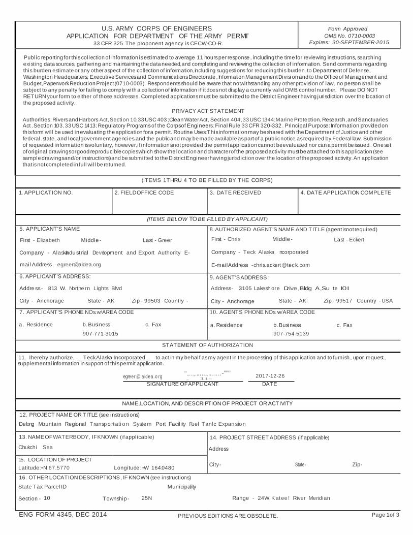
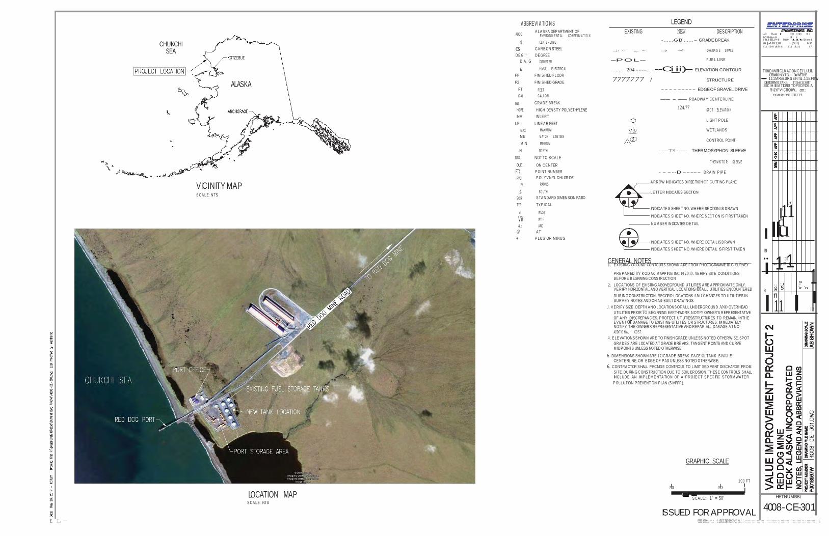
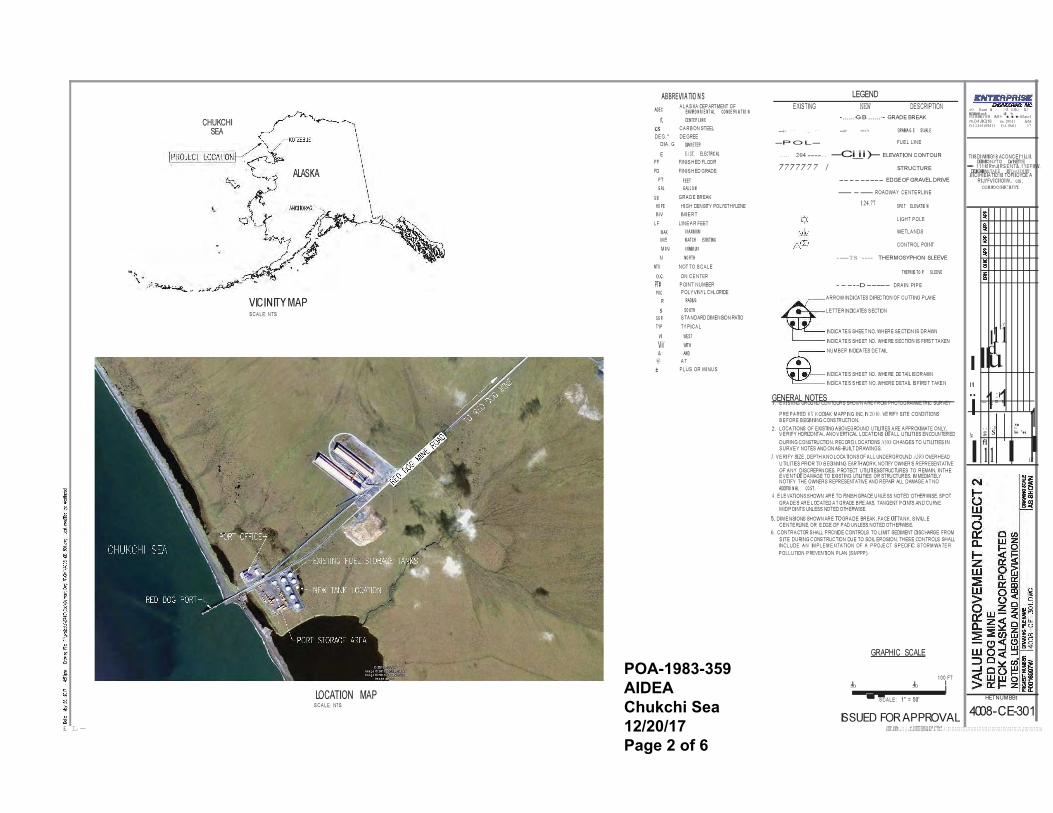
17. DIRECTIONS TO THE SITE The site is located at the Delong Mountain Regional Transportation System Port Facility, approximately 16 miles Southeast of Kivalina in the Northwest Arctic Borough of Alaska.
18. Nature of Activ ity (Description of project, include all f eatures)
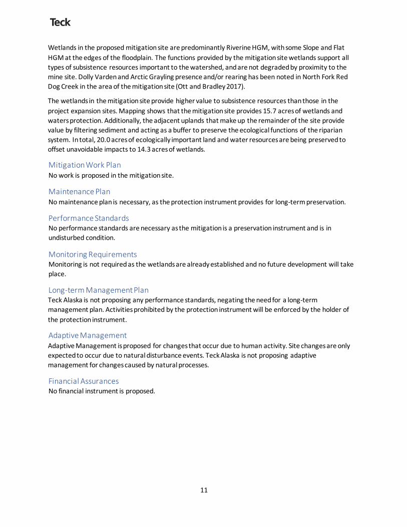
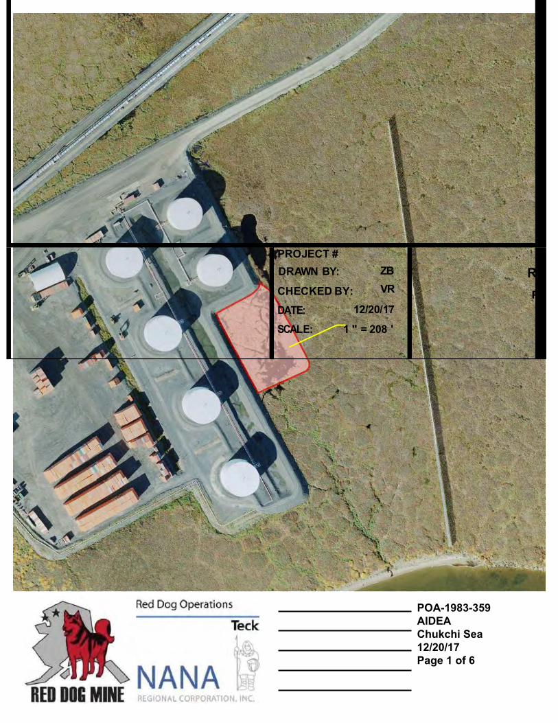
A new 3 million gallon diesel fuel tank is proposed to be built at the Delong Mountain Regional Transportation System Port Facility. The tank requires placement of fill material as a foundation for the new fuel tank as well as secondary containment in the event of a spill. The proposed pad and tank would be connected to the existing fuel storage pad. The fill pad will inlpact 1.3 acres of wetlands. The fill pad will be designed to be the containment area and the fill pad, including uses for sediment and stormwater control during construction , and equipment operations. All season construction will occur.
19. Project Purpose (Describe the reason or purpose of the project,see instructions)
Planned increases in fuel consumption at the Red Dog Mine require construction of an additional 3 million gallons of diesel storage. The facility is able to receive fuel deliveries from ocean going fuel barges from approximately early July to mid-October, depending on sea and ice conditions. To meet operational needs, the facility needs to be able to store approximately 9 months of diesel usage with a sufficient buffer to schedule fuel barge deliveries to minimize impacts to local subsistence activities.
USE BLOCKS 20 23 IF DREDGED AND/OR FILL MATERIA L IS TO BE DISCH AR GED
20. Reason(s) f or Discharge Expansion of the existing fuel storage facility requires discharge of fill material into wetlands adjacent to the existing facility.
21. Ty pe(s) of Material Being Discharged and the Amount of Each Ty pe in Cubic Yards: Ty pe Ty pe Ty pe Amount in Cubic Yards Amount in Cubic Yards Amount In Cubic Yards
11,460 sand/gravel fill
22 . Surf ace Area in Acres of Wetlands or Other Waters Filled (see instructions)
Acres 1.3 or
Linear Feet
23. Description of Av oidance ,Minimization, and Compensation (see instructions)
See attached
ENG FORM 4345, DEC 2014 Page 3 of 3
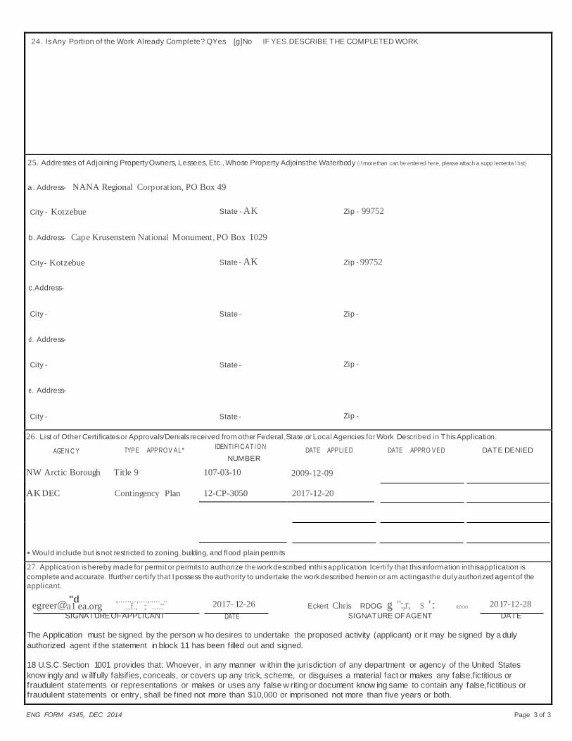
24. Is Any Portion of the Work Already Complete? QYes [g]No IF YES.DESCRIBE THE COMPLETED WORK
25. Addresses of Adjoining Property Owners, Lessees, Etc., Whose Property Adjoins the Waterbody (if more than can be entered here, please attach a supp lementa l list).
a . Address- NANA Regional Corporation, PO Box 49
City - Kotzebue State - AK Zip - 99752
b . Address- Cape Krusenstem National Monument, PO Box 1029
City - Kotzebue State - AK Zip - 99752 c.Address-
City - State - Zip - d. Address-
City - State - Zip - e. Address-
City - State - Zip -
26. List of Other Certificates or Approvals/Denials received from other Federal,State,or Local Agencies for Work Described in This Application.
AGEN C Y TYPE APPRO V AL* IDENTIFIC AT IO N DATE APPLIED DATE APPRO VED DATE DENIED NUMBER
NW Arctic Borough Title 9 107-03-10 2009-12-09
AK DEC Contingency Plan 12-CP-3050 2017-12-20
• Would include but is not restricted to zoning, building, and flood plain permits
27. Application is hereby made for permit or permits to authorize the work described in this application. Icertify that this information in this application is complete and accurate. Ifurther certify that I possess the authority to undertake the work described herein or am acting as the duly authorized agent of the applicant.
egreer@ "d .,........,....,....._.. 2017- 12-26 2017-12-28 a1 ea.org .,,f., ; ..... Eckert Chris RDOG g ":,r, s ': RDOO
SIGNATURE OF APPLICANT DATE SIGNATURE OF AGENT DATE The Application must be signed by the person w ho desires to undertake the proposed activity (applicant) or it may be signed by a duly authorized agent if the statement in block 11 has been f illed out and signed. 18 U.S.C.Section 1001 provides that: Whoever, in any manner w ithin the jurisdiction of any department or agency of the United States know ingly and w illfully falsif ies, conceals, or covers up any trick, scheme, or disguises a material fact or makes any false,f ictitious or fraudulent statements or representations or makes or uses any false w riting or document know ing same to contain any false,f ictitious or fraudulent statements or entry, shall be f ined not more than $10,000 or imprisoned not more than f ive years or both.
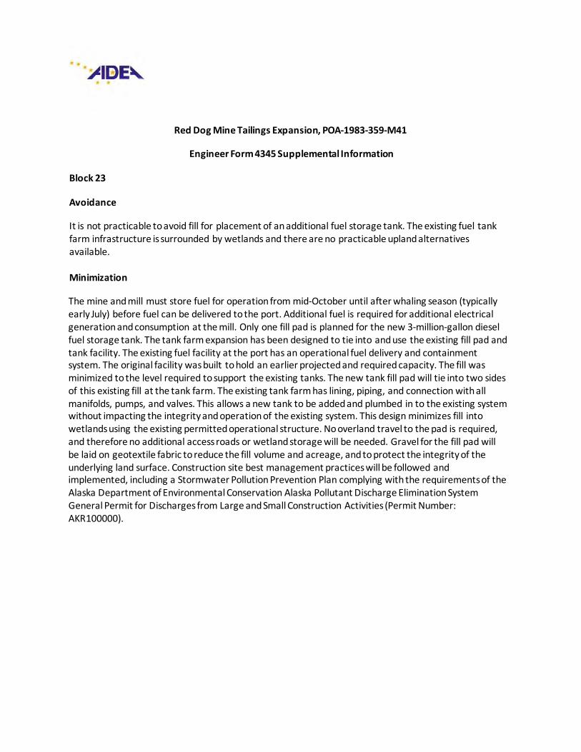
Red Dog Mine Tailings Expansion, POA-1983-359-M41
Engineer Form 4345 Supplemental Information
Block 23
Avoidance
It is not practicable to avoid fill for placement of an additional fuel storage tank. The existing fuel tank farm infrastructure is surrounded by wetlands and there are no practicable upland alternatives available.
Minimization
The mine and mill must store fuel for operation from mid-October until after whaling season (typically early July) before fuel can be delivered to the port. Additional fuel is required for additional electrical generation and consumption at the mill. Only one fill pad is planned for the new 3-million-gallon diesel fuel storage tank. The tank farm expansion has been designed to tie into and use the existing fill pad and tank facility. The existing fuel facility at the port has an operational fuel delivery and containment system. The original facility was built to hold an earlier projected and required capacity. The fill was minimized to the level required to support the existing tanks. The new tank fill pad will tie into two sides of this existing fill at the tank farm. The existing tank farm has lining, piping, and connection with all manifolds, pumps, and valves. This allows a new tank to be added and plumbed in to the existing system without impacting the integrity and operation of the existing system. This design minimizes fill into wetlands using the existing permitted operational structure. No overland travel to the pad is required, and therefore no additional access roads or wetland storage will be needed. Gravel for the fill pad will be laid on geotextile fabric to reduce the fill volume and acreage, and to protect the integrity of the underlying land surface. Construction site best management practices will be followed and implemented, including a Stormwater Pollution Prevention Plan complying with the requirements of the Alaska Department of Environmental Conservation Alaska Pollutant Discharge Elimination System General Permit for Discharges from Large and Small Construction Activities (Permit Number: AKR100000).
Compensatory Mitigation Plan
Red Dog Mine Tailings Expansion,
Red Dog Mine Waste Dump Extension, and
Delong Mountain Regional Transportation System Port Facility Fuel Tank Expansion
1
Contents Project Description......................................................................................................................1
Available Mitigation Credits ..........................................................................................................4
Watershed Approach...................................................................................................................4
Proposed Compensatory Mitigation Plan ........................................................................................5
Goals and Objectives ................................................................................................................5
Site Selection ..........................................................................................................................5
Restoration and Enhancement ...............................................................................................5
Preservation........................................................................................................................5
Site Identification .................................................................................................................6
Site Protection ........................................................................................................................8
Baseline Conditions .................................................................................................................8
Project Sites ........................................................................................................................8
Proposed Mitigation Site .......................................................................................................9
Reference Site ................................................................................................................... 10
Determination of Credits ........................................................................................................ 10
Mitigation Work Plan ............................................................................................................. 11
Maintenance Plan.................................................................................................................. 11
Performance Standards .......................................................................................................... 11
Monitoring Requirements ....................................................................................................... 11
Long-term Management Plan .................................................................................................. 11
Adaptive Management ........................................................................................................... 11
Financial Assurances .............................................................................................................. 11
References .............................................................................................................................. 12
Figures Figure 1 Red Dog Creek Proposed Mitigation Site........................................................................7
Tables Table 1 Project Sites Wetlands ..................................................................................................9 Table 2 Mitigation Site HGM Classification ..................................................................................9 Table 3 Mitigation Site Cowardin Classification .......................................................................... 10
2
Acronyms AMSL Above Mean Sea Level
CFR Code of Federal Regulations
HGM Hydrogeomorphic
ILF In-Lieu Fee
Mitigation Rule 33 CFR Parts 325 and 332
NANA NANA Regional Corporation
PRM Permittee-Responsible Mitigation
USACE United States Army Corps of Engineers
WOUS Waters of the United States
3
Project Description The ongoing operation of the Red Dog Mine by Teck Alaska requires an expanded footprint. There is a need to increase the capacity for Tailings and Main Waste Dump facilities to contain mine and mill waste. Additionally, there is a need to increase capacity for fuel storage at the port facility. The port facility is permitted to AIDEA by the United States Army Corps of Engineers (USACE) and operated through agreement by Red Dog, Teck Alaska. A wetland delineation for all three areas was completed in 2017 (WHPacific 2017) using the 2007 Alaska Regional Supplement (USACE 2007).
POA 1984-12-M49 authorized the Red Dog Tailings Facility to an elevation of 986 foot Above Mean Sea Level (AMSL). This project is proposing to increase the tailings facility from the currently approved level of 986 feet AMSL to 1006 feet AMSL. The project involves the raising of the Red Dog Tailings Main Dam (AK00201) and the Red Dog Tailings Back Dam (AK00303) from a current crest elevation of 986 feet AMSL to 1006 feet AMSL in multiple phases between 2018 and 2024. The increased operating elevation requires the relocation of the West Tailings Road and the Main Haul Road. To minimize disturbance, the realigned roads have been designed, where possible, to fall within the ultimate footprint of the expanded tailings facility and to avoid wetlands in areas outside of the tailings facility footprint. This project will require the placement of 20,104 cubic yards of fill material into 12.5 acres of wetlands.
POA-1984-12, March 2000, this modification for the Main Waste Dump Extension expired without the Main Waste dump being expanded. A portion of the Main Waste Dump South Extension was permitted by this modification. WHPacific completed a new wetland delineation for the project area in 2017. Additionally, the request for the Qanaiyaq extension has been removed from the proposed project further avoiding wetland impact. To ensure the surface water from the stockpile remains in the South Fork Red Dog Creek drainage and flows into the Red Dog Mine Tailings impoundment, the footprint of the Main Waste Dump Extension has been reduced to 32.5 acres (total) to keep it well below the drainage divide between the South Fork Red Dog Creek and Bons Creek drainages. These actions have reduced the required wetland fill for this project to 0.5 acres from the originally proposed 44 acres.
POA 1983-359-MOO authorized the expansion of the Fuel Storage Facility at the Delong Mountain Regional Transportation System Port Facility. Planned increases in fuel consumption at the Red Dog Mine require construction of an additional 3 million gallon diesel storage tank. The facility receives fuel deliveries from ocean going fuel barges from approximately early July to mid-October, depending on sea and ice conditions. To meet operational demands the facility needs to be able to store approximately 9 month’s diesel supply including a sufficient buffer-volume to allow for the scheduling of fuel barge deliveries to minimize impacts to local subsistence activities. This project is for the placement of 11,460 cubic yards of fill material into 1.3 acres of wetlands for the expansion of the existing tank farm. The fill is required to provide a sound foundation for the new fuel storage tank and to provide the required secondary containment volume. The secondary containment for the new fuel storage tanks will be connected to the existing fuel storage pad, allowing for sufficient secondary containment for spill prevention while minimizing additional surface disturbance. The project is scheduled to begin in early 2018 upon issuance of the permit and to be completed mid-2019.
4
Available Mitigation Credits On April 10, 2008, the USACE and the Environmental Protection Agency published regulations (33 Code of Federal Regulations (CFR) Parts 325 and 332) entitled, “Compensatory Mitigation for Losses of Aquatic Resources,” (Mitigation Rule). One of the primary goals of the regulations is to improve the quality and success of compensatory mitigation plans. The Mitigation Rule emphasizes the selection of compensatory mitigation sites on a watershed basis and established equivalent standards for all three types of compensatory mitigation mechanisms: mitigation banks, In-Lieu Fee (ILF) programs, and permittee-responsible mitigation (PRM) plans. In addition, the Mitigation Rule established a preference hierarchy for mitigation mechanisms based upon their likelihood of projects being both successful and sustainable:
1. Purchase of mitigation bank credits 2. Purchase of ILF program credits 3. PRM under a watershed approach
Compensatory mitigation provided by an approved mitigation bank or ILF program is presumed to be environmentally preferable to PRM. This mitigation involves larger, more ecologically valuable aquatic resources and normally more rigorous scientific and technical analysis. Mitigation banks and ILF programs are approved and implemented prior to the adverse impacts to aquatic resources associated with individual projects. Early implementation reduces temporal losses and uncertainty regarding the success of mitigation activities. No mitigation banks or ILF programs with service areas currently exist that include or overlap the project area. A search of the Regulatory ILF and Bank Information Tracking System on January 2, 2018 showed no available credits. Therefore, there are no mitigation bank or ILF credits available in the project watershed. Red Dog Mine must develop PRM under a watershed approach to supply wetland credits.
Watershed Approach The goal of PRM under a watershed approach is to maintain and improve the quality and quantity of aquatic resources within the impact watershed through the selection of compensatory mitigation projects. In developing their PRM project priorities, Red Dog Mine evaluated their proposed project wetland impacts and cumulative impacts of past activities. This included reviewing potential sites within the watershed, and discussing issues with the local communities to help identify potential mitigation opportunities.
The proposed project site is located within the Wulik-Kivalina Rivers Hydrologic Unit Code 8 watershed (19050404). The Wulik-Kivalina Rivers watershed is almost entirely undisturbed and has limited development pressure. The limited development in the region restricts restoration opportunities. There is one community within the watershed, Kivalina, with an estimated 2016 population of 383 people. The watershed covers an area of approximately 1,640,315 acres of land. This compensatory mitigation plan has been developed considering the resources, uses, and people within this watershed.
5
Proposed Compensatory Mitigation Plan Goals and Objectives The goals and objectives of this plan are to mitigate for the unavoidable fill impacts to 14.3 acres of Waters of the United States (WOUS) authorized by modifications to Department of the Army permits POA-1983-359, POA-1984-12-M49, POA-1984-12-M51. Avoidance and minimization has been completed for the proposed actions to the maximum extent practicable. Compensatory mitigation will be provided through the preservation of an ecologically and socio-economically important site in proximity to the Red Dog Mine.
Preservation will be accomplished via a deed restriction on land owned by NANA Regional Corporation (NANA). Preservation is appropriate under the 2008 Mitigation Rule under the criteria of 33 CFR 332.3(h).
Site Selection Restoration and Enhancement The Red Dog Mine was permitted with as small as a footprint as possible to avoid and minimize impacts to Wetlands and WOUS. There were no impacts outside of those necessary to operate the mine and associated facilities (port, road, camp, airstrip, etc.). As the mine is operating and is expected to continue to operate, there are no restoration opportunities associated with the existing and past mine disturbance. Several work pads and roads were considered for removal and restoration, however, the Teck Alaska Exploration and Operations teams reviewed these areas and found them to be necessary for ongoing and future operations. The mine continues to operate, process ore, and expand operations in the watershed. The need for uplands pads is at a premium at both the port and the mine site. Additionally, there have been no other practicable aquatic resource impacts identified within the watershed that could be restored to provide PRM credits.
Preservation The proposed mitigation site meets the following conditions:
1. The preserved site provides habitat, ground water discharge, flood flow moderation, nutrient cycling, and buffers for the watershed,
2. It contributes to the ecological sustainability of the watershed, 3. It is the most appropriate and practicable PRM project in the watershed, 4. The resources are under threat of destruction or adverse modification, and 5. The site will be protected for a period of 99 years.
The Wulik-Kivalina Rivers watershed has minimal development. There is one community and public airport within the watershed at Kivalina. The only permanent all-season road within the watershed connects Red Dog Mine to a port facility at the coast. Other travel occurs along winter trails. There are limited impacts to the watershed from tourism, primarily from sport fishing for Dolly Varden on the Wulik River.
Land ownership in the watershed is federal, state, and native. There is currently only one other proposed development in the watershed, the proposed evacuation road from the village of Kivalina to a location inland approximately seven miles to the northwest.

6
Site Identification Teck Alaska worked with NANA to identify lands in proximity to the Red Dog Mine that have a threat of destruction or adverse modification. Along the North Fork of Red Dog Creek, there is an area that has been considered for natural gas exploration and mine development including the drilling of exploration gas wells (Figure 1). The North Fork of Red Dog Creek has a long history of fish studies and habitat inventory. This data substantiates the fish value of the area (Ott and Bradley 2017).
An area of high-value wetland riparian habitat in this exploration area is proposed to be protected with a deed restriction.
This site provides important function for the watershed by providing habitat and water quality for anadromous and resident fish, both at the site and downstream, and for terrestrial mammals and vegetative subsistence resources. Permanently protecting this area will contribute to the ecological sustainability of the watershed by helping to maintain subsistence-related aquatic resources. Additionally, the North Fork of Red Dog Creek flows to the Wulik River, which is the source of drinking water for Kivalina. The area is under potential threat of development from natural gas and mineral development. A permanent deed restriction will ensure the stream and riparian areas are buffered from any future development.
7
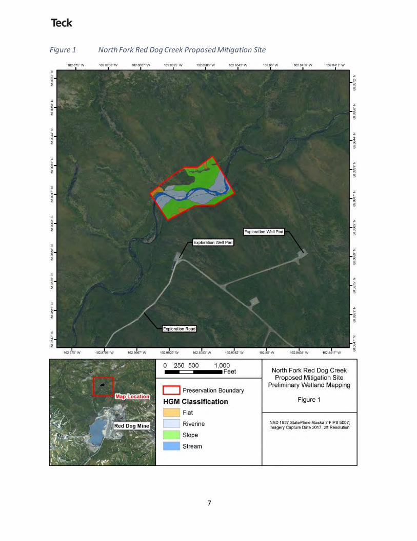
Figure 1 North Fork Red Dog Creek Proposed Mitigation Site
8
Site Protection NANA owns the surface and subsurface rights to the proposed mitigation site. Teck Alaska will work with NANA to establish a deed restriction to ensure long-term protection of the site. The instrument will describe the allowed and prohibited uses of the mitigation site. Teck Alaska will provide documentation to the USACE from NANA, consenting to the restrictions on development.
Subsistence uses (including, but not limited to, hunting, fishing, trapping, egg gathering, and vegetation collection) would be allowed in the mitigation site without restriction. Reasonable access, ingress, and egress by vehicles including snowmobile, all-terrain vehicle, helicopter, and foot will continue to be allowed. Other activities, such as crossing the mitigation site for winter cross-country travel, will be determined on a case-by-case basis by the holder of the protection instrument for the parcel. The holder will have the right to enforce site protective measures associated with the instrument. The following activities will be prohibited by the site protection instrument, without prior consent from USACE:
• Dredging or excavating of any soils, sediments, and other substrates. • Discharge of dredge or fill materials. • Construction of durable structures, both permanent and temporary. • Disturbance of soil, sediment, and other substrates by mechanical equipment and
transportation vehicles. • Surface or near-surface mining and related activities that adversely impact the WOUS status of
the mitigation site. • Vegetation removal, destruction, cutting, trimming, mowing, alteration, or spraying with
biocides, except where allowed for subsistence activities and for control, elimination, or management of nonnative, exotic, or invasive vegetation.
• Storage, abandonment, stockpiling, or disposal of any earthen materials, debris, refuse, supplies, durable materials, or other manmade objects.
• Changing the surface hydrology of the area by ditching, pumping, damming, or other dewatering or hydrating methods.
• Mechanized snow-and ice-clearing operations and construction of snow/ice structures including ice roads and ice pads.
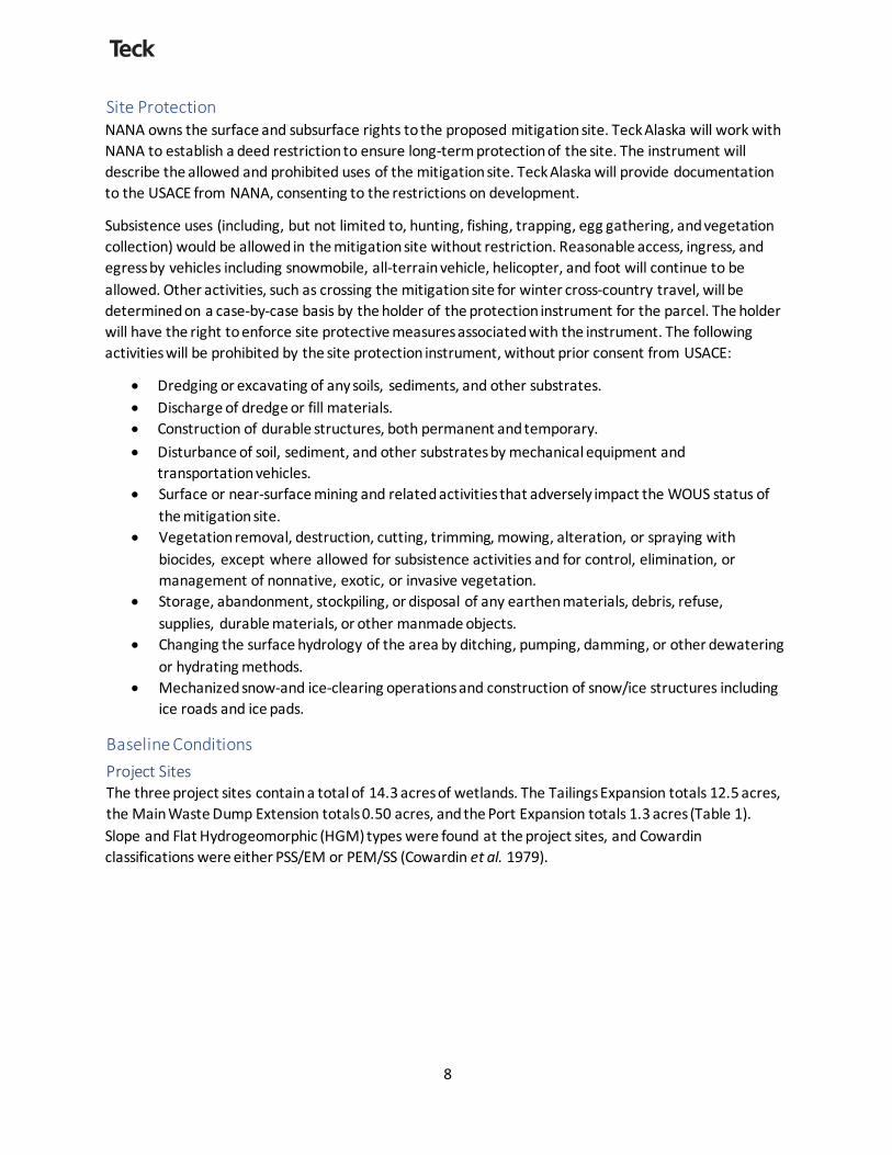
Baseline Conditions Project Sites The three project sites contain a total of 14.3 acres of wetlands. The Tailings Expansion totals 12.5 acres, the Main Waste Dump Extension totals 0.50 acres, and the Port Expansion totals 1.3 acres (Table 1). Slope and Flat Hydrogeomorphic (HGM) types were found at the project sites, and Cowardin classifications were either PSS/EM or PEM/SS (Cowardin et al. 1979).
9
Table 1 Project Sites Wetlands
Project Site HGM Classification
Cowardin Classification
Area (Acres)
Tailings Expansion Slope PSS/EM 12.5 Waste Dump Extension Slope PSS/EM 0.5 Port Expansion Flat PEM/SS 1.3
Total Wetlands 14.3
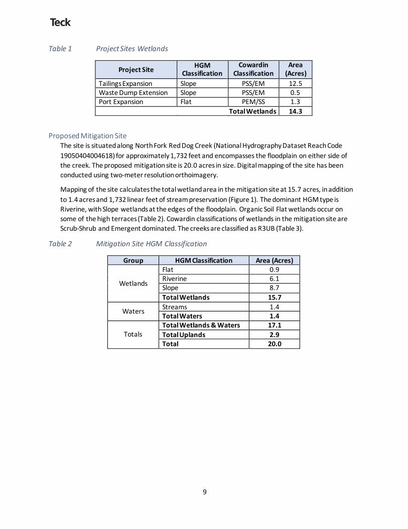
Proposed Mitigation Site The site is situated along North Fork Red Dog Creek (National Hydrography Dataset Reach Code 19050404004618) for approximately 1,732 feet and encompasses the floodplain on either side of the creek. The proposed mitigation site is 20.0 acres in size. Digital mapping of the site has been conducted using two-meter resolution orthoimagery.
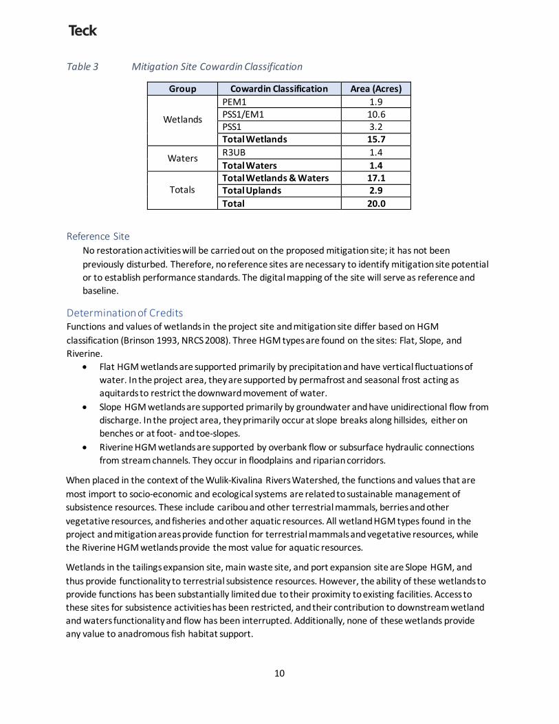
Mapping of the site calculates the total wetland area in the mitigation site at 15.7 acres, in addition to 1.4 acres and 1,732 linear feet of stream preservation (Figure 1). The dominant HGM type is Riverine, with Slope wetlands at the edges of the floodplain. Organic Soil Flat wetlands occur on some of the high terraces (Table 2). Cowardin classifications of wetlands in the mitigation site are Scrub-Shrub and Emergent dominated. The creeks are classified as R3UB (Table 3).
Table 2 Mitigation Site HGM Classification
Group HGM Classification Area (Acres)
Wetlands
Flat 0.9 Riverine 6.1 Slope 8.7 Total Wetlands 15.7
Waters Streams 1.4 Total Waters 1.4
Totals
Total Wetlands & Waters 17.1 Total Uplands 2.9 Total 20.0
10
Table 3 Mitigation Site Cowardin Classification
Group Cowardin Classification Area (Acres)
Wetlands
PEM1 1.9 PSS1/EM1 10.6 PSS1 3.2 Total Wetlands 15.7
Waters R3UB 1.4 Total Waters 1.4
Totals
Total Wetlands & Waters 17.1 Total Uplands 2.9 Total 20.0
Reference Site No restoration activities will be carried out on the proposed mitigation site; it has not been previously disturbed. Therefore, no reference sites are necessary to identify mitigation site potential or to establish performance standards. The digital mapping of the site will serve as reference and baseline.
Determination of Credits Functions and values of wetlands in the project site and mitigation site differ based on HGM classification (Brinson 1993, NRCS 2008). Three HGM types are found on the sites: Flat, Slope, and Riverine.
• Flat HGM wetlands are supported primarily by precipitation and have vertical fluctuations of water. In the project area, they are supported by permafrost and seasonal frost acting as aquitards to restrict the downward movement of water.
• Slope HGM wetlands are supported primarily by groundwater and have unidirectional flow from discharge. In the project area, they primarily occur at slope breaks along hillsides, either on benches or at foot- and toe-slopes.
• Riverine HGM wetlands are supported by overbank flow or subsurface hydraulic connections from stream channels. They occur in floodplains and riparian corridors.
When placed in the context of the Wulik-Kivalina Rivers Watershed, the functions and values that are most import to socio-economic and ecological systems are related to sustainable management of subsistence resources. These include caribou and other terrestrial mammals, berries and other vegetative resources, and fisheries and other aquatic resources. All wetland HGM types found in the project and mitigation areas provide function for terrestrial mammals and vegetative resources, while the Riverine HGM wetlands provide the most value for aquatic resources.
Wetlands in the tailings expansion site, main waste site, and port expansion site are Slope HGM, and thus provide functionality to terrestrial subsistence resources. However, the ability of these wetlands to provide functions has been substantially limited due to their proximity to existing facilities. Access to these sites for subsistence activities has been restricted, and their contribution to downstream wetland and waters functionality and flow has been interrupted. Additionally, none of these wetlands provide any value to anadromous fish habitat support.
11
Wetlands in the proposed mitigation site are predominantly Riverine HGM, with some Slope and Flat HGM at the edges of the floodplain. The functions provided by the mitigation site wetlands support all types of subsistence resources important to the watershed, and are not degraded by proximity to the mine site. Dolly Varden and Arctic Grayling presence and/or rearing has been noted in North Fork Red Dog Creek in the area of the mitigation site (Ott and Bradley 2017).
The wetlands in the mitigation site provide higher value to subsistence resources than those in the project expansion sites. Mapping shows that the mitigation site provides 15.7 acres of wetlands and waters protection. Additionally, the adjacent uplands that make up the remainder of the site provide value by filtering sediment and acting as a buffer to preserve the ecological functions of the riparian system. In total, 20.0 acres of ecologically important land and water resources are being preserved to offset unavoidable impacts to 14.3 acres of wetlands.
Mitigation Work Plan No work is proposed in the mitigation site.
Maintenance Plan No maintenance plan is necessary, as the protection instrument provides for long-term preservation.
Performance Standards No performance standards are necessary as the mitigation is a preservation instrument and is in undisturbed condition.
Monitoring Requirements Monitoring is not required as the wetlands are already established and no future development will take place.
Long-term Management Plan Teck Alaska is not proposing any performance standards, negating the need for a long-term management plan. Activities prohibited by the protection instrument will be enforced by the holder of the protection instrument.
Adaptive Management Adaptive Management is proposed for changes that occur due to human activity. Site changes are only expected to occur due to natural disturbance events. Teck Alaska is not proposing adaptive management for changes caused by natural processes.
Financial Assurances No financial instrument is proposed.
12
References Brinson, M.M. 1993. A Hydrogeomorphic Classification for Wetlands, Technical Report WRP-DE-4, US
Army Corps of Engineers Waterways Experiment Station, Vicksburg, MS.
Cowardin, L. M., V. Carter, F.C. Golet, and E.T. LaRoe. 1979. Classification of Wetlands and Deepwater Habitats of the United States. US Department of the Interior, Fish and Wildlife Service, Office and Biological Services, Washington, DC.
Natural Resources Conservation Service. 2008. Hydrogeomorphic Wetland Classification System: An Overview and Modification to Better Meet the Needs of the Naturl Resources Conservation Service. Technical Note No. 190-8-76.
Ott, A.G. an P.T. Bradley. 2017. Aquatic Biomonitoring at Red Dog Mine, 2016. Alaska Department of Fish and Game. Technical Report No. 17-07.
US Army Corps of Engineers (USACE). 2017. Regional Supplement to the Corps of Engineers Wetland Delineation Manual: Alaska Region, (Version 2.0), ed. J.S. Wakeley, R.W. Lichvar, and C.V. Noble. ERDC/EL TR-07-24. Vicksburg, MS: U.S. Army Engineer Research and Development Center.
WHPacific. 2017. Delineation of Wetlands and Other Waters for: Red Dog Mine Tailings Pond Dam Raise, Dump Expansion, and Port Improvements. Prepared for Teck Alaska Incorporated. November 20, 2017.
PROJECT # DRAWN BY: ZB
CHECKED BY: VR
DATE: 12/20/17
SCALE: 1 " = 208 '
R P
I 1 1 .. :: I 'N° '°
I
I
I I
I
ABBREVI A TIO N S ADEC A LA S KA DEP ARTMENT OF
ENVIRO N M E NT AL CO NSE RV A T I O N rt. CENTER L I N E
cs CA RB ON STEEL
LEGEND EXISTING NEW DESCRIPTION
- ......·GB ......·- GRADE BREAK
---i> · ·· .. , . ·· · ---i> - - - ->- DRAINA G E SWAL E
«0 Rant I !: !125 Q: /18Q J. 1'1£I T llClllM9.m:8 9Jll l: W: : . f'H.ll!llllll,1Wlf lM10 iit ll.Saro:I m.{»1JIC(18 m.{901) JeM f),1; (201)8$411 f),1; (8a1) 17
DE G. ' DE GREE DIA , G DIAM ETER --POL-- FUE L LINE
VICINITY MAP S CA LE: NTS
E EA ST, EL ECTRIC AL FF FINIS HED FLOOR FG FINIS HED GRADE
FT FEET G AL G AL L O N
G B GRA DE BREAK HO PE HIGH DENSITY POLYETHYLENE INV IN\IE RT
LF LINE A R FEET M AX M AXIM UM M E M ATCH EXIST ING M IN M INIM UM
N NO RTH NTS NOT TO S CA LE
o.c. ON CE NTER PT# P OINT NUMBER PVC P OLY VINYL CHLORIDE
R RADIUS
s SO UTH SO R S TA NDARD DIMENSION RATIO TYP TY P ICA L
VI WEST
Vi/ WITH & : AND
@ A T ± P LUS OR M INUS
..... 204 ----.. --Ci_ii)-- ELEVATION CONTOUR
7777777 / STRUCTURE
-- - - - - - - - EDGE OF GRAVEL DRIVE
-- - -- ROA DWA Y CE NTE RLINE
124.77 SPO T EL EVAT IO N
LIGHT P OLE
WE TLA NDS
CONTROL POINT
- ----TS· ---- THERMOSYPHON SLEEVE
THERM IS TO R SL EEVE
- - - --D ----- DRA IN P IP E
A RROW INDICATES DIRECTION OF CUTTING P LANE
LE TTE R INDICATES S ECTION
INDICA TE S SHEE T NO. WHERE SE CTION IS DRAWN
INDICA TE S SHE ET NO. WHE RE S ECTION IS FIRS T TA KEN
NUM B ER INDICA TES DE TAIL
INDICA TE S SHE ET NO. WHE RE DE TAIL IS DRAWN INDICA TE S S HE ET NO. WHERE DETA IL IS FIRS T TAKE N
GENERAL NOTES 1. E X ISTING GROUND CONTOURS SHOV/N A RE FROM PHOTOGRAMME TRIC SURVEY
Tl l8DIWl l'llG18 ACONCE l '1 IJ.l l .
DEllMllON.YTO Da'INETl !E • 111M Rm JIRS E NT& .11E Fl lW.
DE.lllGlllllWJ.TAKE lllTQACCOIJllT .Il lCIHIE IA TIO!l8 TOFl lOYDE A
RIJY. FV ICl lOIW.. cm; CGl'l.llOO'HICllJT'f.
;i
I11 I IIdu .l!.I :i
"" <C m u
P RE P A RED 8Y K ODIAK M APP ING INC, IN 2010. VE RIFY S ITE CONDITIONS B E FORE B EGINNING CONS TRUCTION.
2. LOCA TIONS OF EXISTING A BOVEGROUND UTILITIES A RE A PPROXIMATE ONLY. V E RIFY HORIZONTAi.. ANO V ERTICAL LOCATIONS or A LL UTILITIES ENCOUNTERED
g s -.... -.... !e " "
DURING CONSTRUCTION. RECORD LOCATIONS ANO CHANGES TO UTILITIES IN S URV E Y NOTES AND ON AS -BUILT DRAWINGS.
J. V E RIFY SIZE , DEPTH A NO LOCA TIONS OF A LL UNDERGROUND ANO OVERHEAD UTILITIES PRIOR TO B EGINNING EARTHWORK. NOTIFY OWNER'S REPRESENTATIVE OF A NY DISCREPANCIES. P ROTECT UTILITIES/STRUCTURES TO REMAIN. IN THE E V E NT or DA MAGE TO EXISTING UTILITIES OR STRUCTURES. IM MEDIATELY NOTIFY THE OWNERS REPRESENTATIVE AND REPAIR ALL DAMAGE A T NO ADDIT IO N AL CO ST .
4. E LE VATIONS S HOWN ARE TO FINISH GRA DE UNLE SS NOTED OTHERWISE. SP OT GRA DE S ARE LOCATED A T GRADE B RE .AKS, TANGENT P OINTS AND CURVE M IDP OINTS UNLESS NOTED OTHERWISE.
5. DIM E NSIONS SHOWN ARE TO GRA DE BREAK . FA CE or TA NK . S IV/IJ..E CE NTE RLINE, OR E DGE OF P AD UNLESS NOTED OTHERWIS E.
6. CONTRA CTOR S HALL P RCNlDE CONTROLS TO LIMIT SEDIMENT DISCHARGE FROM S ITE DURING CONS TRUCTION DUE TO SOIL EROSION. THES E CONTROLS SHALL INCLUDE A N IM P LE M E NTA TION OF A P ROJE CT S P ECIFIC S TORM WA TE R P OLLUTION P REVENTION P LAN (S IVPPP ).
fl
11 ii!
GRAPHIC SCALE
50 ---- 50
100 FT I I
S CA LE: NTS
S CA LE : 1" = 50'
ISSUED FOR APPROVAL
HETNUMBBt
4008-CE-301 £ L- O;I;U;;C;l;N;M;;..;;,;,;;f,;lS=IZEE=QU;A;L;:S:2='l;",';3:f;'..&:;;;;;;;;;;;;;;;;;;;;;;;;;;;;;;;;;;;;;;;;;;;;:;;,;;;;;;;;;;:a
CHUKCHI SEA
ALASKA
LOCATION MAP
1
i.5.
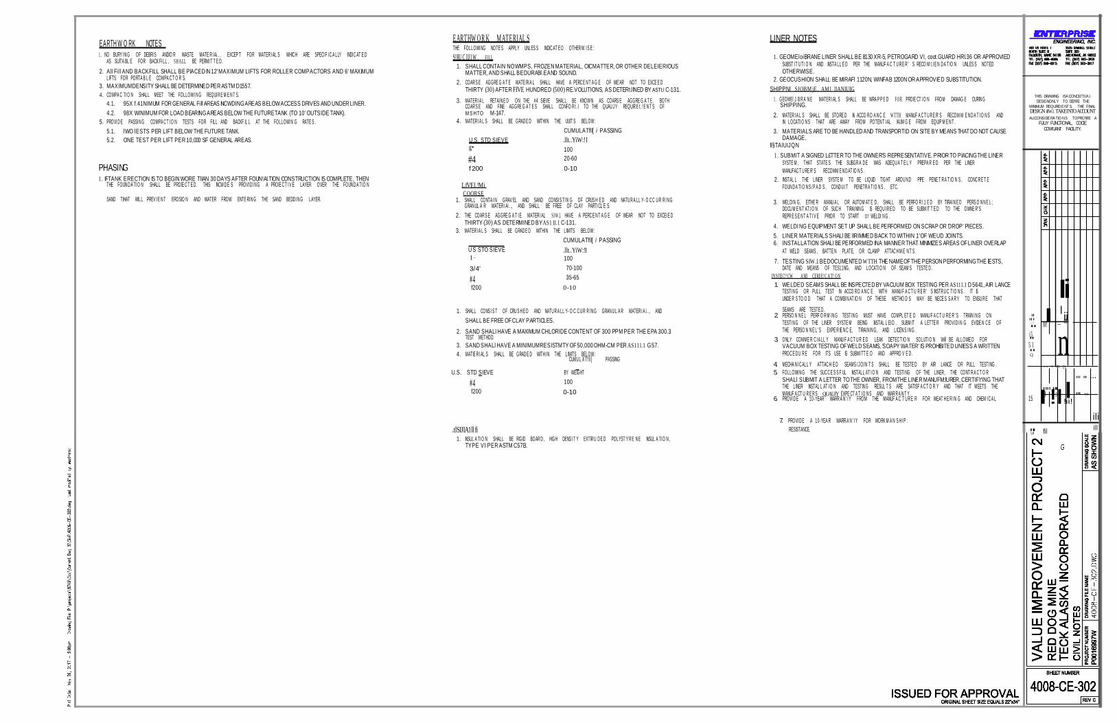
EARTH W O RK NOTES 1 . NO BURY I N G OF DEBRI S AND/O R WASTE MATE R I Ai .. , EXCEP T FOR MATER I AL S WHIC H ARE SPECI F I C A LLY INDI C AT E D
AS SUITA BL E FOR BACK FI LL , SH A LL BE PERMI T T E D . 2. All Fill AND BACKFILL SHALL BE PlACED IN 12' MAXIMUM LIFTS FOR ROLLER COMPACTORS AND 6' MAXIMUM
LIFTS FOR PORTA B L E COMPA C T O R S. 3. MAXIMUM DENSITY SHALL BE DETERMINED PER ASTM D1557. 4. COMPA C TI O N SHALL MEET THE FOLLOW I N G REQUI R E M E N T S.
4.1. 95X f.41NIMUM FOR GENERAL Fill AREAS INCWDING AREAS BELOW ACCESS DRIVES AND UNDER LINER. 4.2. 98X WINIMUM FOR LOAD BEARING AREAS BELOW THE FUTURE TANK (TO 10' OUTSIDE TANK).
5. PROVI D E PASSI N G COMPA C T I O N TESTS FOR FILL AND BACKF IL L AT THE FOLLOWI N G RATE S . 5.1. lWO lESTS PER LIFT BELOW THE FUTURE TANK. 5.2. ONE TEST PER LIFT PER 10,000 SF GENERAL AREAS.
EARTHW O R K MATERIAL S THE FOLLOWI NG NOTE S APPLY UNLES S INDIC AT E D OTHER W I S E : S!RU C llJ I W . FILL
1. SHALL CONTAIN NO WMPS, FROZEN MATERIAL, OIC MATTER, OR OTHER DELEIERIOUS MATTER, AND SHALL BE DURABl.E AND SOUND.
2. COAR S E AGGRE G A T E MATE RI A L SHALL HAVE A PERC E N T A G E OF WE'AR NOT TO EXCE E D THIRTY (30) AFTER FIVE HUNDRED (500) RE.VOLUTIONS, AS DETERt.llNED BY ASTt.l C-131.
3. MATER I A L RETAI N E D ON THE #4 SIEVE SHALL BE KNOW N AS COARS E AGGRE G A T E . BOTH COAR S E AND FINE AGGRE G A T E S SHALL CONFO R t . I TO THE QUAU J Y REQUIR E t . ! E N T S OF M S HTO M-147.
4. MATER I A L S SHALL BE GRAD E D WITHI N THE Ut.IIT S BELOW : CUMULATfll[ i PASSING
U.S. STD SIEVE .llt..YiW:!I g• 100
LINER NOTES
1. GEOMEloiBRANE LINER SHALL BE 8130 XR-5, PETROGARD VI, coot.GUARD HRl.36 OR APPROVIED SUBST I T U TI O N AND INSTA LL E D PER THE MANUF A C T U R E R ' S RECO M t. I E N D A T IO N UNLES S NOTED OTHERWISE.
2. GEOCUSHION SHALL BE MIRAFl 1120N, WINFAB 1200N OR APPROVIED SUBSTITUTION. SHIPPNl SJOBM jE . AM l llANIUIG
1 . GEOMEl .1 B R A N E MATER I AL S SHALL BE WRA P P E D FO R PROlE CT I O N FROM DAMAG E DURIN G SHIPPING.
2. MATER I A L S SHALL BE STORE D IN ACCO R D A N C E W TTH MANUF A C T U R E R' S RECOM M E N D A T I O N S AND IN LOCATI O N S THAT ARE AWAY FROM POTEN T I AL !Al.IM G E FROM EQUIP M E N T .
3. MATERIALS ARE TO BE HANDLED AND TRANSPORTID ON SITE BY MEANS THAT DO NOT CAUSE DAMAGE.
ll§TAlUIJQN
THIS DRAWING ISA CONCEl'Tl.IA I. DESIGNONLY TO DEl'lllE THE
MINIMUM REQURE!.ENT S. THE FINAL DESIGN illW.l. TAKE INTO ACCOUNT AU.CONSIDERATIO NS TOPRO'llllE A
F\JU.Y F\JNCTIONAL, COClE COW'UANT FACILITY.
PHASING 1. IF TANK ERECTION IS TO BEGIN WORE TllAN 30 DAYS AFTER FOUN!Al.TION CONSTRUCTION IS COMPLETE, THEN
THE FOUN D A TI O N SHALL BE PROlE C T E D . THIS INCW D E S PROVI D I N G A PROlE C T I V E LAYER OVER THE FOUN D A TI O N
#4 f 200
LfVEl.!Mi COORSE
20-60 0-10
1. SUBMIT A SIGNED L£TTER TO THE OWNER'S REPRESENTATIVE. PRIOR TO PlACING THE LINER SYSTE M , THAT STATE S THE SUBGR A D E WAS ADEQU A T E L Y PREPA R E D PER THE LINER MANUFAC T U RE R' S RECOMM E N D AT IO N S .
2. INSTAL L THE LINER SYSTE M TO BE LIQUID TIGHT AROU N D PIPE PENE T R A T IO N S , CONC R E T E FOUN D A TI O N S / P A D S , COND U I T PENETR A TI O N S , ETC.
SAND TIHAT WILL PREV I E N T EROSIO N AND WATER FROW ENTE RI N G THE SAND BEDD I N G LAYER. 1. SHALL CONTA I N GRAV EL AND SAND CONSI S TI N G OF CRUS H E D AND NATU R A LL Y- O C C U R R I N G GRAN UL A R MATER I Ai . ., AND SHALL BE FREE OF CLAY PARTI CL E S.
2. THE COAR S E AGGRE G A T I E MATER I AL SIW .l. HAVE A PERC E N T A G E OF WEAR NOT TO EXCEI E D THIRTY (30) AS DETERMINED BY AS11l.1 C-131.
3. MATER I A L S SHALL BE GRAD E D WITHI N THE LIMITS BELOW : CUMULATfll[ i PASSING
3. WELDI N G, EITHE R MANU A L OR AUTOM AT E D , SHALL BE PERFO R l .1 E D BY TIRAI N E D PERS O N N E L ; DOCU M E N T AT I O N OF SUC H TIRAI NIN G IS REQU I R E D TO BE SUBM IT T E D TO THE OWNE R' S REPR E S E N T A T l V E PRIOR TO START O f WELDI N G .
4. WELDI NG EQUIPMENT SET UP SHALL BE PERFORMED ON SCRAP OR 'DROP' PIECES. 5. LINER MATERIALS SHALl BE llRIMMED BACK TO WITHIN 1' OF WEUD JOINTS. 6. INSTALLATION SHALl BE PERFORMED IN A MANNER THAT MINIMIZES AREAS OF LINER OVERLAP
U S STO SIEVE 1·
3/4'
#4 f200
.llt..YiW:!I 100 70-100 35-65
0-10
AT WELD SEAMS , BATTE N PLATE, OR CLAMP ATTAC H M E N T S . 7. TESTING SIW.l. BE DOCUMENTED WTTH THE NAME OF THE PERSON PERFORMING THE lESTS,
DATE AND MEANS OF TES11NG, AND LOCATI O N OF SEAM S TESTE D . IN Sf lEC!!CW A Ml CERl!E!C A T! O N 1. WELDED SEAMS SHALL BE INSPECTED BY VACUUM BOX TESTING PER AS11l.1 D 5641, AIR LANCE
TESTI N G OR PULL TEST IN ACCO R D A N C E WITH MANU F A C T U R E R ' S INSTR U C TI O N S . IT IS UNDE R S TO O D THAT A COMBI N AT IO N OF THESE METHO D S MAY BE NECE S S A R Y TO ENSU R E THAT
..,_ Ii 1. SHALL CONS I S T OF CRU S H E D AND NATU R A LL Y- O C C U R R I N G GRAN U L A R MATER I A i. . , AND SEAMS ARE TESTE D . I I SHALL BE FREE OF CLAY PARTICLES.
2. SAND SHALl HAVE A MAXIMUM CHLORIDE CONTENT OF 300 PPM PER THE EPA 300.3 TEST METHOD.
3. SAND SHALl HAVE A MINIMUM RESISTMTY OF 50,000 OHM-CM PER AS11l.1 G 57. 4. MATIE R I AL S SHALL BE GRAD E D WITH I N THE LIMITS BELOW :
CUMU L A Tf ll [ PASSING
2. PERSO N N E L PERF O R M I N G TESTI N G MUST HAVE COMPL ET E D MANU F A C T U R E R ' S TRAIN I N G ON TESTI N G OF THE LINER SYSTE M BEING INSTAL L EI D . SUBM IT A LETTE R PROVI D I N G EVIDE N C E OF THE PERSO N N E L' S EXPE R IE N C E, TIRAI N IN G, AND LICEN S I N G .
3. ONLY COMME R C I A LL Y MANU F A C T U R E D LEAK DETEC T IO N SOLUTI O N Will BE ALLOWE D FOR VACUUM BOX TESTING OF WELD SEAMS, 'SOAPY WATER' IS PROHIBITED UNlESS A WRITTEN PROC E D U R E FOR ITS USE IS SUBMI TT E D AND APPRO V E D .
":."::>.'' II!
5.l. Q
_ iIIi!
n
U.S. STD SIEVE
#4 f200
BY WEIGHT 100 0-10
4. MECHA N I C ALL Y ATTAC H E D SEAMS / J OI N T S SHALL BE TESTE D BY AIR LANCE OR PULL TESTI NG . 5. FOLLOWI N G THE SUC C E S S F UL INSTALL AT I O N AND TESTI NG OF THE LINER , THE CONT R A C T O R
SHALl SUBMIT A LETTER TO THE OWNER, FROM THE LINER MANUFM:lURER, CERTIF'r'ING THAT THE LINER INSTAL L AT I O N AND TESTIN G RESUL T S ARE SATISF A C T O R Y AND THAT IT MEETS THE MANUF A CT U R E R S QUAUJY EXPE CT A T I O N S AND WAR R A N T Y .
6. PROVI D E A 10-YEAR WARR A N ' I Y FROM THE MANUF A C T U R E R FOR WEAT H E R I N G AND CHEM I C A L
.. <( ID [.)
8'"' "$' 15
"' "' ... "' "'
7. PROVI D E A 10-YEA R WARR A N ' I Y FOR WORK M A N S H I P .
I !II!ii! ili
.tlSIJIA1llfi 1. INSUL A TI O N SHALL BE RIGID BOAR D , HIGH DENS I T Y EXTIR U D E D POLYST Y R E N E INSUL A TI O N ,
TYPE VI PER ASTM C57B.
RESISTANCE. "U'I fil
G
ill
GRA PHI C SCAL
f i° SCALE: ,• = 50'
- - - 11X\ FT
: '. /l
i5 n I
THISDRAWING ISA CONCEl'Tl.IAL DESIGN ONLYTO DEl' lllE TH E
MINIMUM RE QUREME NTS.TH EFINAL DESIGN illW.l. TAKE INTO ACCOUNT AU.CONSIDERATIONSTOPRO'llDE A
F\JLLY F\JNCTIONAI., COClE COW'UANT FACILITY.
\ \ I I II II ,1
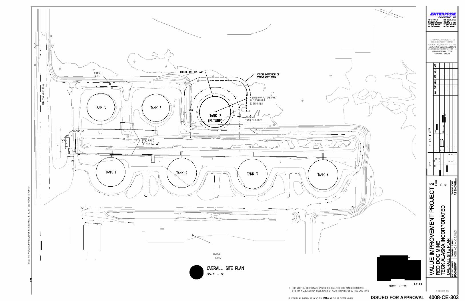
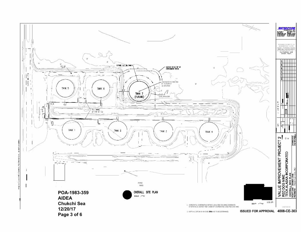
" CE NTE R OF FUTURE TANK
IN: 5,130,061.0 :E: 605,058.8
E DGE OF TA NK SHOULDER
I 1
..,_
Ii "' I lil ":..::>..' II! _ iIIi! 5..l Q
.. <(
8'"' "$' 15
ID [.)
"' "' ... "' "'
U"'I fil
I ! G !ii!
ili i l l
j
I :
I : :
--- =
STORAGE YAR D
...
OVERALL SITE PLAN E
SCALE: ,• = 50'
!
1. HORIZONTAL COORDINATE S YSITM IS LOCAL RED DOG MINE COORDINATE S Y S ITM IN U.S. SURVEY FEET. E!ASIS OF COORDINATES US ED RED DOG t.l lNE
SHNUMBER
2. V E RTir.A L DATUM IS NA VO B B. lBMs A A E TO B E DETERMINED. ISSUED FOR APPROVAL 4008-CE-303
I

£ L... ORI GI NAL SH E SlE; :Q:U:A :L:s2:':Z:" x,34:"., J,; ;; ;; ;; ;;; ;; ;; ;; ;;; ;; ; ;; ;; ;; ;;; ;;; ;;; ;; ;; ;;! ;; ;; ;; ;; ; ;; ;;! ,I
SCALE: 1• = 2 - -0'
re
i5
THISDRAWING ISA CONCEl'Tl.IAL DESIGN ONLY TODEl'lllE T!IE
MINIMUM RE QUREME NTS.TH EFINAL DESIGN illW.l. TAKE INTO ACCOUNT AU.CONSIDERATI ONSTOPRO'llDE A
F\JLLY F\JNCTIONAL, COClE COW'UANT FACILITY.
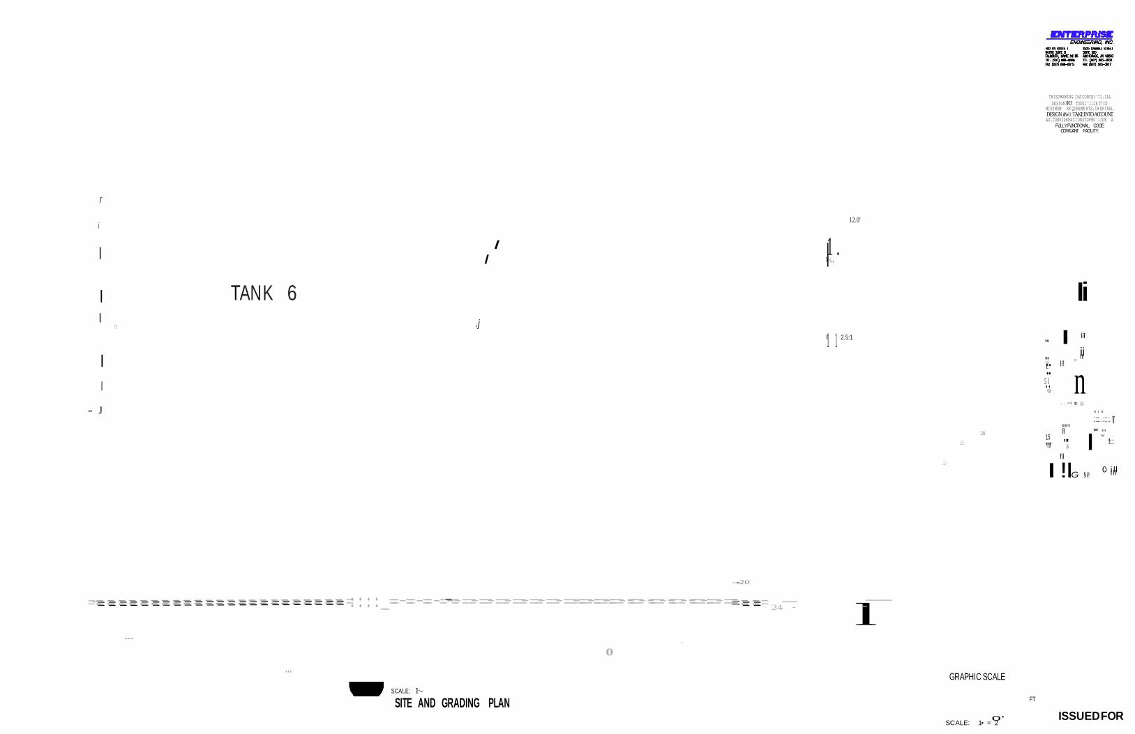
r
i
I I I
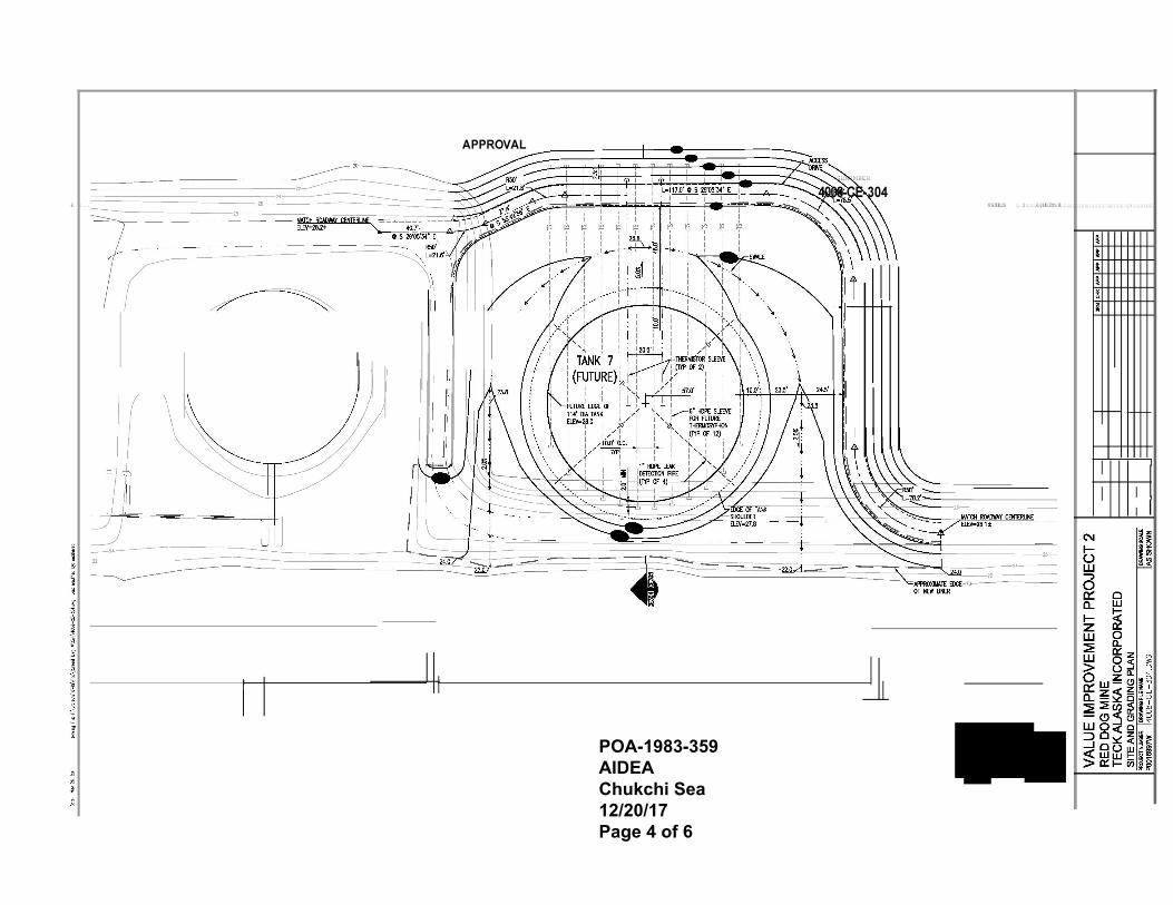
I TAN K 6
1 .
1-:,, I
12.0'
Ii I .j
..,_ I 2.5:1 1 1 "' I lil
I ":..::>..' II!
5.l. Q
_ iIIi!
n - J
20 15
22 "U'I
.. <(
8'"' "$'
fil
ID [.)
.":::':. ".::::. .i.j. "' "' I w !::
I !IG !ii! 0 ii llll
----------20
=-=== === === === === === === === === === === === === === === === === === === === === === === =::::_==-==-==-=---=-==-==-==-==-==-==-==-===-===-===--===--===--===--===-===-==== === ====
--- -
0
24--
---- l--------------
... GRAPHIC SCALE
SCALE: 1·- -- - - SITE AND GRADING PLAN FT
ISSUED FOR
I
24
APPROVAL
SHNUMBER
4008-CE-304 £ L.. ORIGIN;A;L,:S::H :;,: .S; ::; ;:;,E:;:Q::U:A:L::S:2;:2:'x, 3.4:;,l,;;;; ;;;;; ;;;;; ;;;;; ;;;;; ;;;;;; ;;;;; ;;;;o :; ;;;;;; ;;;;; ;J
- - - SCAL
I
1·-0·
I - -I 2
E: 1/2" -
I
i5
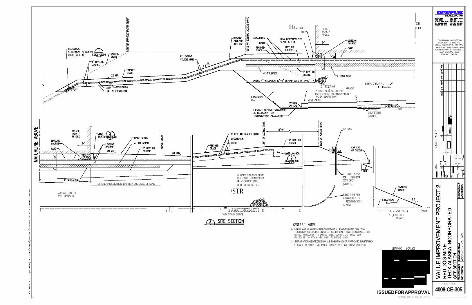
ffi. LINER SKIRT
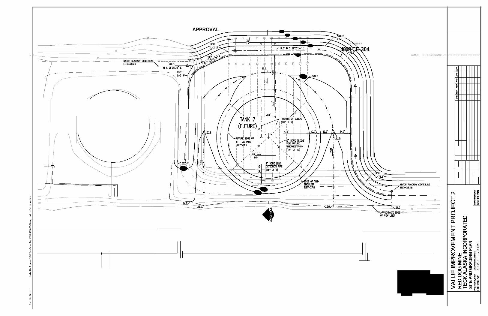
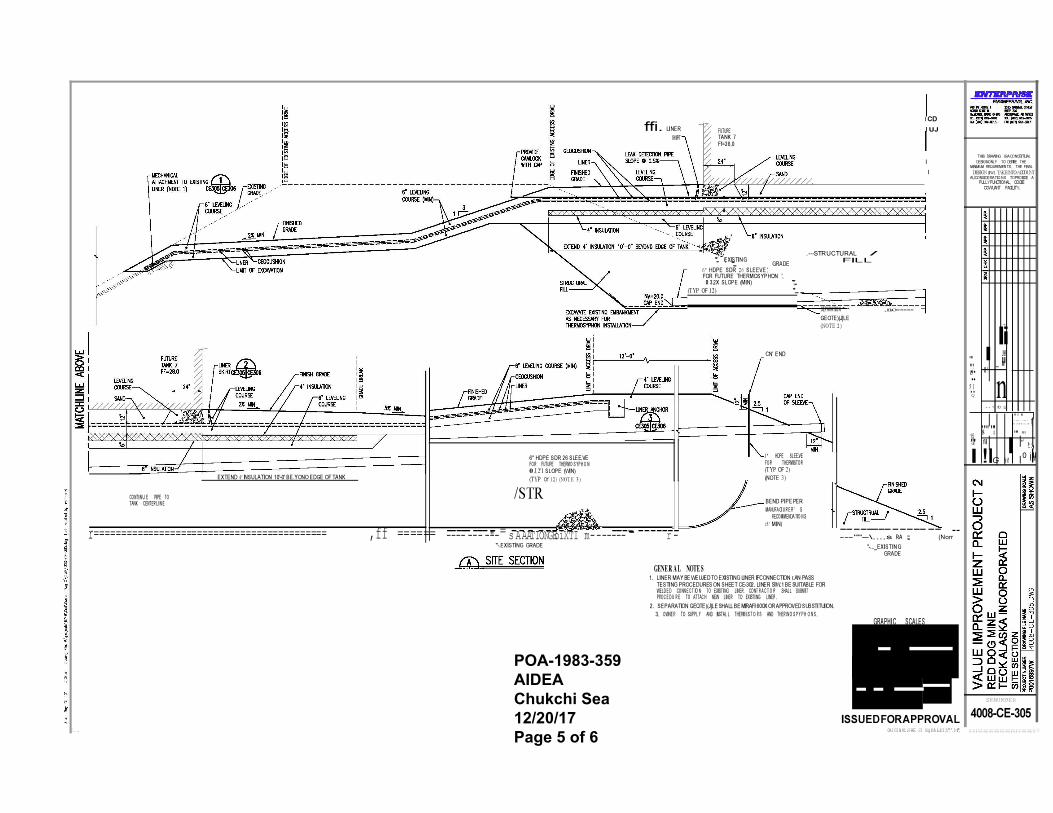
FUTURE TANK 7 Ff=28.0
I CD I UJ
I THIS DRAWING ISA CONCEl'Tl.IAL
I DESIGNONLY TO DEl'lllE THE MINIMUM REQUREMENTS. THE FINAL
I DESIGN illW.l. TAKE INTO ACCOUNT AU.CONSIDERATIO NS TOPRO'llDE A
F\JLLY F\JNCTIONAL, COClE COW'UANT FACILITY.
', (EXISTIN G ', GRADE 6" HDPE SDR 26 SLEEVE ', FOR FUTURE THERMOSYPHON ',
0 3.2X SLOPE (MIN) '',
.---STRUCTURAL /
FILL
(TYP OF 12) ',, CN' END
SEPARATION ,no----- GEOTE)(J]LE (NOT E 2)
..,,
Ii "' I lil
":..::>..' II!
5.l. Q
_ iIIi!
n .. <( ID [.)
8'"' "$' 15
.":::':. ".::::. .i.j. "' "'
"U'I fil I w !::
CONTI N U E PIPE TO
EXTEND 4' I NSULATION 10'-0' BE.YONO EDGE OF TANK
6" HDPE SDR 26 SLEE.VE FOR FUTURE THERMO S YP H O N 0 J.2'1 SLOPE (WIN) (TYP Of 12) (NOT E 3)
/STR
1 " HDPE SLEE.VE FOR THERMISTOR (TYP OF 2) (NOTE 3)
I !IG !ii! 0 ii llll
TANK CENTER LI N E BEND PIPE PER MANUFA Cl U R E R ' S
RECOMMENDA TIO N S
r=========================================== ,ff ====== -------------------"-= s-A-AA-TI-ON-G-Eo-iX-TI m- ------------ -----r--- "'-.EXISTING GRADE
GENE R A L NOTE S 1. LINER MAY BE WEUJED TO EXISTING LINER IF CONNECTION r.AN PASS
TESTING PROCEDURES ON SHEET CE-302. LINER SIW.1 BE SUITABLE FOR WELD E D CONN E C T IO N TO EXISTI NG LINER. CONT R A C T O R SHALL SUBMI T PROC E D U R E TO ATTAC H NEW LINER TO EXISTI NG LINER .
2. SEPARATION GEQTE)(J]LE SHALL BE MIRAFI 600X OR APPROVED SUBSTlTUllON. 3. OWNE R TO SUPPL Y AND INSTAL L THERM I S T O R S AND THER W O S P Y P H O N S .
--------------- -- ---""--\....s RA ; (Norr
"-..._EXIST IN G GRADE
GRAPHI C SCALES
- - - - --
ISSUED FOR APPROVAL L. ORI GI N AL SHE Sl E:Q:U: A: :L:S: 2 2;",'.3: :4",
SHNUMBER
4008-CE-305 ;;;;;;;;;;;;;;;;;;;;;;;;;;;;;;;;;;;;;;;;;;:;;;;;;;;;;;=.I
(5 ' MIN)

- - -
I
I - -I 2
i.5.
I
3/B' DIA STAINLESS
FINIS H G RA D E
1" DIA HOPE LfA K DETECTIO N
THISDRAWING ISA CONCEl'Tl.IAL DESIGN ONLY TO DEl'lllE THE
MINIMUM REQUREMENTS. THEFINAL DESIGN illW.l. TAKE INTO ACCOUNT AU.CONSIDE RA TI O NSTOPRO'llDE A
F\JLLY F\JNCTIONAL, COClE COW'UANT FACILITY.
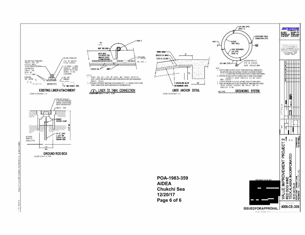
3/8" DIA FULlY THREADED STAINL E S S STEEL STUD 0 12" O.C. WELD TO BOTTOM 8ATTEN BAR CONTINUOUS
STEEL NUT W/W A S H E R AT STUD LOCAT IO N S
1/4" THICK x 2" WIDE CONTIN UO U S NEOPRE N E
============ =====::::::=====\ PIPE (NOTE 1)
NOTES:
GROUND ROD B OX (TYP OF 2Jffi (NOTE 3)CB
STAINL B S STEEL BATTEN BAR 3/16" x 2" WIDE EXISTING LINER MATERIAL
GASKET W/ 1/2" DIA OPENI N G S AT STUD LOCATIONS
NEW LINER MAltRIAL
NOT E S: 1. PROVI D E SOLID SOR 1 1 HOPE PIPE OUTSI D E LINER. PROVI D E D PERFO R A T E D
SOR 11 HOPE PIPE WITHIN LINER. WRAP PERFORATED PIPE WITH NONWOVEN
1. COPPER WIRE LOCATED ABOVE TANK LINER SHALL BE INSUIATED. INSUIATION SHALL BE SUITABLE FOR WET LOCATIONS THAT MAY HAVE FUEl EXPOSURE. PRO'YlDE BOOT SEAL AT LINER PENETRAllON.
2. PRO'YlDE fir AWG COPPER CONNECTION TO TANK 6 GROUNDING - COOR DI N A T E GROU N D CONN E C T I O N W ITH TANK CONTR O L
WIRIN G L.OCAT IO N . f-w, """'i"""'----t
EXISTING LINER ATIACHMENT
CEJ05 C£308 SCALE: N1S
PRECAST BOX SET FLUSH WITH FINISHED GRADE. COVER SHALL
DRAI N A G E GEOrnmLE . 2. PROVIDE SUFFlCIENT LINER AND GEOCUSHION (18" NJ:J'/E GRADE) FOR FUTURE
TANK CONNECTION. BURY LINER AND GEOCUSHKlN IN PLACE.
LINER ANCHOR DETAIL CEJ05 C£308 SCALE: N1S
3. LOCATE GROUND ROD B OXES OUTSIDE EDGE OF TANK LINER. 4. TANK GROUNDING WG TO BE PROVIDED BY TANK MANUFACTURER.
PRO'Yl D E SUFFI C I E N T GROU N D I N G WIRE THRO U G H LINER FOR CONN E C T I O N TO TANK.
cs GROUNDING SYSTEM
..,,
Ii I lil
READ "GROUND ROD"
FINIS H E D GRADE "":.::>.''
5.l. Q
II! _ iIIi!
n .. <(
8'"' "$' 15
ID [.)
"' " ...
"' "' U"'I fil
I 4/0 AWG BARE CU CABLE (TYP)
1·-0· MIN
GROUND ROD BOX C£.306 C£308 SCAIE : N1S
! G !ii! ili i l l
GRAPHIC SCALES
- - - - --"
SHNUMBER
ISSUED FOR APPROVAL 4008-CE-306 £ l. . . -O RI G IN A L SH E Sl E;Q:U:A:L:s: 22 " "3 4". . &; ;;; ; ;; ; ;;; ;; ; ;; ;;; ;; ; ; ;; ;; ; ;; ; ;; ;;; ; ;; ; !;; ;; ; ;; ;;; ;; ; !, I
I
P:\Drafting\WorkFiles\22000-22499\22298\22298-01r01.dwg, 5252017 7:58:26 AM, 1:1
VALUE IMPROVEMENT PROJECT 2 M A NA GE M E NT RE V IS IONS & A DDE NDUM S
RED DOG MINE TECK ALASKA INCORPORATED 4008-CE-307
DE S IGNE D DRAWN
CHE CK E D
A P P ROV E D
LA S T E DIT
J.F.K . R.H.
E.S.
J.F.K .
52517
DA TE REMARKS A 3-28-2017 IS S UE D FOR RE VIEW B 4-17-2017 IS S UE D FOR A PPROV AL C 5-26-2017 RE IS S UE D FOR A PPROVAL
DRN CHK APP APP APP APP
P ROJE CT NUM B E R
P0016997W DRA WING FILE NA M E
22298-01R01.DWG DRA WING S CA LE
AS SHOWN P LOT DA TE
S UB M ITTA L
52517
05-25-2017
“ ”
THIS DRAW
ING IS A CONCEPTUAL DESIGN ONLY TO DEFINE THE
MINIM
UM REQUIREMENTS. THE FINAL
DESIGN SHALL TAKE INTO ACCOUNT ALL CONSIDERATIONS TO PROVIDE A
FULLY FUNCTIONAL, CODE COM
PLIANT FACILITY.
SHEET NUMBER
4008-CE-307 REV C
ISSUED FOR APPRO
VAL ORIGINAL SHEET SIZE EQUALS 22"x34"
PROJECT #
DRAWN BY: ZB
CHECKEDBY: VR
DATE: 12/20/17
SCALE: 1 " = 208 '
R
P
POA-1983-359AIDEAChukchi Sea12/20/17Page 1 of 6
204
u
POA-1983-359AIDEAChukchi Sea12/20/17Page 2 of 6
50'
lil
POA-1983-359AIDEAChukchi Sea12/20/17Page 3 of 6
POA-1983-359AIDEAChukchi Sea12/20/17Page 4 of 6
1/2"
I
I
I
',
.---STRUCTURAL
lil
(Norr
POA-1983-359AIDEAChukchi Sea12/20/17Page 5 of 6
1/4"
4/0
POA-1983-359AIDEAChukchi Sea12/20/17Page 6 of 6