phulpur unit i f f c o - iitk - indian institute of ...home.iitk.ac.in/~katheria/reforming.pdf ·...
TRANSCRIPT

INDIAN FAREMRS FERTILISER COOPERATIVE LIMITED PHULPUR UNIT
1
I F F C O
12/8/2011 Steam Reforming- Presented by Sanjay Katheria 502237

Outline of the Presentation
2 12/8/2011 Steam Reforming- Presented by Sanjay Katheria 502237
General Chemistry of Steam Reforming
Catalyst
Operating Conditions
Pre Reformer
Primary Reformer
Secondary Reformer

Source & References
Steam reforming of natural gas is the most common method of producing commercial bulk hydrogen as well as the hydrogen used in the industrial synthesis of ammonia.
Steam reforming can be described by the reversible reaction(s)
CnHm + nH2O nCO + (n + m/2 ) H2 CH4 + H2O CO + 3H2 [ΔH = +206 kJ mol-1] CO + H2O CO2 + H2 [ΔH = -41 kJ mol-1] CH4 + 2H2O CO2 + 4H2 [ΔH = +165 kJ mol-1]
Strongly endothermic reaction
General Chemistry Introduction
Conclusion
Steam Reformers
12/8/2011 3 Steam Reforming- Presented by Sanjay Katheria 502237

Rhodium, Nickel, Palladium, Platinum and combinations of these metals.
Nickel based catalysts widely used, although nickel-based catalysts require a high reaction temperature and an excess amount of steam to prevent coke deposition on the catalyst surface.
Alumina, Zirconium dioxide and Magnesium Oxide etc. as catalysts support.
Low and high alkali catalysts
Catalysts
12/8/2011 4 Steam Reforming- Presented by Sanjay Katheria 502237
Source & References
Introduction
Conclusion
Steam Reformers

Many poisons affect reforming catalysts including sulphur, metals, halides and phosphates. Sulphur is a particular problem because:
- Nickel is a very good sulphur adsorbent - Only a small amount of sulphur can cause problems , sulphur can totally deactivate a reforming catalyst
12/8/2011 5 Steam Reforming- Presented by Sanjay Katheria 502237
Source & References
Introduction
Conclusion
Steam Reformers
Catalysts
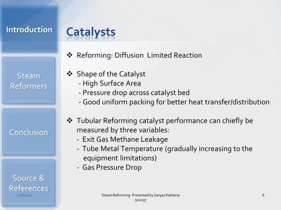
Reforming: Diffusion Limited Reaction
Shape of the Catalyst - High Surface Area - Pressure drop across catalyst bed - Good uniform packing for better heat transfer/distribution
Tubular Reforming catalyst performance can chiefly be
measured by three variables: - Exit Gas Methane Leakage - Tube Metal Temperature (gradually increasing to the
equipment limitations) - Gas Pressure Drop
12/8/2011 6 Steam Reforming- Presented by Sanjay Katheria 502237
Catalysts
Source & References
Introduction
Conclusion
Steam Reformers

Combination of a relatively small catalyst size in the top and a larger size in the lower part of the tubes.
Carbon formation over catalyst surface – 2 CO C + CO2 CH4 ➔ C + 2 H2 CO + H2 ➔ C + H2O
– Low S/C ratio – High C/H ratio and relative low temperature – Low temperature conditions at feed inlet (upper part of catalysts tubes).
Catalysts
12/8/2011 7 Steam Reforming- Presented by Sanjay Katheria 502237
Source: HTAS Catalyst Manual Source &
References
Introduction
Conclusion
Steam Reformers

Carbon to Hydrogen (mass)ratio of feed -(C/H ratio)
Steam to Carbon (molar)ratio - (S/C ratio)
Temperature
Pressure – Higher temperatures result in less methane and more
carbon monoxide. – Surplus of steam favors both low methane and low carbon
monoxide. – High pressure increases the methane content.
Operating Conditions
12/8/2011 8 Steam Reforming- Presented by Sanjay Katheria 502237
Source & References
Introduction
Conclusion
Steam Reformers

Operating Conditions
12/8/2011 9 Steam Reforming- Presented by Sanjay Katheria 502237
%CH4 (dry)
%CH4 (dry)
Source: HTAS Catalyst Manual
Source & References
Introduction
Conclusion
Steam Reformers

Pre Reformer Primary Reformer Secondary Reformer
Type of furnaces: - Side fired furnace - Vertical fired multi row furnace
Comparison of Side Fired and Vertical Fired Furnace
– Mode of heat transfer – Temperature distribution – Size – Heat loss – Efficiency
Steam Reformers
12/8/2011 10 Steam Reforming- Presented by Sanjay Katheria 502237
Source & References
Introduction
Conclusion
Steam Reformers

11 12/8/2011 Steam Reforming- Presented by Sanjay Katheria 502237
Adiabatic Pre Reformer
Main purpose of primary reformer to convert higher hydrocarbons in to methane.
To achieve the reaction temperature, feed is heated in mixed feed coil of convection section of primary reformer.
Two Catalyst Beds
Source & References
Introduction
Conclusion
Steam Reformers
Process Gas Inlet
Process Gas Outlet

12/8/2011 12 Steam Reforming- Presented by Sanjay Katheria 502237
Reactions involved: CnH2n+2
+ 2H2O Cn -1H2n + CO2 + 3H2 - Heat CH4
+ 2H2O ➔ CO2 + 3H2 - Heat CO2 + H2 ➔ CO + H2O - Heat Net effect is slight increase in temperature (12oC) – Performance Indicator
12 Temperature Indicators: 7 in Top Bed and 5 in Lower Bed
Temperature Profile: indication of catalyst deactivation
Reactions in Pre Reformer…
Source & References
Introduction
Conclusion
Steam Reformers

12/8/2011 13 Steam Reforming- Presented by Sanjay Katheria 502237
Inlet Outlet
Temperature 490oC 505 oC
Pressure 36.8 kg/cm2 35.7 kg/cm2
Composition(in % Dry basis)
CH4 0.35 50.80
H2 36.59 24.45
N2 12.20 3.02
Ar 0.15 0.04
CO - 0.54
CO2 0.46 20.15
C3 + 50.25 -
Process Gas Flow Rate(Dry) 18305 Nm3 /hr
Total Gas Flow Rate 192805 Nm3 /hr
Operating Conditions…
Source & References
Introduction
Conclusion
Steam Reformers

12/8/2011 14
Steam Reforming- Presented by Sanjay Katheria 502237
Operating Conditions
Minimum Maximum Normal
Temperature 0C 380 600 490
Pressure kg/cm2 34 46 39
Reactor Data
ID(mm) Height(mm) Volume(m3)
Bed # 1 2750 2350 13.90
Bed # 2 2750 1450 9.50
Size and Shape: 11x5 mm ( cylindrical with 7 holes)
Ni 25%
Al2O3 11%
MgO balanced
Pre Ref0rmer Catalyst
Source & References
Introduction
Conclusion
Steam Reformers

12/8/2011 15 Steam Reforming- Presented by Sanjay Katheria 502237
Primary Reformer - Radiant Section - Convection Section
144 vertical mounted high
alloy steel(288 tubes in total).
576 forced draught burners in 6 rows.
8 Coils in Convection Section.
Primary Ref0rmer
Source & References
Introduction
Conclusion
Steam Reformers
Process Gas Inlet
Process Gas Outlet

12/8/2011 16 Steam Reforming- Presented by Sanjay Katheria 502237
Inlet Outlet
Temperature 500oC 773 oC
Pressure 35.7 kg/cm2 33.4 kg/cm2
Composition(in % Dry basis)
CH4 94.03 13.0
H2 3.48 67.64
N2 1.64 0.55
Ar 0.01 0.01
CO - 8.29
CO2 0.15 10.51
C2H6 0.66 -
C3H8 0.03 -
Contd..
Source & References
Introduction
Conclusion
Steam Reformers

Catalyst Tube I.D. / O.D. – 129/150 mm
Catalyst tube length – 12090 mm
Catalyst bed height in tubes -11,370 mm
Tube Material – 25Cr 35Ni Nb Ti
Maximum tube wall temperature – 905 0 C
Actual design temperature – 872.5 0 C
Current tube wall temperature – 875 0 C
12/8/2011 17 Steam Reforming- Presented by Sanjay Katheria 502237
Catalyst Tubes
Source & References
Introduction
Conclusion
Steam Reformers

12/8/2011 18 Steam Reforming- Presented by Sanjay Katheria 502237
Primary Reformer Burner
Combustion Air
RLNG Fuel
Combustion Air Source & References
Introduction
Conclusion
Steam Reformers

12/8/2011 19 Steam Reforming- Presented by Sanjay Katheria 502237
Burner Specification
Type: Radol MKILP1 Combustion Air: Forced Draught Combustion Air Temperature Designed: 280 oC Designed Excess Air: 10% Normal Excess Air: 5% Designed Air Pressure: 200 mmWg Maximum Furnace Draught: -15 mmWg Design Gas Pressure(Fuel): 1kg/cm2g Burner Duty, Maximum: 463,000 KCal/hr Burner Duty, Normal: 370,500 KCal/hr Burner Duty, Minimum: 92,500 Kcal/hr
• Burner Duties given above include the preheating of fuel
of combustion air. Source & References
Introduction
Conclusion
Steam Reformers

12/8/2011 20 Steam Reforming- Presented by Sanjay Katheria 502237
Catalyst Shape: Ribbed Ring
Top Half Bottom Half
Ni 25 15-20
MgO Balance 20-25
Al2O3 11 55-60
SiO2 - <100 ppm
S - <2000 ppm
Cl- <50 ppm -
Bulk Density 0.9-1.0 kg/lt 0.9-1.0 kg/lt
Make HTAS Denmark HTAS Denmark
Type RKNR R-67-7H
Volume 21.4 m3 21.4 m3
Radial Crushing Strength 15-20 kg/cm 30 kg/cm
Catalyst
Source & References
Introduction
Conclusion
Steam Reformers

12/8/2011 21 Steam Reforming- Presented by Sanjay Katheria 502237
Secondary Reformers
Reformer Outlet
Mixing and combustion of reformed process gas with process air.
- Mixing of N2 - Utilization of O2 by combustion - Temperature raised to 1200 o C
Amount of air(nitrogen) addition
depend on desired N2 to H2 ratio.
Thermo indicative coating.
Normal skin temperature 160 o C (designed 300o C)
Feed Gas
Process Air
Source & References
Introduction
Conclusion
Steam Reformers

12/8/2011 22 Steam Reforming- Presented by Sanjay Katheria 502237
Inlet Outlet
Temperature 773 959
Pressure 33.4 32.8
Air entering in secondary reformer at temperature 5550 C
and pressure 34 kg/cm2
Composition(in % Dry basis)
CH4 13 0.45
H2 67.64 55.92
N2 0.55 23.29
Ar 0.01 0.28
CO 8.29 12.41
CO2 10.51 7.65
Operating Conditions
Source & References
Introduction
Conclusion
Steam Reformers

12/8/2011 23 Steam Reforming- Presented by Sanjay Katheria 502237
Size and Shape: 11x5 mm (Ribbed Rings)
Ni 8-10%
Al2O3 87-90%
SiO2 <0.05 %
S < 0.05%
Make UCI, USA
Type C-14-02-RR
Volume 39 m3
Size 16mm x 16mm x 6mm
Shape Ribbed Rings
Bulk Density 1.1 + .1 kg/lt
Catalyst
Source & References
Introduction
Conclusion
Steam Reformers

Shape of the catalyst Ni based Catalyst Vertical and side fired furnaces Ni content of catalyst influenced by process gas
composition and reaction temperature CO and CO2 content in process gas after primary
reformer and secondary reformer
12/8/2011 24 Steam Reforming- Presented by Sanjay Katheria 502237
Source & References
Introduction
Conclusion
Steam Reformers
Conclusion

Ammonia II Training Manual HTAS Manual Volume I and Volume VI Fertilizer Science and Technology Series, Volume II : Ammonia
Part I, Slack & James HTAS Reforming Catalyst Manual http://resources.schoolscience.co.uk/johnsonmatthey/page17.ht
m http://www.chemengservices.com/tech35.html Hydrogen production by steam reforming of LNG over Ni/Al2O3-
ZrO2 catalysts: Effect of ZrO2 and preparation method of Al2O3-ZrO2 by Jeong Gil Seo, Min Hye Youn, Sunyoung Park, Joohyung Lee, Sang Hee Lee, Howon Lee and In Kyu Song
12/8/2011 25 Steam Reforming- Presented by Sanjay Katheria 502237
Source & References
Source & References
Introduction
Conclusion
Steam Reformers

Thank you..
26
12/8/2011
Steam Reforming- Presented by Sanjay Katheria 502237