rsv4 2017 mm race kit - af1racing.com · control units are directly managed by the official aprilia...
TRANSCRIPT
RSV4 2017 MM RACE KIT (V2.1)
INSTRUCTIONS FOR CONVERTING APRILIA RSV4 FROM STREET LEGAL
CONFIGURATION TO RACING VERSION FOR TRACK USE, WITH STANDARD OR
MM RACE ECU
INTRODUCTION:
• The material, information and procedures described in this manual are solely for usage of the vehicle in
motorsports competitions on circuits closed to traffic. Usage on public roads is strictly prohibited.
• The operations can be described in a generic way, as it is deduced that the technician knows in detail
how to act mechanically on each component.
• This material may be installed by specialized motorcycle mechanics only.
• Specific instruments may be necessary for the installation of certain components.
• The manufacturer reserves the right to modify the technical specifications, components and other
information described and contained in this catalogue without prior notification.
WARRANTY:
• None of these components are covered by warranty. The manufacturer cannot be held responsible for
any problems, damage or injury caused by using these parts.
DESCRIPTION OF MANUAL:
The following manual illustrates the operations and modifications necessary to transform the vehicle from the
standard production configuration to a configuration for motorsports use on closed race circuits.
The operations for modifying and installing parts are described as follows. Follow the directions and procedures
contained herein, which illustrate the operations for installing and modifying parts, exactly as given. Some of the
individual operations described offer a number of different modification options, where the user is required to
choose the option applied.
Work and suggestions for motorcycle conversion, in racing version.
1- Mounting and Specifications of the MM Race ECU.
2- Removing the side stand.
3- Removing the ignition switch assembly.
4- Racing dashboard without immobilizer.
5- Elimination of gasoline vapor recovery system.
6- Mounting the voltage regulator on the chassis.
7- Reversing “racing” gear.
8- Removing the thermostat and installing the simplified water hose kit.
9- Elimination of the secondary air circuit.
10- ABS system removal.
11- Suggested SET UP for the bike.
12- Mechanical adjustment of engine brake intervention.
NOTE - Some of these changes vary and can be performed if combined with other operations.
Before you start work, you need to understand what changes you want to do to the bike, because for some
operations, you need to take the engine out of the vehicle.
The most complex operations to perform and which require the removal of the motor are: the removal of the
ABS system pipes and the removal of the secondary air circuit from the engine.
1 - MM RACE CONTROL UNIT FOR RACETRACK USE
Aprilia Racing provides a control unit specifically meant for customers who use their RSV4 bike with a racetrack
configuration. However, we should note the differences compared to control units that can be configured, from
the official Aprilia network. The standard bike is sold on the basis of applicable laws and type approval for each
individual nation, with the mapping required for road use in that nation. Should a customer purchase a
complete full titanium or slip-on Akrapovic exhaust system, the dealership will install the injection and
advancement map designed for the racing exhaust system in the ECU. Through its official network, Aprilia also
sells an original control unit, which has already been programmed for racing exhaust systems, for customers
who have purchased an aftermarket exhaust system and cannot received the map from the dealer. These
control units are directly managed by the official Aprilia network, and are suitable for road use.
For customers who only use their bike on the racetrack, Aprilia Racing provides an ECU specifically designed
for such use, which is different from the one managed by the official Aprilia network and may only be
purchased from Aprilia Racing. Any updates to the Aprilia Racing ECU are exclusively provided by Aprilia
Racing.
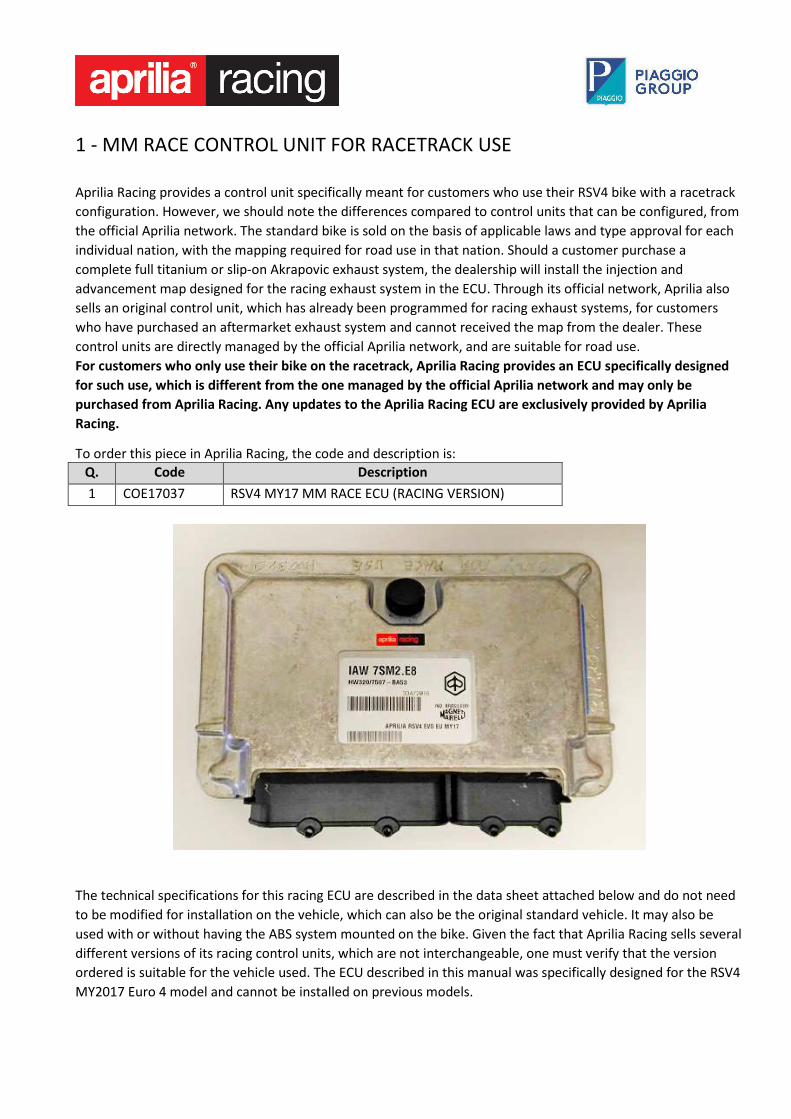
To order this piece in Aprilia Racing, the code and description is:
Q. Code Description
1 COE17037 RSV4 MY17 MM RACE ECU (RACING VERSION)
The technical specifications for this racing ECU are described in the data sheet attached below and do not need
to be modified for installation on the vehicle, which can also be the original standard vehicle. It may also be
used with or without having the ABS system mounted on the bike. Given the fact that Aprilia Racing sells several
different versions of its racing control units, which are not interchangeable, one must verify that the version
ordered is suitable for the vehicle used. The ECU described in this manual was specifically designed for the RSV4
MY2017 Euro 4 model and cannot be installed on previous models.
ECU Marelli Racing RSV4 RR/LE MY17, code: COE17037 V1.0
ECU configuration: RH1701 - xx (RSV4 RR/LE MY17 bike – HW320)
Aprilia Racing has developed a dedicated ECU for the RSV4 RR/LE MY17 for track use. The ignition advance and
injection maps are the same maps used for the Akrapovic exhaust system, which are available from the official
Aprilia network. The electronic management system parameters determining the activation thresholds of the
vehicle control systems, however have been completely recalibrated for use specifically on a closed race circuit.
These new calibrations allow extreme banking angles without triggering an invasive response from the control
systems, which may still be set from the switchgear on the handlebar. The reduced engine braking effect allows
faster, smoother braking. The Marelli Racing ECU has been specifically reprogrammed for this application, and
the new map differs from the standard production one, as follows:
• Injection and ignition advance maps for complete Akrapovic exhaust system
• Configured for slick tires use (type Pirelli SC1)
• Management disabled of exhaust butterfly valve, oxygen sensor and secondary air system.
• Suitable for interfacing with the Aprilia APP V4-MP. To use these functions, You have to connect to the
system, a smartphone with the dedicated app
• Immobilizer disabled (in ECU). � NOTE – the instrument cluster must also be replaced in order to remove the ignition switch assembly and the physical immobilizer
system.
Functional differences relative to standard map:
� Optimised and even less invasive TCS. Most significant benefits stem from reduced torque limiting at
extreme bank angles and during rapid changes in direction.
� Wheelie control system with optimised torque limiting action.
� Reduced engine brake effect in general, and in low gears in particular.
� All engine maps are completely unrestricted (full power) and specific for racing exhaust systems.
� Also usable with ABS. In any case, the ABS control unit must remain connected to the electrical wiring
and in the original position.
� The three maps in the ECU are configured as follows:
S – Map with extremely direct throttle response.
T – Map with softer, more progressively controllable response at initial throttle aperture. Engine braking effect
is generally lower.
R – Same as map T, but with even less engine braking effect at mid to high engine speeds.
We recommend starting with the T or R map, with TCS set to level 4
NOTE:
1. This ECU must be used together with the standard clutch control switch. The ECU will not function correctly if this switch is
removed.
2. This ECU cannot be used on previous versions of the RSV4.
3. We recommend starting with a high TCS level when using for the first time, and then trying gradually lower settings.
4. Important - Use only spark plugs with type and brand, as described in the use and maintenance booklet of the bike.
IMPORTANT NOTES:
• This ECU was designed for use in motorsports competitions on circuits closed to traffic. For this reason, use on public roads is
strictly prohibited.
• This ECU must be installed by expert personnel with official palm-held instrumentation for configuration of the bike's
parameters.
• This component is not covered by warranty and therefore the manufacturer cannot be held responsible for any problems or
damage caused.
• Always remember that making modifications to the electronics parameters may cause serious consequences for the bike and
the rider.
2 – REMOVING THE SIDE STAND
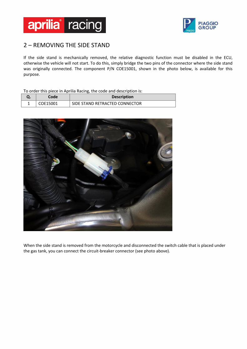
If the side stand is mechanically removed, the relative diagnostic function must be disabled in the ECU,
otherwise the vehicle will not start. To do this, simply bridge the two pins of the connector where the side stand
was originally connected. The component P/N COE15001, shown in the photo below, is available for this
purpose.
To order this piece in Aprilia Racing, the code and description is:
Q. Code Description
1 COE15001 SIDE STAND RETRACTED CONNECTOR
When the side stand is removed from the motorcycle and disconnected the switch cable that is placed under
the gas tank, you can connect the circuit-breaker connector (see photo above).
3 – REMOVING THE IGNITION SWITCH ASSEMBLY If the ignition switch assembly is removed, the switch COE15062 may installed on the same connector as the
ignition switch to switch the system on and off. This switch may be installed on the handlebar or, if preferred, in
another convenient location.
To order this piece in Aprilia Racing, the code and description is:
Q. Code Description
1 COE15062 CIRCUIT POWER SWITCH
IMPORTANT - Note the instructions given below when removing the ignition switch, depending on which of
the following two cases applies:
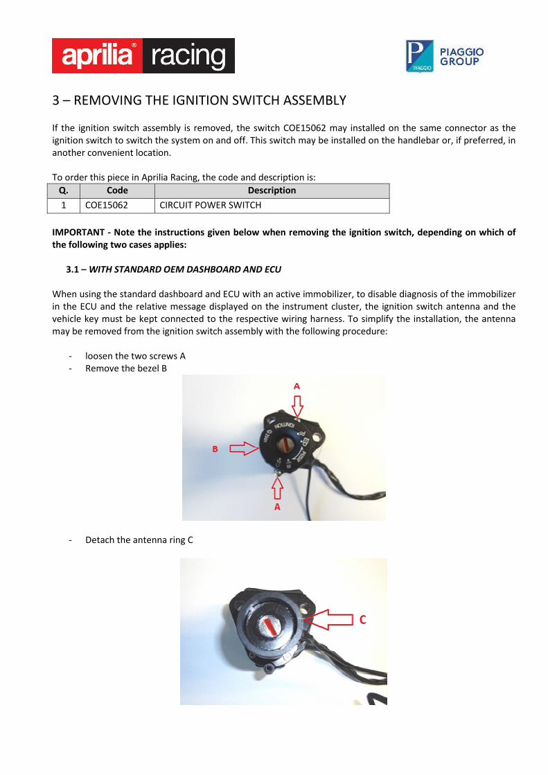
3.1 – WITH STANDARD OEM DASHBOARD AND ECU
When using the standard dashboard and ECU with an active immobilizer, to disable diagnosis of the immobilizer
in the ECU and the relative message displayed on the instrument cluster, the ignition switch antenna and the
vehicle key must be kept connected to the respective wiring harness. To simplify the installation, the antenna
may be removed from the ignition switch assembly with the following procedure:
- loosen the two screws A
- Remove the bezel B
- Detach the antenna ring C
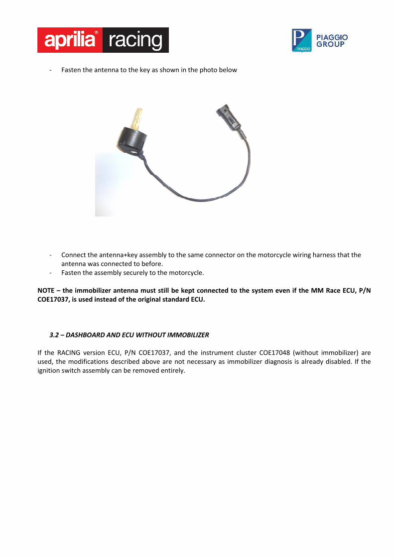
- Fasten the antenna to the key as shown in the photo below
- Connect the antenna+key assembly to the same connector on the motorcycle wiring harness that the
antenna was connected to before.
- Fasten the assembly securely to the motorcycle.
NOTE – the immobilizer antenna must still be kept connected to the system even if the MM Race ECU, P/N
COE17037, is used instead of the original standard ECU.
3.2 – DASHBOARD AND ECU WITHOUT IMMOBILIZER
If the RACING version ECU, P/N COE17037, and the instrument cluster COE17048 (without immobilizer) are
used, the modifications described above are not necessary as immobilizer diagnosis is already disabled. If the
ignition switch assembly can be removed entirely.
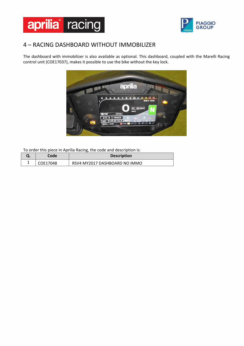
4 – RACING DASHBOARD WITHOUT IMMOBILIZER
The dashboard with immobilizer is also available as optional. This dashboard, coupled with the Marelli Racing
control unit (COE17037), makes it possible to use the bike without the key lock.
To order this piece in Aprilia Racing, the code and description is:
Q. Code Description
1 COE17048 RSV4 MY2017 DASHBOARD NO IMMO
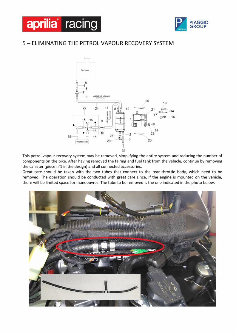
5 – ELIMINATING THE PETROL VAPOUR RECOVERY SYSTEM
This petrol vapour recovery system may be removed, simplifying the entire system and reducing the number of
components on the bike. After having removed the fairing and fuel tank from the vehicle, continue by removing
the canister (piece n°1 in the design) and all connected accessories.
Great care should be taken with the two tubes that connect to the rear throttle body, which need to be
removed. The operation should be conducted with great care since, if the engine is mounted on the vehicle,
there will be limited space for manoeuvres. The tube to be removed is the one indicated in the photo below.
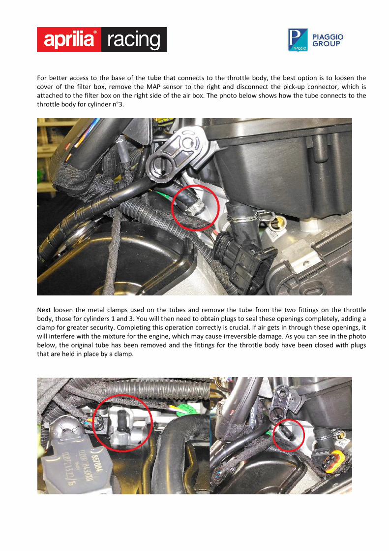
For better access to the base of the tube that connects to the throttle body, the best option is to loosen the
cover of the filter box, remove the MAP sensor to the right and disconnect the pick-up connector, which is
attached to the filter box on the right side of the air box. The photo below shows how the tube connects to the
throttle body for cylinder n°3.
Next loosen the metal clamps used on the tubes and remove the tube from the two fittings on the throttle
body, those for cylinders 1 and 3. You will then need to obtain plugs to seal these openings completely, adding a
clamp for greater security. Completing this operation correctly is crucial. If air gets in through these openings, it
will interfere with the mixture for the engine, which may cause irreversible damage. As you can see in the photo
below, the original tube has been removed and the fittings for the throttle body have been closed with plugs
that are held in place by a clamp.
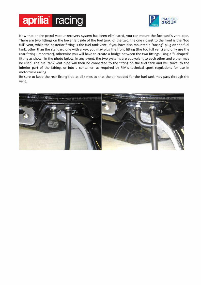
Now that entire petrol vapour recovery system has been eliminated, you can mount the fuel tank's vent pipe.
There are two fittings on the lower left side of the fuel tank, of the two, the one closest to the front is the "too
full" vent, while the posterior fitting is the fuel tank vent. If you have also mounted a "racing" plug on the fuel
tank, other than the standard one with a key, you may plug the front fitting (the too full vent) and only use the
rear fitting (important), otherwise you will have to create a bridge between the two fittings using a "T-shaped"
fitting as shown in the photo below. In any event, the two systems are equivalent to each other and either may
be used. The fuel tank vent pipe will then be connected to the fitting on the fuel tank and will travel to the
inferior part of the fairing, or into a container, as required by FIM's technical sport regulations for use in
motorcycle racing.
Be sure to keep the rear fitting free at all times so that the air needed for the fuel tank may pass through the
vent.
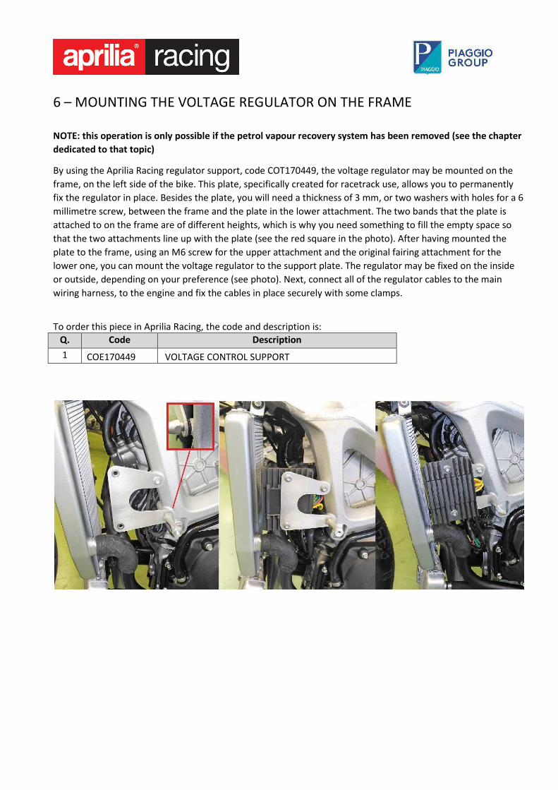
6 – MOUNTING THE VOLTAGE REGULATOR ON THE FRAME
NOTE: this operation is only possible if the petrol vapour recovery system has been removed (see the chapter
dedicated to that topic)
By using the Aprilia Racing regulator support, code COT170449, the voltage regulator may be mounted on the
frame, on the left side of the bike. This plate, specifically created for racetrack use, allows you to permanently
fix the regulator in place. Besides the plate, you will need a thickness of 3 mm, or two washers with holes for a 6
millimetre screw, between the frame and the plate in the lower attachment. The two bands that the plate is
attached to on the frame are of different heights, which is why you need something to fill the empty space so
that the two attachments line up with the plate (see the red square in the photo). After having mounted the
plate to the frame, using an M6 screw for the upper attachment and the original fairing attachment for the
lower one, you can mount the voltage regulator to the support plate. The regulator may be fixed on the inside
or outside, depending on your preference (see photo). Next, connect all of the regulator cables to the main
wiring harness, to the engine and fix the cables in place securely with some clamps.
To order this piece in Aprilia Racing, the code and description is:
Q. Code Description
1 COE170449 VOLTAGE CONTROL SUPPORT
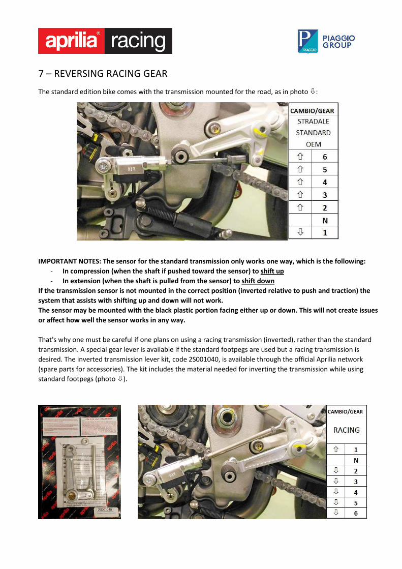
7 – REVERSING RACING GEAR
The standard edition bike comes with the transmission mounted for the road, as in photo �:
IMPORTANT NOTES: The sensor for the standard transmission only works one way, which is the following:
- In compression (when the shaft if pushed toward the sensor) to shift up
- In extension (when the shaft is pulled from the sensor) to shift down
If the transmission sensor is not mounted in the correct position (inverted relative to push and traction) the
system that assists with shifting up and down will not work.
The sensor may be mounted with the black plastic portion facing either up or down. This will not create issues
or affect how well the sensor works in any way.
That's why one must be careful if one plans on using a racing transmission (inverted), rather than the standard
transmission. A special gear lever is available if the standard footpegs are used but a racing transmission is
desired. The inverted transmission lever kit, code 2S001040, is available through the official Aprilia network
(spare parts for accessories). The kit includes the material needed for inverting the transmission while using
standard footpegs (photo �).
As you can see from the photo above, with the new gear lever mounted on the footpegs, the gear shaft
connecting to the sensor is now raised compared to the fulcrum of the pilot footpeg, this way the transmission
is reversed (racing), with the sensor still mounted in the correct position.
To order this piece from an aprilia dealer, the code and description is:
Q. Code Description
1 2S001040 RACING REVERSE GEAR KIT
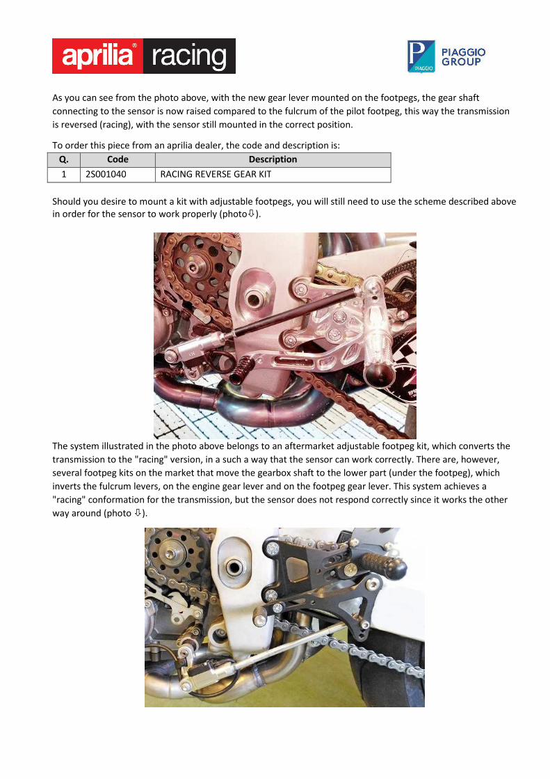
Should you desire to mount a kit with adjustable footpegs, you will still need to use the scheme described above
in order for the sensor to work properly (photo�).
The system illustrated in the photo above belongs to an aftermarket adjustable footpeg kit, which converts the
transmission to the "racing" version, in a such a way that the sensor can work correctly. There are, however,
several footpeg kits on the market that move the gearbox shaft to the lower part (under the footpeg), which
inverts the fulcrum levers, on the engine gear lever and on the footpeg gear lever. This system achieves a
"racing" conformation for the transmission, but the sensor does not respond correctly since it works the other
way around (photo �).
To use a footpeg kit like the one illustrated in the above photograph, the electric signal from the sensor will
need to be inverted. Aprilia Racing has created a tail fairing adapter for that purpose, inverting the electric signal
from the sensor. This tail fairing must be mounted between the connector for the transmission sensor and the
connector for the engine wiring harness. Through this operation the transmission sensor will be inverted and
will respond as follows:
- In compression (when the shaft if pushed toward the sensor) to shift down
- In extension (when the shaft is pulled from the sensor) to shift up
To order this piece in Aprilia Racing, the code and description is:
Q. Code Description
1 COE17074 CONNECTOR FOR GEAR SIGNAL INVERSION
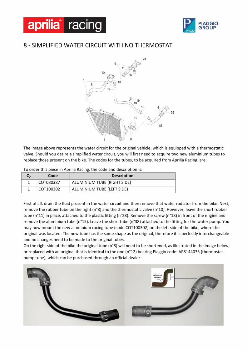
8 - SIMPLIFIED WATER CIRCUIT WITH NO THERMOSTAT
The image above represents the water circuit for the original vehicle, which is equipped with a thermostatic
valve. Should you desire a simplified water circuit, you will first need to acquire two new aluminium tubes to
replace those present on the bike. The codes for the tubes, to be acquired from Aprilia Racing, are:
To order this piece in Aprilia Racing, the code and description is:
Q. Code Description
1 COT080387 ALUMINIUM TUBE (RIGHT SIDE)
1 COT100302 ALUMINIUM TUBE (LEFT SIDE)
First of all, drain the fluid present in the water circuit and then remove that water radiator from the bike. Next,
remove the rubber tube on the right (n°8) and the thermostatic valve (n°10). However, leave the short rubber
tube (n°11) in place, attached to the plastic fitting (n°28). Remove the screw (n°18) in front of the engine and
remove the aluminium tube (n°15). Leave the short tube (n°38) attached to the fitting for the water pump. You
may now mount the new aluminium racing tube (code COT100302) on the left side of the bike, where the
original was located. The new tube has the same shape as the original, therefore it is perfectly interchangeable
and no changes need to be made to the original tubes.
On the right side of the bike the original tube (n°8) will need to be shortened, as illustrated in the image below,
or replaced with an original that is identical to the one (n°12) bearing Piaggio code: AP8144033 (thermostat-
pump tube), which can be purchased through an official dealer.
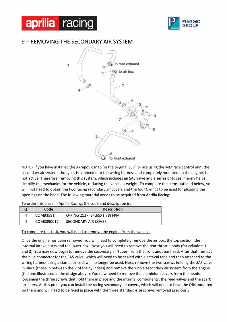
9 – REMOVING THE SECONDARY AIR SYSTEM
NOTE - If you have installed the Akrapovic map (in the original ECU) or are using the MM race control unit, the
secondary air system, though it is connected to the wiring harness and completely mounted on the engine, is
not active. Therefore, removing this system, which includes an SAS valve and a series of tubes, merely helps
simplify the mechanics for the vehicle, reducing the vehicle's weight. To complete the steps outlined below, you
will first need to obtain the two racing secondary air covers and the four O-rings to be used for plugging the
openings on the head. The following material needs to be acquired from Aprilia Racing:
To order this piece in Aprilia Racing, the code and description is:
Q. Code Description
4 COM93591 O-RING 2137 (34,65X1,78) FPM
2 COMS090017 SECONDARY AIR COVER
To complete this task, you will need to remove the engine from the vehicle.
Once the engine has been removed, you will need to completely remove the air box, the top section, the
internal intake ducts and the lower box. Next you will need to remove the rear throttle body (for cylinders 1
and 3). You may now begin to remove the secondary air tubes, from the front and rear head. After that, remove
the blue connector for the SAS valve, which will need to be sealed with electrical tape and then attached to the
wiring harness using a clamp, since it will no longer be used. Next, remove the two screws holding the SAS valve
in place (those in between the V of the cylinders) and remove the whole secondary air system from the engine
(the one illustrated in the design above). You now need to remove the aluminium covers from the heads,
loosening the three screws that hold them in place and the internal components: the reed valves and the spark
arresters. At this point you can install the racing secondary air covers, which will need to have the ORs mounted
on them and will need to be fixed in place with the three standard-size screws removed previously.
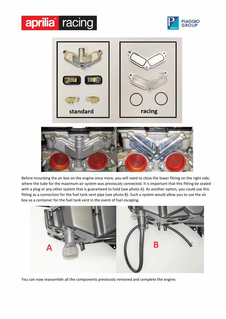
Before mounting the air box on the engine once more, you will need to close the lower fitting on the right side,
where the tube for the maximum air system was previously connected. It is important that this fitting be sealed
with a plug or any other system that is guaranteed to hold (see photo A). As another option, you could use this
fitting as a connection for the fuel tank vent pipe (see photo B). Such a system would allow you to use the air
box as a container for the fuel tank vent in the event of fuel escaping.
You can now reassemble all the components previously removed and complete the engine.
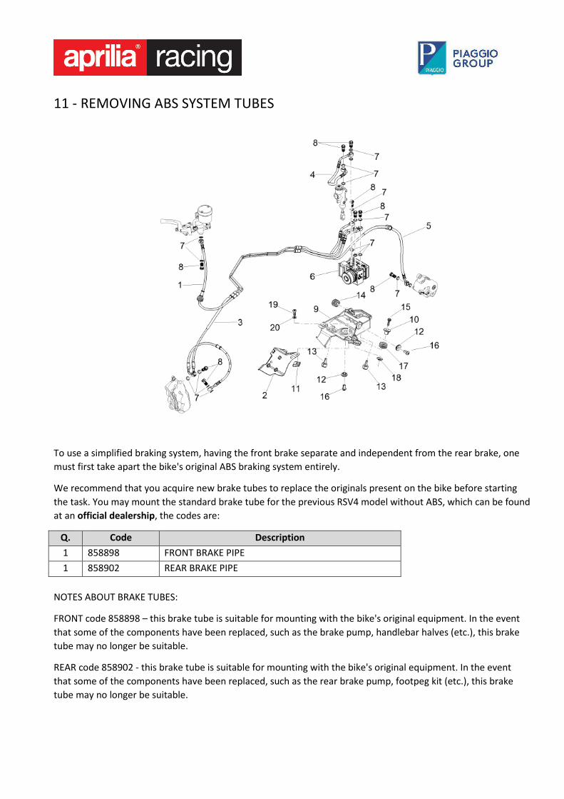
11 - REMOVING ABS SYSTEM TUBES
To use a simplified braking system, having the front brake separate and independent from the rear brake, one
must first take apart the bike's original ABS braking system entirely.
We recommend that you acquire new brake tubes to replace the originals present on the bike before starting
the task. You may mount the standard brake tube for the previous RSV4 model without ABS, which can be found
at an official dealership, the codes are:
Q. Code Description
1 858898 FRONT BRAKE PIPE
1 858902 REAR BRAKE PIPE
NOTES ABOUT BRAKE TUBES:
FRONT code 858898 – this brake tube is suitable for mounting with the bike's original equipment. In the event
that some of the components have been replaced, such as the brake pump, handlebar halves (etc.), this brake
tube may no longer be suitable.
REAR code 858902 - this brake tube is suitable for mounting with the bike's original equipment. In the event
that some of the components have been replaced, such as the rear brake pump, footpeg kit (etc.), this brake
tube may no longer be suitable.

This work needs to be done with the engine removed, because some of the tubing for the brake system runs
through the engine and is fixed bellow the wiring harness cover, inside the frame on the right side.
First of all, the screws that connect the brake tubes to the front brake callipers need to be removed and
containers need to be placed below the tubes to catch the oil as it runs out. The same operation is then done to
remove the tube connected to the rear brake calliper, once again having something to catch the oil is a good
idea. Now, one can remove the bolt that joins the front brake tube to the pump and leave it disconnected long
enough for the oil to flow down into the drainage tubs. Next, loosen the tube on the rear brake pump before
loosening the tubes above the ABS control unit. After having drained the oil from the system, you may proceed
by removing all the brake tubes from the bike. Removing the ABS control unit to drain any oil inside is also
advisable. After having thoroughly cleaned and degreased the control unit, you will need to stop up the holes
located near the bands used to fasten the tubes, these will no longer be used. Having done that, you may mount
the ABS control unit in its original position and reconnect it to the main wiring harness. At this point, you may
proceed with mounting the new brake tubes and purging the systems.
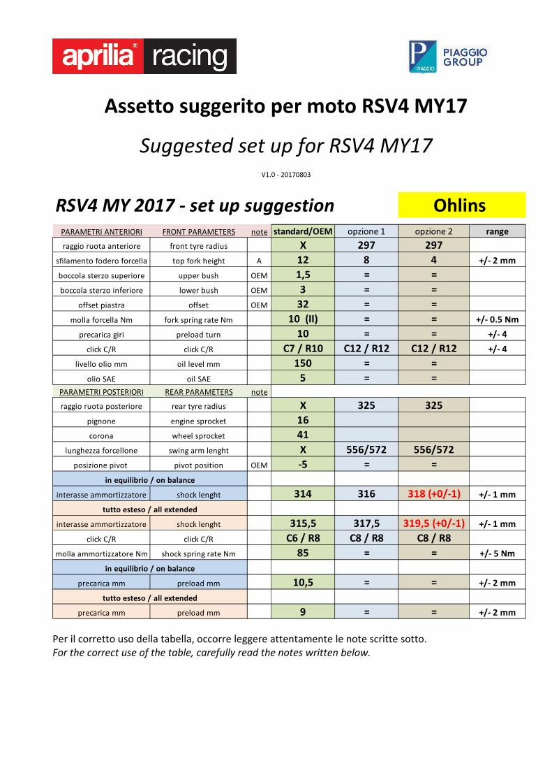
Assetto suggerito per moto RSV4 MY17
Suggested set up for RSV4 MY17
V1.0 - 20170803
RSV4 MY 2017 - set up suggestion Ohlins
PARAMETRI ANTERIORI FRONT PARAMETERS note standard/OEM opzione 1 opzione 2 range
raggio ruota anteriore front tyre radius X 297 297
sfilamento fodero forcella top fork height A 12 8 4 +/- 2 mm
boccola sterzo superiore upper bush OEM 1,5 = =
boccola sterzo inferiore lower bush OEM 3 = =
offset piastra offset OEM 32 = =
molla forcella Nm fork spring rate Nm 10 (II) = = +/- 0.5 Nm
precarica giri preload turn 10 = = +/- 4
click C/R click C/R C7 / R10 C12 / R12 C12 / R12 +/- 4
livello olio mm oil level mm 150 = =
olio SAE oil SAE 5 = =
PARAMETRI POSTERIORI REAR PARAMETERS note
raggio ruota posteriore rear tyre radius X 325 325
pignone engine sprocket 16
corona wheel sprocket 41
lunghezza forcellone swing arm lenght X 556/572 556/572
posizione pivot pivot position OEM -5 = =
interasse ammortizzatore shock lenght 314 316 318 (+0/-1) +/- 1 mm
interasse ammortizzatore shock lenght 315,5 317,5 319,5 (+0/-1) +/- 1 mm
click C/R click C/R C6 / R8 C8 / R8 C8 / R8
molla ammortizzatore Nm shock spring rate Nm 85 = = +/- 5 Nm
precarica mm preload mm 10,5 = = +/- 2 mm
precarica mm preload mm 9 = = +/- 2 mm
in equilibrio / on balance
tutto esteso / all extended
in equilibrio / on balance
tutto esteso / all extended
Per il corretto uso della tabella, occorre leggere attentamente le note scritte sotto.
For the correct use of the table, carefully read the notes written below.
Important things to keep in mind when reading the table of
recommended set-up.
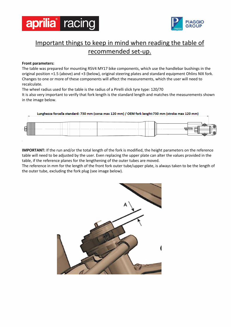
Front parameters:
The table was prepared for mounting RSV4 MY17 bike components, which use the handlebar bushings in the
original position +1.5 (above) and +3 (below), original steering plates and standard equipment Ohlins NIX fork.
Changes to one or more of these components will affect the measurements, which the user will need to
recalculate.
The wheel radius used for the table is the radius of a Pirelli slick tyre type: 120/70
It is also very important to verify that fork length is the standard length and matches the measurements shown
in the image below.
IMPORTANT: If the run and/or the total length of the fork is modified, the height parameters on the reference
table will need to be adjusted by the user. Even replacing the upper plate can alter the values provided in the
table, if the reference planes for the lengthening of the outer tubes are moved.
The reference in mm for the length of the front fork outer tube/upper plate, is always taken to be the length of
the outer tube, excluding the fork plug (see image below).
Rear parameters:
The table was prepared for mounting RSV4 MY17 bike components, which use the -5 engine position, the
swingarm pivot in position -5 and the new red double connecting rod. Changes to one or more of these
components will affect the measurements, which the user will need to recalculate.
The wheel radius used for the table is the radius of a Pirelli slick tyre type: 200/55
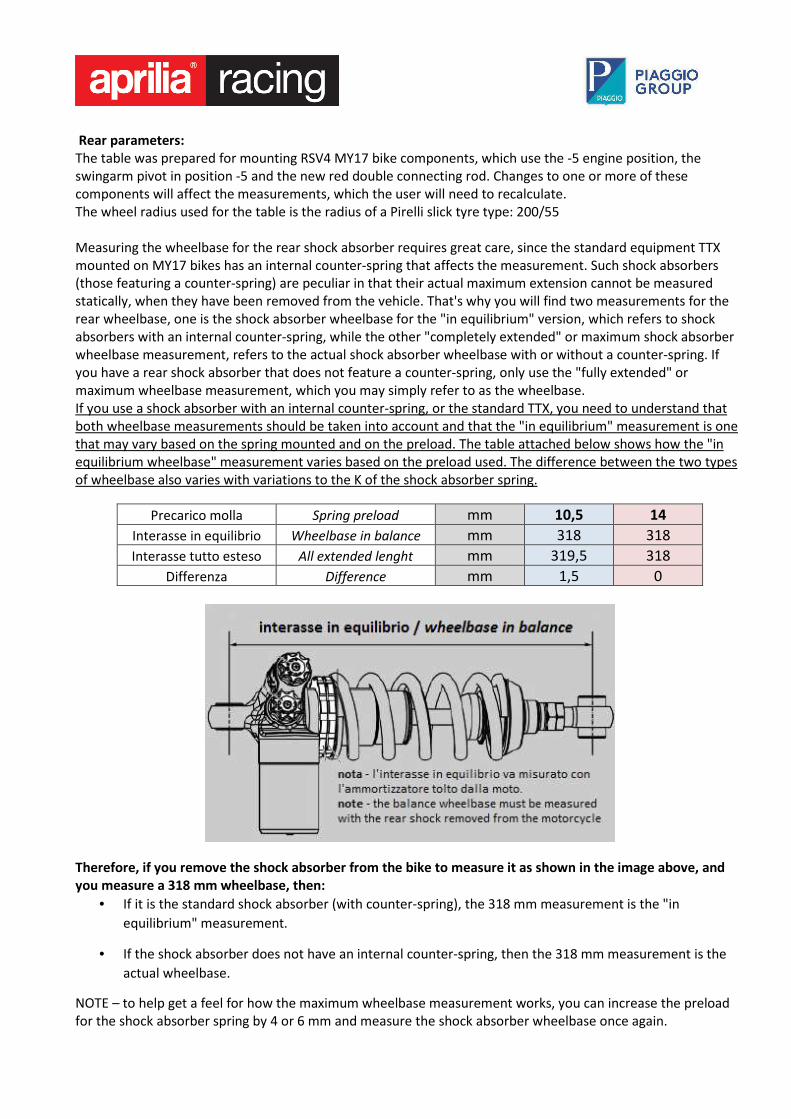
Measuring the wheelbase for the rear shock absorber requires great care, since the standard equipment TTX
mounted on MY17 bikes has an internal counter-spring that affects the measurement. Such shock absorbers
(those featuring a counter-spring) are peculiar in that their actual maximum extension cannot be measured
statically, when they have been removed from the vehicle. That's why you will find two measurements for the
rear wheelbase, one is the shock absorber wheelbase for the "in equilibrium" version, which refers to shock
absorbers with an internal counter-spring, while the other "completely extended" or maximum shock absorber
wheelbase measurement, refers to the actual shock absorber wheelbase with or without a counter-spring. If
you have a rear shock absorber that does not feature a counter-spring, only use the "fully extended" or
maximum wheelbase measurement, which you may simply refer to as the wheelbase.
If you use a shock absorber with an internal counter-spring, or the standard TTX, you need to understand that
both wheelbase measurements should be taken into account and that the "in equilibrium" measurement is one
that may vary based on the spring mounted and on the preload. The table attached below shows how the "in
equilibrium wheelbase" measurement varies based on the preload used. The difference between the two types
of wheelbase also varies with variations to the K of the shock absorber spring.
Precarico molla Spring preload mm 10,5 14
Interasse in equilibrio Wheelbase in balance mm 318 318
Interasse tutto esteso All extended lenght mm 319,5 318
Differenza Difference mm 1,5 0
Therefore, if you remove the shock absorber from the bike to measure it as shown in the image above, and
you measure a 318 mm wheelbase, then:
• If it is the standard shock absorber (with counter-spring), the 318 mm measurement is the "in
equilibrium" measurement.
• If the shock absorber does not have an internal counter-spring, then the 318 mm measurement is the
actual wheelbase.
NOTE – to help get a feel for how the maximum wheelbase measurement works, you can increase the preload
for the shock absorber spring by 4 or 6 mm and measure the shock absorber wheelbase once again.

Each individual user needs to know how the bike will be used, and the system used to measure the shock
absorber wheelbase will need to be adjusted to suit that use. For sporadic use on the racetrack with a set-up
that doesn't stray much from the standard, the "in equilibrium" wheelbase measurement is preferable, as
described in the use and maintenance manual. For exclusive and/or more professional use on the racetrack, one
should always use the maximum wheelbase measurement as a reference.
This is an important and nuanced issue that needs to be properly understood as it will help you discuss the
bike's set-up with a suspensions technician. It is also very important to avoid using wheelbase shock absorber
measurements that go beyond the maximum value mechanically permitted by the link.
The standard TTX for the RSV4 MY17 was designed to limit maximum wheelbase adjustment to 319.5 mm, in
order to avoid exceeding the critical measurement. If this maximum wheelbase measurement is surpassed the
lower uniball for the shock absorber will touch the single connecting rod in the maximum wheelbase position
(see photo below).
12 – MECHANICAL ADJUSTMENT OF ENGINE BRAKE INTERVENTION
The level of mechanical engine braking can be adjusted. To make changes to this parameter, you will need to
work on the spring washer load, which pushes on the clutch drum. The adjustments to be made here depend on
necessity or on the rider's driving style. Each individual user should, therefore, try and determine the best
combination of electrical and mechanical adjustments available. The clutch system for the RSV4 MY17 model is
identical to the previous version (2015/2016), but the set-up for the spring washer is different, which changes
mechanical engine braking. The new model (MY17) has less engine braking than the previous version.
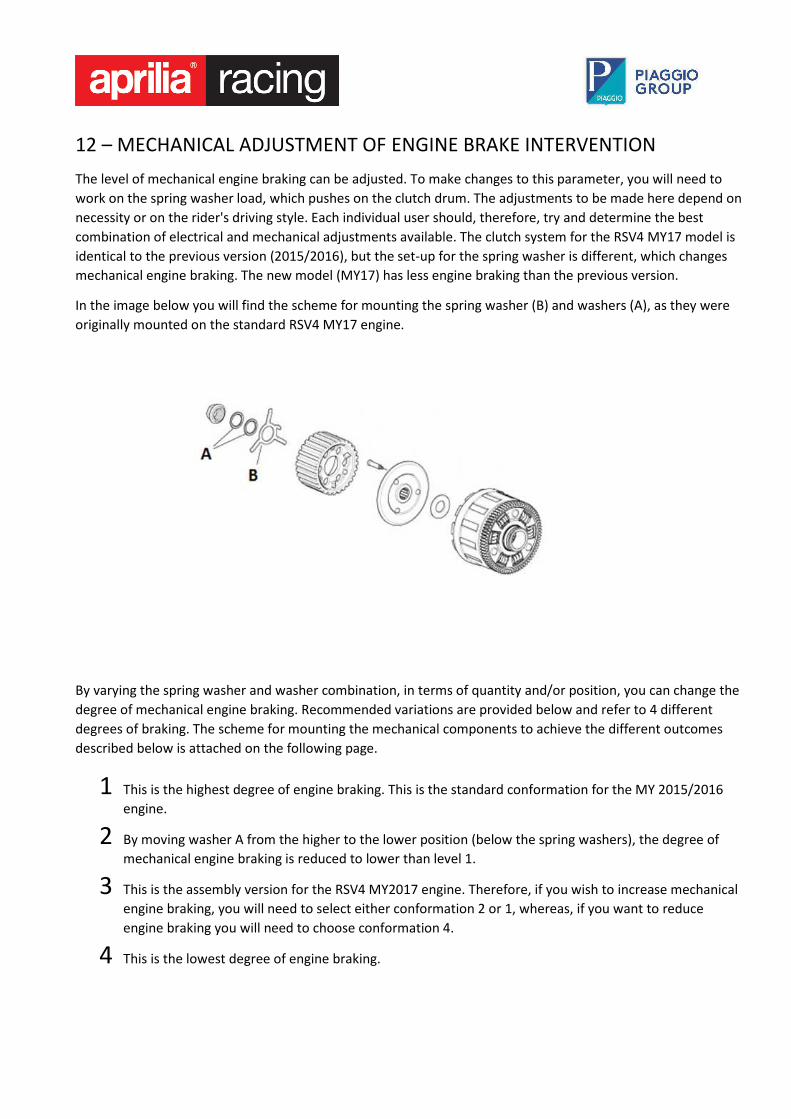
In the image below you will find the scheme for mounting the spring washer (B) and washers (A), as they were
originally mounted on the standard RSV4 MY17 engine.
By varying the spring washer and washer combination, in terms of quantity and/or position, you can change the
degree of mechanical engine braking. Recommended variations are provided below and refer to 4 different
degrees of braking. The scheme for mounting the mechanical components to achieve the different outcomes
described below is attached on the following page.
1 This is the highest degree of engine braking. This is the standard conformation for the MY 2015/2016
engine.
2 By moving washer A from the higher to the lower position (below the spring washers), the degree of
mechanical engine braking is reduced to lower than level 1.
3 This is the assembly version for the RSV4 MY2017 engine. Therefore, if you wish to increase mechanical
engine braking, you will need to select either conformation 2 or 1, whereas, if you want to reduce
engine braking you will need to choose conformation 4.
4 This is the lowest degree of engine braking.
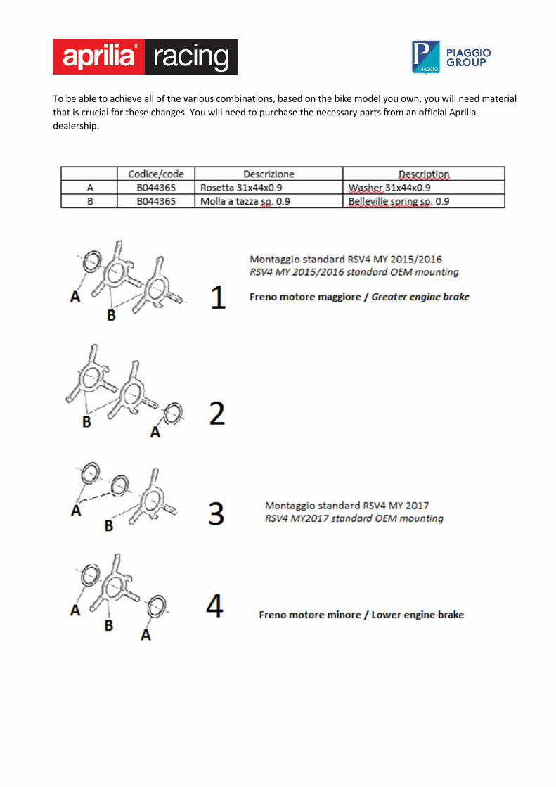
To be able to achieve all of the various combinations, based on the bike model you own, you will need material
that is crucial for these changes. You will need to purchase the necessary parts from an official Aprilia
dealership.