schneider electric services: life-cycle solutions for
TRANSCRIPT

Scopes of Work for Electrical Acceptance Testing
Schneider Electric Services:life-cycle solutions forelectrical distributionequipment
Make the most of your energySM

2 © 2012 -2013 Schneider Electric All Rights Reserved
SECTION 1—INTRODUCTION ........................................................................4SECTION 2—GENERAL REQUIREMENTS .......................................................5SECTION 3—AC DRIVES ..................................................................................6SECTION 4—AIR SWITCHES: LOW VOLTAGE ..............................................8SECTION 5—AIR SWITCHES: MEDIUM VOLTAGE, METAL-ENCLOSED .....10SECTION 6—AIR SWITCHES: HIGH AND
MEDIUM VOLTAGE, OPEN STYLE ..........................................12SECTION 7—SWITCHES: HVL/cc ..................................................................13SECTION 8—METERING DEVICES ................................................................15SECTION 9—BUSWAYS, METAL- ENCLOSED ..............................................16SECTION 10—OUTDOOR / SUBSTATION BUS ...........................................17SECTION 11—CABLES: LOW VOLTAGE ......................................................18SECTION 12—CABLES: MEDIUM VOLTAGE ................................................19SECTION 13—CAPACITORS: POWER FACTOR
CORRECTION...........................................................................20SECTION 14—CIRCUIT BREAKERS: LOW VOLTAGE INSULATED
CASE/ MOLDED CASE ...........................................................21SECTION 15—CIRCUIT BREAKERS: LOW VOLTAGE
POWER (ANSI/IEEE C37.13) ..................................................23SECTION 16—CIRCUIT BREAKERS: MEDIUM VOLTAGE SF6 ....................25SECTION 17—CIRCUIT BREAKERS:
MEDIUM VOLTAGE VACUUM ................................................27SECTION 18—DIRECT CURRENT SYSTEMS:
BATTERIES AND CHARGERS ..............................................29SECTION 19—EMERGENCY SYSTEMS:
AUTOMATIC TRANSFER SWITCHES ...................................30SECTION 20—GROUND-FAULT PROTECTION SYSTEMS ...........................32SECTION 21—GROUND RESISTORS ............................................................34SECTION 22—GROUNDING SYSTEMS .........................................................35SECTION 23—ISOLATED POWER SYSTEMS ...............................................36SECTION 24—MOTOR CONTROL CENTERS:
LOW AND MEDIUM VOLTAGE ...............................................38SECTION 25—MOTOR STARTERS: LOW VOLTAGE ....................................41SECTION 26—MOTOR STARTERS: MEDIUM VOLTAGE ..............................42SECTION 27—PROTECTIVE RELAYS ............................................................44SECTION 28—STEP VOLTAGE REGULATORS .............................................45SECTION 29—SURGE ARRESTERS: LOW VOLTAGE SURGE
PROTECTION DEVICES .........................................................47SECTION 30—SURGE ARRESTERS: MEDIUM AND HIGH
VOLTAGE SURGE PROTECTION DEVICES ..........................48SECTION 31—SWITCHGEAR AND SWITCHBOARD
ASSEMBLIES: LOW AND MEDIUM VOLTAGE ......................49SECTION 32—SWITCHGEAR DVCAS-38 .......................................................52SECTION 33—TRANSFORMERS: DRY TYPE: ALL
VOLTAGES - LARGE (GREATER THAN 167SINGLE-PHASE AND 500KVA THREE-PHASE)......................53
TABLE OF CONTENTS
Scopes of Work for Electrical Acceptance Testing:TABLE OF CONTENTS
Bulletin No. 1910DB1302 March 2013

Bulletin No. 1910DB1302 March 2013
3© 2012 -2013 Schneider Electric All Rights Reserved
TABLE OF CONTENTS SECTION 34—TRANSFORMERS: DRY TYPE - SMALL (167KVA SINGLE-PHASE, 500KVA THREE-PHASE, AND SMALLER) ..........................54
SECTION 35—TRANSFORMERS, INSTRUMENT .......................................55SECTION 36—TRANSFORMERS: LIQUID-FILLED:
ALL VOLTAGES ...................................................................57
LIST OF TABLES
Scopes of Work for Electrical Acceptance Testing: TABLE OF CONTENTS
TABLE: 100.1. Insulation Resistance Test Values Electrical Apparatus and Systems .......................................59
TABLE: 100.2 Switchgear Withstand Test Voltages ......................................60TABLE: 100.3 Recommended Dissipation Factor/Power Factor at
20° C Liquid-Filled Transformers, Regulators, and Reactors Acceptance Test Values .......................................................61
TABLE: 100.4 Insulating Fluid Limits .............................................................62TABLE: 100.5 Transformer Insulation Resistance
Acceptance Testing ................................................................64TABLE: 100.6 Medium-Voltage Cables Acceptance Test Values .................65TABLE: 100.7 Inverse Time Trip Test at 300% of
Rated Continuous Current of Circuit Breaker Molded-Case Circuit Breakers .................................................68
TABLE: 100.8 Instantaneous Trip Tolerances for Field Testing of Circuit Breakers ........................................69
TABLE: 100.9 Instrument Transformer Dielectric TestsField Acceptance .....................................................................70
TABLE: 100.10 Maximum Allowable Vibration Amplitude ..............................71TABLE: 100.11 — RESERVED — ..............................................................72TABLE: 100.12 Bolt-Torque Values for Electrical Connections .....................73TABLE: 100.13 SF6 Gas Tests .....................................................................76TABLE: 100.14 Insulation Resistance Conversion Factors (20° C) ...............77TABLE: 100.15 High-Potential Test Voltage
Automatic Circuit Reclosers ...................................................79TABLE: 100.16 High-Potential Test Voltage for Acceptance
Testing of Line Sectionalizers ................................................80TABLE: 100.17 Dielectric Withstand Test Voltages
Metal-Enclosed Bus ...............................................................81TABLE: 100.18 Thermographic Survey
Suggested Actions Based on Temperature Rise ...................82TABLE: 100.19 Dielectric Withstand Test Voltages
Electrical Apparatus Other than Inductive Equipment ...........83TABLE: 100.20 Rated Control Voltages and
their Ranges for Circuit Breakers ..........................................84TABLE: 100.21 Accuracy of IEC Class TP Current Transformers
Error Limit ..............................................................................86TABLE: 100.22 Minimum Radii for Power Cable
Single & Multiple Conductor Cables with Interlocked Armor, Smooth or Corrugated Aluminum Sheath or Lead Sheath ....87
TABLE: 100.23 Recommended Torque Values for Field Installed Wiring, Bus and Cable Connetions ................88
TABLE: 100.24 Maximum Micro-Ohms Per Pole ...........................................90TABLE: 100.25 Maximum Micro-Ohms Per Pole............................................91TABLE: 100.26 Maximum Micro-Ohms Per Pole ............................................91TABLE: 100.27 Type DS, DSII, DSL, and DSLII Circuit Breaker ....................92
SECTION XX—FUTURESECTION XX—FUTURE
4 © 2012 -2013 Schneider Electric All Rights Reserved
SECTION 1—INTRODUCTION This bulletin details the inspection and testing procedures that Schneider Electric Services technicians follow while performing acceptance testing of electrical equipment. These inspections and tests are performed on new equipment, after installation and prior to energizing, in order to:
1. Check that the equipment has not been damaged during shipment orinstallation;
2. Verify that the equipment is in compliance with the purchase specificationand design intent; and
3. Document test results that can serve as benchmarks for future tests.
The standard deliverables to the customer are those services described in the each section of these procedures and titled Visual and Mechanical Inspection and Electrical Tests. Optional Tests will only be performed by Schneider Electric technicians when specified on the customer’s purchase order and subsequent field service work order.
For testing of equipment not detailed in this document, Schneider Electric Services will refer to manufacturers instructions, NFPA 70B, IEEE, ANSI and other relevant standards.
For additional information, contact Schneider Electric Services at 1-888-778-2733.
This document has been prepared based on manufacturer instruction bulletins, NFPA, IEEE, NEMA and ANSI standards
Tables are based on information from Schneider Electric USA, Inc. and the ANSI/NETA Standard for Acceptance Testing Specifications for Electrical Power Equipment and Systems
Acknowledgement
Scopes of Work for Electrical Acceptance Testing: SECTION 1—INTRODUCTION
Bulletin No. 1910DB1302 March 2013

Bulletin No. 1910DB1302 March 2013
5© 2012 -2013 Schneider Electric All Rights Reserved
SECTION 2—GENERALREQUIREMENTS
• Schneider Electric Services (SES) considers the safety of our employees,customers and all persons associated or affected by our work to be ourhighest priority. All work performed by Schneider Electric will adhereto Schneider Electric Safe Work practices, NFPA 70E, CustomerRequirements and State and Federal standards. In all cases the moststringent procedures will be adhered to. At any point if the lead SchneiderElectric representative determines work cannot proceed safely inaccordance with these requirements work will be halted until a mutuallyagreeable resolution is reached.
• Owner / Customer shall supply current one-line and as built drawings forreview prior to commencement of work. These will be given to SchneiderElectric Personnel for use throughout the testing project.
• Owner / Customer shall supply OEM (Original Equipment Manufacture)Operations and Maintenance Manuals for all equipment to be tested.Copies of these should be given to Schneider Electric Personnel for usethroughout the testing project.
• Schneider Electric Services Employees are NOT AUTHORIZED towork on energized equipment. However, there are occasions in whichit may be necessary to take voltage measurements within an energizedenclosure. These measurements will be taken using all applicableprocedures for energized work.
• Schneider Electric Services does not typically perform shutdown and/orswitching operations, because these operations may result in damage toproperty or persons downstream of the equipment as a result of conduct,errors, or omissions made by others. If a customer requests SchneiderElectric Company to perform such services, a copy of the SchneiderElectric Shutdown/Switching policy must be reviewed and signed by thecustomer. The onsite technician(s) must also contact their Manager forapproval and proper procedures prior to performing any shutdown and/orswitching.
• Schneider Electric maintains an equipment calibration program to assurethat the equipment used to monitor and measure data associated withkey characteristics will provide data that is both accurate and repeatable.The calibration cycle is defined by manufacturer and industry guidelines.Equipment included in the program is identified by a calibration stickeror tag affixed to each piece of test equipment. Equipment calibrationrecords are available for review based on project specifications.
Scopes of Work for Electrical Acceptance Testing: SECTION 2—GENERAL REQUIREMENTS
DANGERHAZARD OF ELECTRIC SHOCK, EXPLOSION, OR ARC FLASH
• Applyappropriatepersonalprotectiveequipment(PPE)andfollowsafeelectricalworkpractices.SeeNFPA70EorCSAZ462.
• Thisequipmentmustbeinstalledandservicedbyqualifiedelectricalpersonnel.
• Turnoffallpowersupplyingthisequipmentbeforeworkingonorinsideequipment.
• Alwaysuseaproperlyratedvoltagesensingdevicetoconfirmpowerisoff.
• Replacealldevices,doorsandcoversbeforeturningonpowertothisequipment.
Failure to follow these instructions will result in death or serious injury.
!

6 © 2012 -2013 Schneider Electric All Rights Reserved
SECTION 3—AC DRIVES A. Visual and Mechanical Inspection1. Document equipment nameplate data on the test report. Verify equipment
nameplate ratings are in accordance with record drawings.2. Check for shipping damage: broken operators, switches, or pilot lights;
dented or bent enclosure structures.3. Check for excessive dirt, dust, or moisture.4. Verify that a properly sized grounding conductor is connected to the drive
grounding lug and terminates on a ground lug in the power distributionpanel.
5. Verify that wires connected between the drive and the motor are correctlysized per the manufacturer’s instructions (if not specified refer to theNational Electrical Code). Verify that these wires are separated from allother wiring (ideally in their own conduit). Note the length of wire betweenthe drive and the motor on the test report.
6. Tighten all power wiring connections to proper torque value. Checkline and load side connections of all disconnect switches, breakers,contactors, and overloads.
7. Check and tighten all control wiring connections, mounting hardware,drive control terminals and terminal block connections.
8. Check door and disconnect switch alignment and opening/closingoperation.
9. Test all mechanical interlocking devices.10. Manually operate all contactors to verify freedom of movement.11. Verify that customer supplied fusing agrees with the manufacturer’s
recommendations.12. Verify mechanical operation of isolation contactor. Tighten power and
control connections. Verify the proper coil voltage rating.13. Verify that all control and option boards are securely fastened and plug-in
terminals are connected.14. Check that properly sized thermal overloads are used in ISO/Bypass unit.15. Set / program the drive based on the customer provided settings.
Settings should include torque type and any applicable communicationsparameters. If customer provided settings are not available, consult withthe customer regarding any recommended settings.
16. Document final settings and customer acceptance of final settings.
B. Electrical Tests
1. Verify that the incoming line voltage at the line side of the disconnectingmeans is within ± 10% of the input voltage rating on the drive nameplate.
2. Set the AFC-Off-Bypass selector switch (if used) to AFC and the Hand Off-Auto to Hand. Slowly turn the manual speed potentiometer clockwiseto accelerate the motor. Check the direction of motor rotation at 10hz.Rotation should be clockwise (ABC) unless indicated differently by theproject documentation. Note the as-found and as-left rotation on the start-up documentation.
3. Set the AFC-Off-Bypass selector switch (if used) to Bypass and theHand Off-Auto to Hand. Check the direction of motor rotation. Rotationshould be clockwise (ABC) unless indicated differently by the projectdocumentation. Note the as-found and as-left rotation on the start-updocumentation.
Scopes of Work for Electrical Acceptance Testing: SECTION 3—AC DRIVES
Bulletin No. 1910DB1302 March 2013

Bulletin No. 1910DB1302 March 2013
7© 2012 -2013 Schneider Electric All Rights Reserved
4. Measure the output voltage of the ac control transformers. Voltagesshould be within +/-5% of nominal output voltage. Measure dccontrol supplies (for customer use), and verify that they are within themanufacturer’s recommendations.
5. Measure the dc bus voltage and verify that it is equal to the measuredRMS Line to Line input voltage x 1.414 +/-5%.
6. With the motor load disconnected, perform phase to phase and phaseto ground voltage measurements at the output terminals (T leads). Takemeasurements in each of the following modes; standby, medium motorload and full motor load. Phase to Phase voltage imbalance must beless than +/-2%. Phase to ground voltage imbalance should be less than+/-5%.
7. Repeat the previous step with the motor load connected.8. Measure the motor current in each “T lead” at medium motor load and
again at full motor load. Output Phase Current imbalance must be lessthan 5% at any load. Compare readings taken to displayed value ofoutput current on the Keypad. Note any discrepancies on the test report.
9. Verify that speed control signals vary within the voltage or current rangeof the input to which they are connected. Check for proper shielding onwires connected to speed control inputs. Verify that signals are isolatedfrom power wires.
10. Verify proper operation based on the High Speed (HSP) setting(maximum motor speed setting). Record your results.
11. Verify proper operation based on Check the Low Speed (LSP) setting(minimum motor speed setting). Record your results.
12. Verify proper operation of acceleration (ACC) and deceleration (DEC)times.
13. Verify that I/O points are assigned to proper functions per factorydrawings.
14. Verify that Hand and Auto controls, Start, Stop, and speed input, operatethe drive correctly.
15. Check that all indicating lamps illuminate only for their assignedfunctions. Check all Push to Test lamps.
Scopes of Work for Electrical Acceptance Testing: SECTION 3—AC DRIVES

Bulletin No. 1910DB1302 March 2013
8 © 2012 -2013 Schneider Electric All Rights Reserved
SECTION 4—AIR SWITCHES: LOW VOLTAGE
A. Visual and Mechanical Inspection
1. Document equipment nameplate data on test report. Verify equipmentnameplate ratings are in accordance with the record drawings.
2. Inspect physical and mechanical condition.3. Confirm application of lubricants at manufacturer’s recommended
locations.4. Verify appropriate anchorage and required area clearances.5. Verify appropriate equipment grounding.6. Verify correct blade alignment, blade penetration, travel stops, and
mechanical operation.7. Verify and record fuse sizes and types are in accordance with record
drawings and, if available, coordination studies.8. Using a calibrated torque wrench or low resistance ohmmeter, verify
that the tightness of accessible bolted connections and/or cableconnections are in accordance with the manufacturer’s published data. Ifno manufacturer’s data is available, use the values in Table 100.12 and100.23.
9. Check all interlocking systems for correct operation and sequencing, andkey distribution, if applicable.
10. Verify correct phase barrier installation.11. Inspect all indicating and control devices for correct operation.12. Check the condition of arc contacts and arc chutes.
B. Electrical Tests
NOTE: When performing dielectric tests, you must disconnect all Instrument and Control Transformers, Arresters, TVSS units, and other sensitive electronic equipment that may cause erroneous results or be damaged by the applied test voltage. Verify no paths to ground exist with an ohmmeter or initially testing insulation resistance at a low voltage.
Record the date of the last calibration for each piece of test equipment used.
1. Perform insulation-resistance tests on each pole, phase-to-phase andphase-to-ground with switch closed and across each open pole forone minute. Test voltage shall be in accordance with manufacturer’spublished data or Table 100.1.
2. Test all auxiliary devices (solenoid trip, blown main fuse detector, etc.) forproper operation.
3. Perform a Contact Resistance Test across each pole (phase):a. With the main power source de-energized, close and open the switch
several times using either manual or electrical means.b. Apply a minimum current of 10 amperes dc through the closed
contacts. If the test current does not conform to the manufacturer’sspecification, consult the manufacturer.
Scopes of Work for Electrical Acceptance Testing: SECTION 4—AIR SWITCHES: LOW VOLTAGE

Bulletin No. 1910DB1302 March 2013
9© 2012 -2013 Schneider Electric All Rights Reserved
c. Measure and record the median (middle) value of three readings(toggling the circuit breaker between each reading) compare with themanufacturers published information and adjacent poles.
d. If the measured resistances are below the manufacturers publisheddata and balanced, the condition of the device contacts is consideredsuitable for service. If the measured resistances exceed themanufacturers recommendations or are imbalanced, open andclose the device several more times and repeat the test. Contact thefactory if acceptable values of resistance cannot be achieved.
4. Measure fuse resistance to verify continuity, record your results.5. When ground fault protection is installed on switch, confirm settings are
in accordance with the owner supplied coordination study. Verify propercalibration and operation by current injection.
Scopes of Work for Electrical Acceptance Testing: SECTION 4—AIR SWITCHES: LOW VOLTAGE

10 © 2012 -2013 Schneider Electric All Rights Reserved
SECTION 5—AIR SWITCHES: MEDIUM VOLTAGE, METAL-ENCLOSED
A. Visual and Mechanical Inspection
1. Document equipment nameplate data on test report. Verify equipmentnameplate ratings are in accordance with the record drawings.
2. Inspect physical and mechanical condition.3. Confirm correct application of lubricants at manufacturer’s recommended
locations.4. Verify appropriate anchorage and required area clearances.5. Verify appropriate equipment grounding.6. Verify correct blade alignment, blade penetration, travel stops, and
mechanical operation.7. Verify that fuse sizes and types are in accordance with drawings and, if
available, coordination studies.8. Inspect fuse holders for tightness and alignment.9. Verify that expulsion-limiting devices are in place on all holders having
expulsion-type elements. Verify that they are installed to vent in theproper direction.
10. Using a calibrated torque wrench or low resistance ohmmeter, verify thatthe tightness of accessible bolted connections and/or cable connectionsare in accordance with the manufacturer’s published data. If nomanufacturer’s data is available, use the values in Tables 100.12 and100.23.
11. Check all interlocking systems for correct operation and sequencing, andkey distribution, if applicable.
12. Verify correct phase-barrier installation.13. Inspect all indicating and control devices for correct operation.14. Verify that the Lightning arresters have been connected. Verify that they
have the proper voltage rating per the manufacturer’s drawings.
B. Electrical Tests
NOTE: When performing dielectric tests, disconnect all Instrument and Control Transformers, Arresters, TVSS units, and other sensitive electronic equipment that may cause erroneous results or cause damage to equipment that is not rated in accordance with Switchgear industry standards. Verify no paths to ground exist with an ohmmeter or initially testing insulation resistance at a low voltage
Record the date of the last calibration for each piece of test equipment used.
1. Perform insulation-resistance tests on each pole, phase-to-phase andphase-to-ground with switch closed and across each open pole for oneminute. Test voltage shall be in accordance with manufacturer’s publisheddata or Table 100.1.
2. Perform a dielectric test (Hi-Pot) on each pole with switch closed. Testeach pole-to-ground with all other poles grounded. Test voltage shall bein accordance with manufacturer’s published data or Table 100.2.
3. Verify that heaters have been connected and are operating properly.
Scopes of Work for Electrical Acceptance Testing: SECTION 5—AIR SWITCHES: MEDIUM VOLTAGE, METAL-ENCLOSED
Bulletin No. 1910DB1302 March 2013

Bulletin No. 1910DB1302 March 2013
11© 2012 -2013 Schneider Electric All Rights Reserved
4. Measure fuse resistance to verify continuity, record your results.5. Perform a Contact Resistance Test across each pole (phase)
a. With the main power source de-energized, close and open the switchseveral times using either manual or electrical means.
b. Apply a minimum current of 10 amperes dc through the closedcontacts.
c. Measure and record the median (middle) value of three readings(toggling the circuit breaker between each reading) compare with themanufacturers published information and adjacent poles.
d. If the measured resistances are below the manufacturers publisheddata and balanced, the condition of the device contacts isconsidered suitable for service. If the measured resistances exceedthe manufacturers recommendations or are imbalanced, open andclose the device several more times and repeat the test. Contact thefactory if acceptable values of resistance cannot be achieved.
Scopes of Work for Electrical Acceptance Testing: SECTION 5—AIR SWITCHES: MEDIUM VOLTAGE, METAL-ENCLOSED

12 © 2012 -2013 Schneider Electric All Rights Reserved
SECTION 6—AIR SWITCHES: HIGH AND MEDIUM VOLTAGE, OPEN STYLE
A. Visual and Mechanical Inspection
1. Document equipment nameplate data on test report. Verify equipmentnameplate ratings are in accordance with the record drawings.
2. Inspect physical and mechanical condition.3. Confirm correct application of lubricants at manufacturer’s recommended
locations.4. Verify that grounding is in accordance with industry standards and project
specifications.5. Using a calibrated torque wrench or low resistance ohmmeter, verify that
the tightness of accessible bolted connections and/or cable connectionsare in accordance with the manufacturer’s published data. If no,manufacturer’s data is available, use the values in Tables 100.12 and100.23.
6. Perform mechanical operator tests in accordance with manufacturer’sinstructions.
7. Verify correct operation and adjustment of motor operator limit-switchesand mechanical interlocks.
8. Verify correct blade alignment, blade penetration, travel stops, arcinterrupter operation, and mechanical operation (over toggle).
9. Inspect fuse holders for tightness and alignment.10. Check the condition of arc contacts and arc chutes.
B. Electrical Tests
NOTE: When performing dielectric tests, disconnect all Instrument and Control Transformers, Arresters, TVSS units, and other sensitive electronic equipment that may cause erroneous results or cause damage to equipment that is not rated in accordance with Switchgear industry standards. Verify no paths to ground exist with an ohmmeter or initially testing insulation resistance at a low voltage
Record the date of the last calibration for each piece of test equipment used.
1. Perform insulation-resistance tests on each pole, phase-to-phase andphase-to-ground with switch closed and across each open pole forone minute. Test voltage should be in accordance with manufacturer’spublished data or Table 100.1.
2. Perform a dielectric test (Hi-Pot) on each pole with switch closed. Testeach pole-to-ground with all other poles grounded. Test voltage shall bein accordance with manufacturer’s published data or Table 100.2.
3. Perform a contact-resistance test across each switch blade and fuseholder, record results. Compare with the manufacturer’s publishedinformation and adjacent poles. Investigate any values that deviate fromadjacent poles or similar switches by more than 25 percent.
4. Verify Operator targets and Gas targets, where applicable, are in propersequence.
Scopes of Work for Electrical Acceptance Testing: SECTION 6—AIR SWITCHES: HIGH AND MEDIUM VOLTAGE, OPEN STYLE
Bulletin No. 1910DB1302 March 2013

Bulletin No. 1910DB1302 March 2013
13© 2012 -2013 Schneider Electric All Rights Reserved
SECTION 7—SWITCHES: HVL/cc A. Visual and Mechanical Inspection
1. Document equipment nameplate data on test report. Verify equipmentnameplate ratings are in accordance with the record drawings.
2. Inspect physical and mechanical condition.3. Verify appropriate anchorage and required area clearances4. Verify that all power cables are properly terminated and supported.
NOTE: When routing shielded cable through window-type currenttransformers or ground sensor current transformers, the shield-groundconnection wire is normally routed back through the current transformerand solidly grounded
5. Check all control wiring for compliance with the wiring diagrams andconnection across shipping splits.
6. If FuseLogic™ fuse trip system is installed, verify proper operation.7. Verify that all connections are properly made and tightened to the proper
torque values,8. Using a calibrated torque wrench or low resistance ohmmeter, verify that
the tightness of accessible bolted connections and/or cable connectionsare in accordance with the manufacturer’s published data. If nomanufacturer's data is available, use the values in Tables 100.12 and100.23.
9. Verify all fuses are properly installed and clips lubricated with Mobil 28.10. Verify that fuse sizes and types are in accordance with drawings and, if
available, coordination studies.11. Verify all current transformer circuits are complete and not shorted.12. Check all interlocking systems for correct operation and sequencing, and
key distribution, if applicable.13. If any isolating switch is not in operation and is left without incoming
cables, the corresponding grounding switch must be closed and blockedby means of a padlock to avoid possible unintentional operation.
14. Verify appropriate equipment grounding.15. Verify that all insulating surfaces are clean and dry.16. Verify that all barriers and covers are secured17. When equipped, verify proper operation of the ground switch and related
interlocks.18. Perform a minimum of 5 open / close operations while verifying smooth
operation of the mechanism and all indicators.19. Inspect all interlocks, indicating and control devices for correct operation.
Scopes of Work for Electrical Acceptance Testing: SECTION 7—SWITCHES: HVL/cc

14 © 2012 -2013 Schneider Electric All Rights Reserved
B. Electrical Tests
NOTE: Prior to performing dielectric tests, disconnect all Instrument and Control Transformers, Arresters, Control and Power cables units, and other sensitive electronic equipment that may cause erroneous results or be damaged by the applied test voltage. Capacitive dividers supplied with the equipment must be properly connected or grounded. Verify no paths to ground exist with an ohmmeter or initially testing insulation resistance at a low voltage.
Record the date of the last calibration for each piece of test equipment used.
1. Perform insulation-resistance tests on each pole, phase-to-phase andphase-to-ground with switch closed and across each open pole for oneminute. Test voltage shall be in accordance with the below table.
2. Perform Hi-Pot testa. Apply voltage to each phase individually for one minute with the
other two phases and enclosure grounded. (see below table for hi-pot test values
b. Gradually increase voltage.
Hi-Pot Test ValuesEquipment
RatingField Test Voltages
AC DC
4.76kV 14kV 20kV
15kV 27kV 38kV
17.5kV 28.5kV 40kV
27kV 45kV 63kV
38kV 60kV 85kV
Scopes of Work for Electrical Acceptance Testing: SECTION 7—SWITCHES: HVL/cc
Bulletin No. 1910DB1302 March 2013

Bulletin No. 1910DB1302 March 2013
15© 2012 -2013 Schneider Electric All Rights Reserved
SECTION 8—METERING DEVICES A. Visual and Mechanical Inspection1. Document equipment nameplate data on test report. Verify equipment
nameplate ratings are in accordance with the record drawings.2. Inspect physical and mechanical condition.3. Confirm case is properly grounded.4. Verify tightness of electrical connections.5. For electro-mechanical devices, verify freedom of movement, correct
travel, alignment, and tightness of mounting hardware.6. For microprocessor based meters confirm and record settings for system
configuration, CT and PT ratios, multipliers, communications and otherspecified parameters are in accordance with record drawings or customersupplied specifications.
B. Electrical Tests
Record the date of the last calibration for each piece of test equipment used.
1. Check calibration of meters according to the manufacturer’s publisheddata.
2. Electrically confirm that current transformer and voltage transformersecondary circuits are intact.
Scopes of Work for Electrical Acceptance Testing: SECTION 8—METERING DEVICES

16 © 2012 -2013 Schneider Electric All Rights Reserved
SECTION 9—BUSWAYS, METAL- ENCLOSED 1. Document equipment nameplate data on test report. Verify busway
nameplate ratings in accordance with record drawings.2. Inspect the busway for physical damage and correct connection in
accordance with the record drawings.3. Inspect for appropriate bracing, suspension, alignment, clearances and
enclosure grounding and bonding.4. Verify that the neutral is only grounded at one point in accordance with
NEC, CSA or other applicable standards.5. Using a calibrated torque wrench or low resistance ohmmeter, verify that
the tightness of accessible bolted connections and/or cable connections are in accordance with the manufacturer’s published data. If no manufacturer’s data is available, use the values in Tables 100.12 and 100.23.
6. Verify installation and proper operation of heaters, when applicable,7. Verify that the busway phasing matches the system phasing at all
connection points (transformers, switchboards, tie sections etc.).8. For outdoor busway, confirm removal of “weep-hole” plugs, if applicable,
and the correct installation of joint shield(s). Verify that proper gasketingis in place.
A. Visual and Mechanical Inspection
B. Electrical TestsNOTE: Prior to testing, confirm that all tap-off or plug-in devices are in the off position. Isolate the entire busway run by disconnecting any ties to transformers, switchboards, meters or other devices.
Record the date of the last calibration for each piece of test equipment used.
1. Measure insulation resistance of each busway with an insulationresistance tester rated at 1000 volts. Make measurements phase-to-ground, phase-to-neutral and phase-to-phase and for one minute.Compare your results with Table 100.1.
NOTE: The megohm readings should not be less than the value calculated from the following formula. Megohms = 100 / length of run (in feet) or Megohms = 30.5 / length of run (in meters)
C. Optional Tests
1. Perform contact-resistance test on each connection point of non insulatedbusway. On insulated busway, measure resistance of assembled buswaysections and compare values with adjacent phases.
2. Perform a dielectric test (Hi-Pot) on each busway, phase-to-ground withphases not under test grounded, in accordance with manufacturer’spublished data. Apply test voltage for one minute. Use test voltage valuesas shown in Table 100.17.
Acceptance Testing Procedures:SECTION 9—BUSWAYS, METAL-ENCLOSED
Bulletin No. 1910DB1302 March 2013

Bulletin No. 1910DB1302 March 2013
17© 2012 -2013 Schneider Electric All Rights Reserved
SECTION 10 — OUTDOOR / SUBSTATION BUS A. Visual and Mechanical Inspection1. Document equipment nameplate data on test report. Verify bus
nameplate ratings in accordance with record drawings.2. Inspect the bus for physical damage and correct connection in
accordance with the record drawings.3. Inspect for appropriate bracing, suspension, alignment, and proper
grounding.4. Using a calibrated torque wrench or low resistance ohmmeter, verify that
the tightness of accessible bolted connections and/or cable connections are in accordance with the manufacturer’s published data. If no, manufacturer’s data is available, use the values in Tables 100.12 and 100.23.
5. Verify that all support insulators are clean and undamaged.6. Verify that the bus phasing matches the system phasing at all connection
points (transformers, circuit breakers, switches, tie sections etc.).
B. Electrical Tests
Record the date of the last calibration for each piece of test equipment used.
1. Perform an insulation resistance test to confirm the system is free of anyground faults. Compare your results with Table 100.1.
2. Perform a dielectric test (Hi-Pot) on each bus, phase-to-ground withphases not under test grounded, in accordance with manufacturer’spublished data. Apply test voltage for one minute. Use test voltage valuesas shown in Table 100.17.
1. Perform contact-resistance test on each connection point.
C. Optional Tests
Acceptance Testing Procedures:SECTION 10— OUTDOOR / SUBSTATION BUS
18 © 2012 -2013 Schneider Electric All Rights Reserved
SECTION 11—CABLES: LOW VOLTAGE1. Verify that cable sizing and insulation temperature rating are in
accordance with final approved or record drawings and specifications, ifavailable. Note any deviations.
2. Inspect the exposed sections of cables for physical damage and correctconnection in accordance with the record drawings.
3. Using a calibrated torque wrench, verify that the tightness of accessiblebolted connections is in accordance with the manufacturer’s publisheddata. If no manufacturer’s data is available, use the values in Tables100.12 and 100.23.
4. Inspect compression-applied connectors for correct cable match andindentation.
5. Verify cable color coding with project specifications, where applicable.
A. Visual and Mechanical Inspection
B. Electrical Tests
NOTE: When performing dielectric tests, disconnect all Instrument and Control Transformers, Arresters, TVSS units, and other sensitive electronic equipment that may cause erroneous results or cause damage to equipment that is not rated in accordance with industry standards.
1. Verify that the opposite end of the cable run being tested is properlyisolated from both adjacent equipment and personnel during testing.
2. Record the date of the last calibration date for each piece of testequipment used.
3. Cables and leads shall be tested for continuity to ensure correct cableconnection and phasing.
4. Perform an insulation resistance test on each conductor betweenone conductor and ground with the other conductors grounded. Eachconductor shall be tested in the same manner.a. The test shall be performed at 1000 volts dc for one minute.b. Each 480V feeder cable shall be tested with the cable connected
to the racked-in but open breaker or switch at the equipment.Connection at the other end of each of these cables shall be asfollows:i. Cables to Motor Control Centers shall be connected to the bus
with the switches or breakers in the starters open.ii. Cables to motors and other equipment shall be connected to the
motors and equipment with feeder switches open.
C. Optional Test
Perform a dielectric test on shielded cable or as specified per Table 100.2. Refer to the manufacturer’s published data, Perform at standard intervals, checking leakage current and decay voltage over the specified time period.
Scopes of Work for Electrical Acceptance Testing: SECTION 11—CABLES: LOW VOLTAGE Bulletin No. 1910DB1302
March 2013

Bulletin No. 1910DB1302 March 2013
19© 2012 -2013 Schneider Electric All Rights Reserved
SECTION 12—CABLES: MEDIUM VOLTAGE
A. Visual and Mechanical Inspection
1. Verify that cable sizing and insulation temperature rating are inaccordance with final approved or record drawings and specifications, ifavailable. Note any deviations.
2. Inspect the exposed sections of cables for physical damage and correctconnection in accordance with the record drawings.
3. Using a calibrated torque wrench, verify that the tightness of accessiblebolted connections is in accordance with the manufacturer’s publisheddata. If no manufacturer’s data is available, use the values in Tables100.12 and 100.23.
4. Inspect compression-applied connectors for correct cable match andindentation.
5. Verify cable color coding with applicable engineer’s specifications.6. Inspect cable terminations for proper installation in accordance with the
termination manufacturers instructions.
B. Electrical Tests
NOTE: When performing dielectric tests, disconnect all Instrument and Control Transformers, Arresters, TVSS units, and other sensitive electronic equipment that may cause erroneous results or cause damage to equipment that is not rated in accordance industry standards.
1. Verify that the opposite end of the cable run to be tested is disconnectedand isolated from personnel.
2. Record the date of the last calibration for each piece of test equipmentused.
3. Test cables for continuity and to ensure correct connection and phasing.4. Perform a shield continuity test on each conductor5. With cables isolated at both ends, perform an insulation resistance
test on each conductor between the conductor and ground with theconductors not under test grounded. Each conductor shall be tested inthe same manner. The test shall be performed at 1000 volts dc for oneminute.
6. Perform a dielectric test on medium voltage shielded cable per Table100.6. Refer to the manufacturer’s published data, and perform inaccordance with IEEE 400, checking leakage current and decay voltageover the specified time period.
NOTE: Cable testing technology is an evolving science. DC testing may not be suitable for some cable types (Such as XLPE), however, may be best suited for other types (such as EPR). An alternate test method may be em-ployed in lieu of step 6 based on project requirements and discussions with the project engineer.
1. Very Low Frequency (VLF)2. Perform power-factor or dissipation-factor tests on each cable.NOTE: For long cable runs it may be necessary to utilize a resonating inductor due to the large amount of capacitance in the cable.
C. Optional Tests
Scopes of Work for Electrical Acceptance Testing: SECTION 12—CABLES: MEDIUM VOLTAGE

20 © 2012 -2013 Schneider Electric All Rights Reserved
SECTION 13—CAPACITORS: POWER FACTOR CORRECTION
A. Visual and Mechanical Inspection
Document equipment nameplate data on the test report.1. Verify that the capacitor nameplate ratings are in accordance with the
record drawings.2. Inspect the physical and mechanical condition of the equipment.3. Inspect the capacitors for the correct mounting and required clearances,
per the manufacturer’s recommended procedures.4. Confirm all ventilation openings are clear and unobstructed.5. Verify that capacitors are electrically connected in their specified
configuration, per the manufacturer’s recommended procedures.6. Using a calibrated torque wrench or low resistance ohmmeter, verify that
the tightness of accessible bolted connections and/or cable connectionsare in accordance with the manufacturer’s published data. If nomanufacturer’s data is available, use the values in Tables 100.12 and100.23.
B. Electrical Tests
1. Record the date of the last calibration date for each piece of testequipment used.
2. Perform insulation-resistance tests from terminal(s) to case for oneminute on capacitors with more than one bushing. The test voltage andminimum resistance shall be in accordance with the manufacturer’sinstructions or Table 100.1.
3. Measure and record the input voltage for the capacitor / bank. Voltageshould not exceed the capacitor nameplate rating by more then 10%.
4. Measure the capacitance of all terminal combinations.5. Measure the resistance of the internal discharge resistors.
Scopes of Work for Electrical Acceptance Testing: SECTION 13—CAPACITORS: POWER FACTOR CORRECTION
Bulletin No. 1910DB1302 March 2013

Bulletin No. 1910DB1302 March 2013
21© 2012 -2013 Schneider Electric All Rights Reserved
SECTION 14—CIRCUIT BREAKERS: LOW VOLTAGE INSULATED CASE/ MOLDED CASE
A. Visual and Mechanical Inspection
1. Document equipment nameplate data on test report. Verify equipmentnameplate ratings are in accordance with the record drawings.
2. Inspect circuit breaker for shipping damage, correct mounting, alignmentand grounding.
3. Open and close the circuit breaker to insure smooth operation.4. Confirm that lubricants have been correctly applied at the manufacturer’s
recommended locations.5. Inspect case for cracks or other defects.6. When applicable, inspect condition and alignment of arc chutes, moving
and stationary contacts.7. Using a calibrated torque wrench or low resistance ohmmeter, verify that
the tightness of accessible bolted connections and/or cable connectionsare in accordance with the manufacturer’s published data. If no,manufacturer’s data is available, use the values in Tables 100.12 and100.23.
8. Perform all mechanical operator and contact alignment tests on both thebreaker and its operating mechanism.
9. Verify installation and operation of specified accessories, such as BlownFuse Indicators. Auxiliary Contacts, Cell Switches, Shunt Trip Devices, and Undervoltage Release.
10. Exercise the push to trip button to verify trip and reset.11. Verify that the breaker is equipped with the correct rating plugs and
current sensors.12. Verify that the breaker has the specified trip unit / relay type and
functions, (LI, LS, LSI, and LSIG).13. Verify that the secondary control plug/connections are in accordance with
the wiring diagram and specifications.14. Verify that the Ground Fault System has been wired in accordance with
the specified wiring diagram, and that the Sensor Grounds are eitherpresent or not present as specified.
15. When applicable, activate the Blown Fuse Indicator (BFI) and confirm byattempting to close the breaker without reset.
16. Check the operation of electrically operated breakers in their cubicles.17. Make adjustments for the final settings in accordance with the
coordination study supplied by the owner, if available.18. Verify that all maintenance devices are available for servicing and
operating the breaker.
B. Electrical Tests
NOTE: When performing dielectric tests, remove rating plugs and disconnect all Instrument and Control Transformers, Arresters, TVSS units, and other sensitive electronic equipment that may cause erroneous results or cause damage to equipment that is not rated in accordance with molded case circuit breaker industry standards.
Record the date of the last calibration for each piece of test equipment used.
1. Perform a contact-resistance test in accordance with the followingprocedure.
Scopes of Work for Electrical Acceptance Testing: SECTION 14—CIRCUIT BREAKERS:LV INSULATED CASE/ MOLDED CASE

22 © 2012 -2013 Schneider Electric All Rights Reserved
a. Open and close circuit breaker manually several times to ensurethe mechanism linkages are free and operate properly. Trip thecircuit breaker with the push to trip button if so equipped. Close thebreaker.
b. Measure the resistance across each pole with a digital low-resistance ohmmeter.
c. Compare the resistance values with manufacturers published dataand between phases.
d. For circuit breakers manufactured by Schneider Electric compareyour results to the values in Table 100.24.
2. Perform an insulation-resistance test at 1000 volts dc from pole-to-poleand from each pole-to-ground with breaker closed and across opencontacts of each phase. Insulation resistance should be greater than 100Megohms.
3. Verify correct operation of any auxiliary features such as trip and pickupindicators, electrical close and trip operation, trip-free, and anti pumpfunction.
4. Perform the following trip unit / relay tests by secondary injection:a. Minimum pickup current.b. Long-time delay.c. Short-time pickup and delay.d. Ground-fault pickup and delay.e. Instantaneous pickup.
1. Perform the trip unit / relay tests utilizing primary current injection.2. Perform a dielectric withstand test.
C. Optional Tests
Scopes of Work for Electrical Acceptance Testing: SECTION 14—CIRCUIT BREAKERS:LV INSULATED CASE/ MOLDED CASE
Bulletin No. 1910DB1302 March 2013

Bulletin No. 1910DB1302 March 2013
23© 2012 -2013 Schneider Electric All Rights Reserved
SECTION 15—CIRCUIT BREAKERS: LOW VOLTAGE POWER (ANSI/IEEE C37.13)
A. Visual and Mechanical Inspection1. Document equipment nameplate data on test report. Verify equipment
nameplate ratings are in accordance with the record drawings.2. Inspect circuit breaker for shipping damage, correct mounting, alignment
and grounding.3. Open and close the circuit breaker to insure smooth operation.4. Confirm that lubricants have been correctly applied at the manufacturer’s
recommended locations.5. Inspect condition and alignment of arc chutes, moving and stationary
contacts.6. Using a calibrated torque wrench or low resistance ohmmeter, verify that
the tightness of accessible bolted connections and/or cable connectionsare in accordance with the manufacturer’s published data. If no,manufacturer’s data is available, use the values in Tables 100.12 and100.23.
7. Perform all mechanical operator and contact alignment tests on both thebreaker and its operating mechanism.
8. Verify installation and operation of specified accessories, such as BlownFuse Indicators. Auxiliary Contacts, Cell Switches, Shunt Trip Devices, and Undervoltage Release
9. Verify that the breaker is equipped with the correct rating plugs andcurrent sensors.
10. Verify that the breaker has the specified trip unit / relay type andfunctions, (LI, LS, LSI, and LSIG).
11. Verify that the secondary control plug/connections are in accordance withthe wiring diagram and specifications.
12. Verify that the Ground Fault System has been wired in accordance withthe specified wiring diagram, and that the Sensor Grounds are either present or not present as specified.
13. When applicable, activate the Blown Fuse Indicator (BFI) and confirm byattempting to close the breaker without reset.
14. Check the operation of electrically operated breakers in their cubicles.15. Make adjustments for the final settings in accordance with the
coordination study supplied by the owner, if available.16. Verify that all maintenance devices are available for servicing and
operating the breaker.
Scopes of Work for Electrical Acceptance Testing: SECTION 15—CIRCUIT BREAKERS: LOW VOLTAGE POWER (ANSI/IEEE C37.13)

24 © 2012 -2013 Schneider Electric All Rights Reserved
NOTE: When performing dielectric tests, remove rating plugs and disconnect all Instrument and Control Transformers, Arresters, TVSS units, and other sensitive electronic equipment that may cause erroneous results or cause damage to equipment that is not rated in accordance with molded case circuit breaker industry standards.
Record the date of the last calibration for each piece of test equipment used.
1. Perform a contact-resistance test in accordance with the followingprocedure.a. Open and close circuit breaker manually several times to ensure
the mechanism linkages are free and operate properly. Trip thecircuit breaker with the push to trip button if so equipped. Close thebreaker.
b. Measure the resistance across each pole with a digital low-resistance ohmmeter.
c. Compare the Resistance values with manufacturers published dataand between phases.
d. “For circuit breakers manufactured by Schneider Electric compareyour results to the values in Table 100.24.
2. Perform an insulation-resistance test at 1000 volts dc from pole-to-poleand from each pole-to-ground with breaker closed and across opencontacts of each phase. Insulation resistance should be greater than 100Megohms.
3. Verify correct operation of any auxiliary features such as trip and pickupindicators, electrical close and trip operation, trip-free, and anti pumpfunction.
4. Perform the following trip unit / relay tests by secondary injection:a. Minimum pickup current.b. Long-time delay.c. Short-time pickup and delay.d. Ground-fault pickup and delay.e. Instantaneous pickup.
C. Optional Tests
1. Perform the trip unit / relay tests utilizing primary current injection.2. Perform a dielectric withstand test.
Scopes of Work for Electrical Acceptance Testing: SECTION 15—CIRCUIT BREAKERS: LOW VOLTAGE POWER (ANSI/IEEE C37.13))
B. Electrical Tests
Bulletin No. 1910DB1302 March 2013

Bulletin No. 1910DB1302 March 2013
25© 2012 -2013 Schneider Electric All Rights Reserved
SECTION 16—CIRCUIT BREAKERS: MEDIUM VOLTAGE SF6
A. Visual and Mechanical Inspection1. Document equipment nameplate data on test report. Verify that
equipment nameplate ratings are in accordance with the record drawings.2. Inspect the physical and mechanical condition of the breaker.3. Confirm that lubricants have been correctly applied at the manufacturer's
recommended locations.4. Inspect anchorage and grounding.5. Inspect and verify that adjustments of the mechanism are in accordance
with the manufacturer's instructions.6. Check indicators for gas leaks in accordance with the manufacturer's
instructions.7. Verify correct operation of all air and SF6 gas pressure switches, alarms
and cutouts. (NOTE: For sealed interrupters, the pressure cannot bevaried to change the state of pressure switches.)
8. Slow close/open breaker and check for binding. (This may not bepossible in all cases where special or optionally supplied tooling isrequired)
9. Using a calibrated torque wrench or low resistance ohmmeter, verifythat the tightness of accessible bolted connections and/or cableconnections are in accordance with the manufacturer’s published data. Ifno manufacturer's data is available, use the values in Table 100.12 and100.23.
10. Record as-found and as-left counter operations.
B. Electrical TestsNOTE: When performing dielectric tests, disconnect all Instrument and Control Transformers, Arresters, TVSS units, and other sensitive electronic equipment that may cause erroneous results or cause damage to equipment. Surge Protection Devices must be completely disconnected from the electrical system (including neutral and ground).
Record the date of the last calibration for each piece of test equipment used.
1. Perform a contact-resistance test in accordance with the followingprocedure.a. Open and close circuit breaker manually several times to ensure the
mechanism linkages are free and operate properly.b. Measure the resistance across each pole with a digital low-
resistance ohmmeter.c. Compare the Resistance values with manufacturers published data
and between phases.2. Perform insulation-resistance tests pole-to-pole, pole-to-ground, and
across open poles in accordance with Table 100.1.3. Perform a Hi-Pot (dielectric) test in accordance with the manufacturer’s
instructions. For Schneider Electric circuit breakers, perform the test inaccordance with Table 100.2
4. Verify trip, close, trip-free, and antipump functions.5. Trip the circuit breaker by operating each protective device.
Scopes of Work for Electrical Acceptance Testing: SECTION 16—CIRCUIT BREAKERS: MEDIUM VOLTAGE SF6

26 © 2012 -2013 Schneider Electric All Rights Reserved
1. Perform an insulation-resistance test on all control wiring in accordancewith Table 100.1. Do not perform this test on wiring connected to solid-state relays.
2. Perform time-travel analysis using a travel distance analyzer.3. Perform dissipation-factor/power-factor tests on breaker and bushings
on each pole with the breaker open, and on each phase with the breakerclosed.
4. Perform a minimum pick-up voltage test on trip and close coils.
C. Optional Tests
Scopes of Work for Electrical Acceptance Testing: SECTION 16—CIRCUIT BREAKERS: MEDIUM VOLTAGE SF6
Bulletin No. 1910DB1302 March 2013

Bulletin No. 1910DB1302 March 2013
27© 2012 -2013 Schneider Electric All Rights Reserved
SECTION 17—CIRCUIT BREAKERS: MEDIUM VOLTAGE VACUUM 1. Document equipment nameplate data on test report. Verify that
equipment nameplate ratings are in accordance with the record drawings.2. Inspect physical and mechanical condition.3. Confirm that lubricants have been correctly applied at the manufacturer's
recommended locations.4. Inspect anchorage, alignment, and grounding.5. Perform all mechanical operational tests on both the circuit breaker and
its operating mechanism.6. Measure critical distances, such as contact gap, as specified by the
manufacturer’s service bulletin.7. Using a calibrated torque wrench or low resistance ohmmeter, verify that
the tightness of accessible bolted connections and/or cable connectionsare in accordance with the manufacturer’s published data. If nomanufacturer's data is available, use the values in Tables 100.12 and100.23.
8. Record as-found and as-left operation counter readings.
B. Electrical Tests
NOTE: When performing dielectric tests, disconnect all Instrument and Control Transformers, Arresters, TVSS units, and other sensitive electronic equipment that may cause erroneous results or cause damage to equipment. Surge Protection Devices must be completely disconnected from the electrical system (including neutral and ground).
Record the date of the last calibration for each piece of test equipment used.
1. Perform a contact-resistance test in accordance with the followingprocedure.a. Open and close circuit breaker manually several times to ensure the
mechanism linkages are free and operate properly.b. Measure the resistance across each pole with a digital low-
resistance ohmmeter.c. Compare the Resistance values with manufacturers published data
and between phases.2. Verify the trip, close, trip-free, and antipump functions.3. Trip the circuit breaker by operating each protective device.4. Perform insulation-resistance tests pole-to-pole, pole-to-ground, and
across open circuit breaker separable contacts in accordance with Table100.1.
5. Perform a vacuum bottle integrity test in strict accordance withmanufacturer's instructions. Note: Some manufacturers specify either AC or DC voltage for this test. For Metal-Clad Switchgear, apply the Maximum Test Voltage across the open gap in accordance with Table 100.1 for a duration of one minute. Contact the manufacturer if repeated consistent breakdowns are encountered.
A. Visual and Mechanical Inspection
Scopes of Work for Electrical Acceptance Testing: SECTION 17—CIRCUIT BREAKERS: MEDIUM VOLTAGE VACUUM

28 © 2012 -2013 Schneider Electric All Rights Reserved
C. Optional Testing
1. Perform an insulation-resistance test on all control wiring in accordancewith Table 100.1. Do not perform this test on wiring connected to solid-state relays.
2. Perform breaker travel and velocity analysis, using a travel distanceanalyzer.
3. Perform minimum pickup voltage tests on trip and close coils.4. Perform dissipation-factor/power-factor tests on each pole with the
breaker open, and on each phase with the breaker closed.
Scopes of Work for Electrical Acceptance Testing: SECTION 17—CIRCUIT BREAKERS: MEDIUM VOLTAGE VACUUM
Bulletin No. 1910DB1302 March 2013

Bulletin No. 1910DB1302 March 2013
29© 2012 -2013 Schneider Electric All Rights Reserved
SECTION 18—DIRECT CURRENT SYSTEMS: BATTERIES AND CHARGERS
1. Document equipment nameplate data on test report. Verify thatequipment nameplate ratings are in accordance with the record drawings.
2. Inspect the physical and mechanical condition of the equipment.3. Using a calibrated torque wrench or low resistance ohmmeter, verify that
the tightness of accessible bolted connections and/or cable connectionsare in accordance with the manufacturer’s published data. If nomanufacturer's data is available, use the values in Tables 100.12 and100.23.
4. For flooded cells, measure electrolyte specific gravity and temperature,and visually check the fill level.
5. Record the charger float and equalizing voltage levels.6. When applicable, verify that flame arresters are present.
A. Visual and Mechanical Inspection
B. Electrical TestsRecord the date of the last calibration for each piece of test equipment used.
1. Verify that all charger functions and alarms are operating properly.2. Measure each cell voltage and total battery voltage with the charger
energized and in float mode of operation.
C. Optional Tests
1. Adjust the charger float and equalizing voltage levels in accordance withrecord drawings and O&M documents.
2. Perform a capacity load test in accordance with the manufacturer'sspecifications and ANSI/IEEE standards.• ANSI/IEEE Std 450. Recommended Practice for Maintenance,
Testing and Replacement of Large Lead Storage Batteries forGenerating Stations and Substations.
• ANSI/IEEE Std 1106. Recommended Practice for Maintenance,Testing and Replacement of Nickel-Cadmium Storage Batteries forGenerating Stations and Substations.
3. Perform impedance / internal resistance tests on each cell
Scopes of Work for Electrical Acceptance Testing: SECTION 18—DIRECT CURRENT SYSTEMS: BATTERIES AND CHARGERS

30 © 2012 -2013 Schneider Electric All Rights Reserved
SECTION 19—EMERGENCY SYSTEMS: AUTOMATIC TRANSFER SWITCHES
A. Visual and Mechanical Inspection1. Document equipment nameplate data on test report. Verify that
equipment nameplate ratings are in accordance with the record drawings.2. Inspect the physical and mechanical condition of the equipment.3. Confirm that lubricants have been correctly applied at the manufacturer’s
recommended locations.4. Verify that manual transfer warnings are attached and visible.5. Verify tightness of all control connections.6. Using a calibrated torque wrench or low resistance ohmmeter, verify that
the tightness of accessible bolted connections and/or cable connectionsare in accordance with the manufacturer’s published data. If nomanufacturer’s data is available, use the values in Tables 100.12 and100.23.
7. Perform manual transfer operation.8. Verify positive mechanical interlocking between normal and alternate
sources.
B. Electrical Tests
NOTE: When performing dielectric tests, disconnect all Instrument and Control Transformers, Arresters, TVSS units, and other sensitive electronic equipment that may cause erroneous results or cause damage to equipment. Surge Protection Devices must be completely disconnected from the electrical system (including neutral and ground).
1. Perform a contact-resistance test in accordance with the followingprocedure.a. Open and close the switch manually several times to ensure the
mechanism linkages are free and operate properly.a. Measure the resistance across each contact / pole with a digital low-
resistance ohmmeter.a. Compare the resistance values with manufacturers published data
and between phases.2. Perform insulation-resistance tests, phase-to-phase and phase-to-
ground, with the switch in both source positions at the minimum dc testvoltage appropriate for the equipment’s Maximum Rated Voltage, inaccordance with Table 100.1. Record the resistances.
3. Verify the settings and operation of control devices.4. Perform the following automatic transfer tests:
a. Simulate loss of normal power.b. Return to normal power.c. Simulate loss of emergency power.d. Simulate all forms of single-phase conditions.
Scopes of Work for Electrical Acceptance Testing: SECTION 19—EMERGENCY SYSTEMS: AUTOMATIC TRANSFER SWITCHES
Bulletin No. 1910DB1302 March 2013

Bulletin No. 1910DB1302 March 2013
31© 2012 -2013 Schneider Electric All Rights Reserved
5. Verify that the following functions have correct timing and are operatingproperly:a. Normal source voltage-sensing relaysb. Engine start sequencec. Time delay upon transferd. Alternate source voltage-sensing relayse. Automatic transfer operation
Scopes of Work for Electrical Acceptance Testing: SECTION 19—EMERGENCY SYSTEMS: AUTOMATIC TRANSFER SWITCHES
32 © 2012 -2013 Schneider Electric All Rights Reserved
SECTION 20—GROUND-FAULT PROTECTION SYSTEMS
A. Visual and Mechanical InspectionNOTE: Since there are many different types of Ground Fault systems it is not possible to set down one rule of operation. Each system must be evaluated on its own merit, and a logical operation must be determined for each. The procedures below apply to some of the most common systems applied in modern power systems. Any questions concerning the operation of the system should be referred to the system manufacturer and the project engineer.
1. Document equipment nameplate data on test report. Verify thatequipment nameplate ratings are in accordance with the record drawings
2. Visually inspect the components for damage and errors in polarity orconductor routing.a. Verify that the ground connection is made ahead of the neutral
disconnect link, and on the line side of any ground fault sensor.NOTE: In some cases, Generator neutrals are also bonded toground in a similar fashion as service entrance bonds are used forcommercial power connections. In these cases, neutral sensors areused in the bond connection and differentially connected within theGround Fault detection system.
b. Verify that proper polarity exists for both primary and secondaryconnectors to the neutral sensors.
c. Verify that all phase conductors and the neutral pass through thesensor in the same direction for zero sequence systems.
d. Verify that grounding conductors do not pass through zero sequencesensors.
e. Verify that the grounded conductor (usually Neutral) is bondedto ground in accordance with the power system specifications.Bonding to ground is permitted at the service entrance only with theexception of double ended systems with a single center bond and/or on the secondary of separately derived power systems includinggenerators. Power systems may have multiple service entrancesand multiple bonding at the multiple service entrances. Bonding toground is not permitted downstream of the service and separatelyderived equipment. NOTE: Refer to the operating and testinginstructions supplied with the equipment to confirm the system isinstalled as designed.
3. Verify tightness of all electrical connections, including control circuits.4. Verify correct operation of all functions of locally or remote mounted test
panel(s).5. Verify that the control power transformer is sized as specified on the
record drawings.6. Set pickup and time-delay settings in accordance with the settings
specified in the system coordination study or provided in writing by theowner.
Scopes of Work for Electrical Acceptance Testing: SECTION 20—GROUND-FAULT PROTECTION SYSTEMS
Bulletin No. 1910DB1302 March 2013

Bulletin No. 1910DB1302 March 2013
33© 2012 -2013 Schneider Electric All Rights Reserved
B. Electrical TestsRecord the date of the last calibration for each piece of test equipment used
1. Measure the system neutral-to-ground insulation resistance with theneutral disconnect link temporarily removed. Replace the neutraldisconnect link after testing.
2. For system(s) that involve only one source; using a zero phase sequencesensor that encompasses all phase and neutral conductors; and hasa test winding within the zero phase sequence sensor, that is notdifferentially connected, test by injecting test current in the test winding.The test is a self test that uses a feature integral to the unit. If instructionsare not available to perform this test, use current injection and testoperation as indicated in step (a) and (b) below.a. Verify that the relay does not operate at 90 percent of the pickup
setting.b. Verify that relay pickup is less than 125 percent of setting, or 1200
amperes, whichever is smaller.3. For systems involving multiple sources or multiple levels of ground fault
protection, refer to the manufacturer’s instruction bulletins for testingprocedures that would be applicable for the particular system beingtested.
4. For summation type systems utilizing phase and neutral currenttransformers, verify that polarities are correct by applying current to eachphase-neutral current transformer pair. This test also applies to molded- case breakers using an external neutral current transformer.a. The relay should operate when the current direction is the same
relative to polarity marks in the two current transformers.b. The relay should not operate when the current direction is opposite
relative to polarity marks in the two current transformers.5. Verify that zone selective interlock systems are operating correctly.
Source breakers to an independent bus should receive a restraint signalwhen a ground fault is detected by a lower stream device. Complexsystems having multiple sources and tie breakers should operate in alogical manner as is determined by the power system involved.
C. Optional Tests
1. Measure the insulation resistance of the control wiring in accordance withTable 100.1. Do not perform tests on wiring connected to solid- staterelays.
2. Measure the time delay of the relay at 150 percent or greater of pickup.Verify operability of I2t function, if being used, of the ground fault tripdevice.
3. Verify reduced control voltage tripping capability: 55 percent for acsystems.
Scopes of Work for Electrical Acceptance Testing:SECTION 20—GROUND-FAULT PROTECTION SYSTEMS

34 © 2012 -2013 Schneider Electric All Rights Reserved
A. Visual and Mechanical Inspection1. Document equipment nameplate data on test report. Verify that
equipment nameplate ratings are in accordance with the record drawings2. Inspect the physical and mechanical condition of the equipment.3. Verify that any shipping bracing, brackets, or fixtures are removed after
final placement.4. Using a calibrated torque wrench or low resistance ohmmeter, verify that
the tightness of accessible bolted connections and/or cable connectionsare in accordance with the manufacturer’s published data. If nomanufacturer's data is available, use the values in Tables 100.12 and100.23.
5. Verify that all frame and enclosure grounds are correct.6. Verify that tap connections are as specified, if applicable.7. Perform a visual and mechanical inspection on all primary and secondary
wiring and instrument transformers per the manufacturer’s installationand operating procedures.
B. Electrical TestsRecord the date of the last calibration for each piece of test equipment used.
1. Perform an instrument transformer polarity check.2. Perform insulation resistance tests on each instrument transformer, each
winding to ground at 500 volts dc. Do not perform this test on solid statedevices. Resistance readings should be consistent with Table 100.1 fortest voltages of 500 volts dc.
3. Test all electrical controls (relays, lights, switches) to verify that they areoperating properly.
SECTION 21—GROUND RESISTORS
Scopes of Work for Electrical Acceptance Testing:SECTION 21—GROUND RESISTORS
Bulletin No. 1910DB1302 March 2013

Bulletin No. 1910DB1302 March 2013
35© 2012 -2013 Schneider Electric All Rights Reserved
SECTION 22—GROUNDING SYSTEMS A. Visual and Mechanical Inspection1. Visually inspect the system to confirm the following;
a. Type and size of the equipment grounding conductor between thegrounding electrode or grounding electrode system and the serviceequipment.
b. Type and size of the equipment grounding electrode(s). NOTE: Thismay be a single ground rod, interconnected ground rods or othermaterials as allowed by the NFPA 70. Additionally, only a portion ofthe electrode may be visible at the time of test.
c. Confirm system bonding jumper is installed at the service entrance.2. Confirm the tightness of all connections.
B. Electrical TestsNOTE: When performing dielectric tests, you must disconnect all Instrument and Control Transformers, Arresters, TVSS units, and other sensitive electronic equipment that may cause erroneous results or cause damage to equipment that is not rated in accordance industry standards.
NOTE: Prior to any testing record the date or time (if less than 24 hours) of the last rainfall and the soil conditions that the grounding electrode is installed in.
Record the date of the last calibration for each piece of test equipment used.
1. Perform a fall-of-potential test or alternative in accordance with IEEEStandard 81 on the main grounding electrode or system.
2. Perform point-to-point tests to confirm continuity and determine theresistance between the main grounding system and all major electricalequipment frames, system neutral, and/or derived neutral points.
Scopes of Work for Electrical Acceptance Testing: SECTION 22—GROUNDING SYSTEMS

36 © 2012 -2013 Schneider Electric All Rights Reserved
SECTION 23—ISOLATED POWER SYSTEMS
NOTE: All equipment within the project scope shall be assured to be complete and of acceptable quality. Inspection and testing of all applicable wiring and equipment must conform to Article 517 of the National Electrical Code (NEC) and Article 99 of the National Fire Protection Association (NFPA).
A. Visual and Mechanical Inspection1. Perform a functional check of all equipment to be evaluated.2. Inspect all equipment in the area for physical damage such as cracked
meters or scratches. Note any physical or electrical defects.3. Inspect the room ground and the patient reference ground if installed.4. Examine all connected branch circuit wiring.5. Verify that the proper breaker identification is on the circuit schedule.6. Any interconnected equipment (receptacles, ground jacks, lights,
switches, and miscellaneous) that is found to not comply with applicableelectrical codes should be noted on the inspection records.
B. Electrical TestsRecord the date of the last calibration for each piece of test equipment used.
1. Measure line-to-line and line-to-ground voltage with an ac voltmeter andrecord the voltage on the data sheet.
2. Measure the leakage current with an ac microammeter that is capableof being accurate within 3 percent. Record the value to three significantfigures. Measure the current between L1 and ground and L2 and ground.NOTE: Before taking current measurements, verify that no phaseconductor is at ground potential.
3. Record the individual line impedances based on the criteria below.a. Line impedance measurements will include all receptacles, but are
not required to include lighting fixtures or components of fixtures.All electrical equipment connected to the isolated power systemmust be unplugged, and permanently installed equipment must beswitched off.
b. For isolation panels with branch-circuit interlock (x-ray panels),branch circuits must be measured individually. Record the circuitwith the lowest calculated impedance as the “system” impedance.
c. For panels in which a combination of circuits may be energized(PLC laser panels), measure branch circuits individually; energizethe combination of circuits that contributes the highest amountof leakage current. This value is used to calculate the systemimpedance.
d. If a line impedance is below 200,000 ohms (NFPA-99 1996,3-3.2.2.2), the probable cause should be determined.
Scopes of Work for Electrical Acceptance Testing: SECTION 23—ISOLATED POWER SYSTEMS
Bulletin No. 1910DB1302 March 2013

Bulletin No. 1910DB1302 March 2013
37© 2012 -2013 Schneider Electric All Rights Reserved
5. Line Isolation Monitor (LIM) Calibration Tests: Determine the exact trippoint of the LIM and then measure the total hazard current with an acmilliammeter.
Apply the following test faults between the isolated conductors andground:
• Single resistive L1 to ground• Single resistive L2 to ground• Single resistive L3 to ground (three-phase systems)• Balanced resistive L1 to ground and L2 to ground (one-phase
systems only)• Single capacitive L1 to ground• Single capacitive L2 to ground• Single capacitive L3 to ground (three-phase systems)• Balanced capacitive L1 to ground and L2 to ground (one-phase
systems only)
C. Optional Tests
In patient care areas, determine the effectiveness of the equipment grounding system by using voltage and impedance measurements. Take these measurements with respect to a reference grounding point such as the ground bus in the isolation panel.Take voltage measurements between the reference point and the exposed conductive surfaces (including ground contacts of receptacles) in the patient care vicinity.NOTE: The voltage limit for new construction is 20mV.Take impedance measurements between the reference point and the grounding contact of each receptacle in the patient vicinity.NOTE: The impedance limit for new construction is 0.1 ohms.The grounding terminals of all receptacles and the conductive surfaces of fixed equipment, operating at over 100 volts, must be grounded by a conductor sized in accordance with NEC.NOTE: Conductive surfaces in the patient area that are not likely to become energized (such as windows, door frames, and towel dispensers) need not be intentionally grounded or tested. Ref: NFPA-99,3-3.3.2.1
Scopes of Work for Electrical Acceptance Testing: SECTION 23—ISOLATED POWER SYSTEMS

38 © 2012 -2013 Schneider Electric All Rights Reserved
SECTION 24—MOTOR CONTROL CENTERS: LOW AND MEDIUM VOLTAGE
A. Visual and Mechanical Inspection
1. Document equipment nameplate data on test report. Verify thatequipment nameplate ratings are in accordance with the record drawings
2. Inspect the physical, electrical, and mechanical condition of structure andall electrical components.
3. Confirm that lubricants have been correctly applied at the manufacturer'srecommended locations.
4. Verify appropriate anchorage, required area clearances, physicaldamage, and correct alignment and cleanliness.
5. Inspect all doors, panels, and sections for paint, dents, scratches, fit, andmissing hardware.
6. Verify that fuse and/or circuit breaker sizes and types correspond todrawings and coordination study, if available, as well as to the circuitbreaker's address for microprocessor-communication packages.
7. Verify that current and potential transformer ratios correspond todrawings.
8. Using a calibrated torque wrench or low resistance ohmmeter, verify thatthe tightness of accessible bolted connections and/or cable connectionsare in accordance with the manufacturer’s published data. If nomanufacturer's data is available, use the values in Tables 100.12 and100.23.
9. Confirm correct operation and sequencing of electrical and mechanicalinterlock systems.a. Attempt closure on locked-open devices. Attempt to open locked-
closed devices.b. Make key exchange with devices operated in off-normal positions.
10. Inspect insulators for evidence of physical damage or contaminatedsurfaces.
11. Verify correct barrier and shutter installation and operation.12. Exercise all active components.13. Verify that filters are in place and/or vents are clear.14. Test the operation, alignment, and penetration of instrument transformer
withdrawal disconnects, current carrying and grounding, in accordancewith “Section 35—Transformers, Instrument”
15. Inspect control power transformers.a. Inspect for physical damage, such as cracked insulation, broken
leads, tightness of connections, defective wiring, and overall generalcondition.
b. Verify that primary and secondary fuse ratings or circuit breakersmatch drawings.
c. Verify that both primary and secondary tap connections are inaccordance with manufacturer’s recommendations and drawings.
16. Verify that customer connections to remote power, operators, interlocks,and indicators have been made.
Scopes of Work for Electrical Acceptance Testing: SECTION 24—MOTOR CONTROL CENTERS: LOW AND MEDIUM VOLTAGE
Bulletin No. 1910DB1302 March 2013

Bulletin No. 1910DB1302 March 2013
39© 2012 -2013 Schneider Electric All Rights Reserved
B. Electrical TestsNOTE: When performing dielectric tests, disconnect all Instrument and Control Transformers, Arresters, TVSS units, and other sensitive electronic equipment that may cause erroneous results or cause damage to equipment. Surge Protection Devices must be completely disconnected from the electrical system (including neutral and ground).
Record the date of the last calibration for each piece of test equipment used.
1. Perform insulation-resistance tests on each bus section, phase-to-phaseand phase-to-ground at the minimum dc test voltage appropriate for theequipment Maximum Rated Voltage, in accordance with Table 100.1.Record the resistances.NOTE: If the resistance is lower than the recommended values in Table100.1, report it to the owner or project manager. It may be possible to drythe equipment using heat and fans. Any initial and low readings shouldbe documented along with any steps made to correct the deficiency. Iflow readings persist, contact the manufacturer.
2. Perform a functional test by applying control voltage and verifying that theequipment operates as intended.
3. Verify that MCC enclosure heaters operate properly.4. Perform tests on starters in accordance with “Section 25—Motor Starters:
Low Voltage” or “Section 26—Motor Starters: Medium Voltage”.
C. Optional Tests
1. Determine the accuracy of all meters in accordance with “Section 8Metering Devices”.
2. Perform insulation-resistance tests in accordance with Table 100.1. Donot perform this test on wiring connected to solid-state components.
3. Perform tests on all instrument transformers in accordance with “Section35—Transformers, Instrument”.
4. Perform the following tests on control power transformers:a. Perform insulation-resistance tests. Take measurements from
winding-to-winding and each winding-to-ground. Test voltages shallbe in accordance with Table 100.1 unless otherwise specified by themanufacturer.
b. Perform a secondary wiring integrity test. Disconnect the transformerat secondary terminals, and connect secondary wiring to the correctsecondary voltage. Confirm potential at all devices.
c. Verify that the secondary voltage is correct by energizing primarywinding with system voltage. Measure the secondary voltage withthe secondary wiring disconnected.
Scopes of Work for Electrical Acceptance Testing: SECTION 24—MOTOR CONTROL CENTERS: LOW AND MEDIUM VOLTAGE
40 © 2012 -2013 Schneider Electric All Rights Reserved
5. Perform a dielectric test (Hi-Pot) on each bus section, each phaseto ground with phases not under test grounded, in accordancewith the manufacturer's published data. If the manufacturer has norecommendation for this test, it shall be in accordance with Table 100.2.The test voltage shall be applied for one minute.
6. Perform ground-resistance tests in accordance with "Section 22,Grounding Systems".
7. Perform a contact resistance test through all bus joints with a lowresistance ohmmeter.
Scopes of Work for Electrical Acceptance Testing: SECTION 24—MOTOR CONTROL CENTERS: LOW AND MEDIUM VOLTAGE
Bulletin No. 1910DB1302 March 2013

Bulletin No. 1910DB1302 March 2013
41© 2012 -2013 Schneider Electric All Rights Reserved
SECTION 25—MOTOR STARTERS: LOW VOLTAGE
A. Visual and Mechanical Inspection
1. Document equipment nameplate data on test report. Verify thatequipment nameplate ratings are in accordance with the record drawings.This will include: contactor, fuses, overloads, circuit breakers, overloadrelay heaters, power factor correction capacitors, and the control powertransformer. Note: thermal overload heaters are not always supplied bythe manufacturer or shipped at the time of initial shipment.
2. Inspect the physical and mechanical condition of the equipment.3. Using a calibrated torque wrench or low resistance ohmmeter, verify that
the tightness of accessible bolted connections and/or cable connectionsare in accordance with the manufacturer’s published data. If nomanufacturer's data is available, reference the values in Tables 100.12and 100.23.
B. Electrical Tests
NOTE: When performing dielectric tests, disconnect all Instrument and Control Transformers, Arresters, TVSS units, and other sensitive electronic equipment that may cause erroneous results or cause damage to equipment. Surge Protection Devices must be completely disconnected from the electrical system (including neutral and ground).
Record the date of the last calibration for each piece of test equipment used
1. Measure the insulation resistance of each combination starter, phase-to-phase and phase-to-ground, with the starter contacts closed and theprotective device open. Test voltage shall be in accordance with Table100.1. Refer to the manufacturer's instructions for devices with solid-statecomponents.
2. Perform operational tests by initiating control devices.
C. Optional Tests
1. Measure the insulation resistance of each control circuit-to-ground. Testvoltage shall be in accordance with Table 100.1. Do not perform tests onwiring connected to solid-state relays.
2. Test the motor overload relay elements by injecting primary currentthrough the overload circuit, and monitoring the trip time of the overloadelement.
3. Test circuit breakers in accordance with the procedures in the appropriatesection of this document based on circuit breaker type.
Scopes of Work for Electrical Acceptance Testing: SECTION 25—MOTOR STARTERS: LOW VOLTAGE

42 © 2012 -2013 Schneider Electric All Rights Reserved
SECTION 26—MOTOR STARTERS: MEDIUM VOLTAGE
A. Visual and Mechanical Inspection1. Document equipment nameplate data on test report. Verify that
equipment nameplate ratings are in accordance with the record drawings2. Inspect the physical, electrical, and mechanical condition of the
equipment.3. Confirm that lubricants have been correctly applied at the manufacturer's
recommended locations.4. Using a calibrated torque wrench or low resistance ohmmeter, verify that
the tightness of accessible bolted connections and/or cable connectionsare in accordance with the manufacturer’s published data. If nomanufacturer's data is available, use the values in Tables 100.12 and100.23.
5. Test all electrical and mechanical interlock systems for correct operationand sequencing.
6. Inspect insulators for evidence of damage or contaminated surfaces.7. Verify that barriers and shutters are installed and operating correctly.8. Exercise all active components, and confirm that all indicating devices
are operating correctly.9. Inspect the contactors.
a. Verify mechanical operation.b. Inspect and adjust contact gap, wipe and alignment in accordance
with manufacturer's published data.c. Using a calibrated torque wrench or low resistance ohmmeter, verify
that the tightness of accessible bolted connections and/or cableconnections are in accordance with the manufacturer’s publisheddata. If no manufacturer's data is available, use the values in Tables100.12 and 100.23.
10. Compare the overload protection rating with the motor nameplate toverify that the size is correct. Set adjustable or programmable devicesaccording to the protective device coordination study, if available
B. Electrical Tests
NOTE: When performing dielectric tests, you must disconnect all Instrument and Control Transformers, Arresters, TVSS units, and other sensitive electronic equipment that may cause erroneous results or cause damage to equipment. Surge Protection Devices must be completely disconnected from the electrical system (including neutral and ground).
1. Perform a control wiring performance test. Use the elementary diagramsto identify each remote control and protective device. Verify that eachcontrol feature performs satisfactorily.
2. Perform insulation-resistance tests on contactor, phase-to-ground,phase-to-phase, and across the open contacts for one minute inaccordance with Table 100.1.
3. Test ground-fault protection by injecting a primary current through thesensor. Confirm pickup level and timing.
Scopes of Work for Electrical Acceptance Testing: SECTION 26—MOTOR STARTERS: MEDIUM VOLTAGE Bulletin No. 1910DB1302
March 2013

Bulletin No. 1910DB1302 March 2013
43© 2012 -2013 Schneider Electric All Rights Reserved
4. Perform a contact-resistance test in accordance with the followingprocedure.a. Open and close starter several times to ensure the mechanism
linkages are free and operate properly.b. Measure the resistance across each pole with a digital low
resistance ohmmeter.c. Compare the Resistance values with manufacturers published data
and between phases.5. Perform setup and testing on protective relaying in accordance with the
manufacturer's published data.6. Verify that the cubicle space heaters operates properly.
C. Optional Tests
1. Perform ratio and polarity tests on all current and voltage transformers inaccordance with “Section 35—Transformers, Instrument”.
2. Test control power transformers in accordance with “Section 31—Switchgear and Switchboard Assemblies: Low and Medium Voltage”.
3. Perform a vacuum bottle integrity test using with the breaker in the openposition in strict accordance with manufacturer’s instructions. Contact themanufacturer if questionable results are encountered.
4. Energize the contactor using an auxiliary source. Adjust the armature tominimize operating vibration where applicable.
5. Test circuit breakers in accordance with the procedures in the appropriatesection of this document based on circuit breaker type.
6. Perform an over potential test, as applicable, in accordance with themanufacturer’s published data.
Scopes of Work for Electrical Acceptance Testing: SECTION 26—MOTOR STARTERS: MEDIUM VOLTAGE

44 © 2012 -2013 Schneider Electric All Rights Reserved
SECTION 27—PROTECTIVE RELAYS A. Visual and Mechanical Inspection
1. Document equipment nameplate data on the test report. Verify thatequipment nameplate ratings are in accordance with the record drawings.
2. Inspect relays and cases for physical damage. If appropriate, removeshipping restraint material. Relay inspections and testing shall beperformed in strict compliance with the manufacturer’s instructions.
3. Tighten case connections. Inspect covers, gasket seals. shortinghardware, connection paddles, and/or knife switches. Remove anyforeign material from the case. Verify targets operate and reset.
4. Determine if shorting screws are to be removed or remain in place. Ifshorting screws are removed they should be stored in or with the currenttransformer shorting blocks.
5. For electromechanical relays, inspect disk slots of the damping andelectromagnets, verify disk clearance, inspect spiral spring convolutions,and inspect disk and contacts for freedom of movement and correcttravel, and verify the tightness of mounting hardware and connections.Operate the relay manually.
6. Set relays in accordance with the coordination study supplied by theowner, if available. If a coordination study is not available, the customerwill be responsible for setting relays.
B. Electrical TestsRecord the date of the last calibration for each piece of test equipment used
1. Perform an insulation-resistance test on each circuit-to-frame. Do notperform this test on solid state relays.
2. Verify operation of all targets and indicators.3. Verify the operation of all light-emitting diode indicators, if applicable.4. Set contrast for liquid-crystal display readouts, if applicable.5. Control Verification:
• Verify that each of the relay contacts performs its intended functionin the control scheme, including breaker trip tests, close inhibit tests,86 lockout tests, and alarm functions.
6. Verify that all pickup/dropout parameters are on each operating element.7. Verify timing at three points on the time dial curve.8. For multifunction relays print the settings / configuration file to document
which protective elements and outputs are operational.
C. Optional Tests
1. After the equipment is initially energized, verify the magnitude and phaseangle of all inputs and compare to expected values. This process maybe done with external instrumentation or the relay meter function. All fieldwiring must be verified prior to initiating this process.
2. Perform a complete functional test of the protective system.This mayinclude the following steps.• Development of a system testing plan• End to end testing• Use of multiple input devices and simulation methods• Verification of communications between the various componets of
the protective system.
Scopes of Work for Electrical Acceptance Testing: SECTION 27—PROTECTIVE RELAYS
Bulletin No. 1910DB1302 March 2013

Bulletin No. 1910DB1302 March 2013
45© 2012 -2013 Schneider Electric All Rights Reserved
SECTION 28—STEP VOLTAGE REGULATORS
A. Visual and Mechanical Inspection1. Document equipment nameplate data on the test report. Verify that
equipment nameplate ratings are in accordance with the record drawings.2. Inspect the physical and mechanical condition of the equipment.3. Inspect impact recorder prior to unloading regulator, if applicable.4. Verify removal of any shipping bracing and vent plugs after final
placement.5. Verify that auxiliary devices operate correctly.6. Using a calibrated torque wrench or low resistance ohmmeter, verify that
the tightness of accessible bolted connections and/or cable connectionsare in accordance with the manufacturer’s published data. If nomanufacturer's data is available, use the values in Tables 100.12 and100.23.
7. Verify that the motor and drive train operate correctly, and automaticmotor cut-off at maximum lower and maximum raise.
8. Verify appropriate liquid level in all tanks and bushings.9. Perform specific inspections and mechanical tests as recommended by
the manufacturer.10. Verify equipment grounding.
B. Electrical Tests
NOTE: When performing dielectric tests, disconnect all Instrument and Control Transformers, Arresters, TVSS units, and other sensitive electronic equipment that may cause erroneous results or cause damage to equipment. Surge Protection Devices must be completely disconnected from the electrical system (including neutral and ground).
Record the date of the last calibration for each piece of test equipment used.
1. Perform insulation-resistance tests on each winding-to-ground in theneutral position with the test voltage in accordance with Table 100.1.
2. Perform special tests and adjustments as required by the manufacturer.3. Perform a turns ratio test on each voltage step position. Verify that the
indicator correctly identifies all tap positions.4. Verify that the voltage range limiter operates accurately.5. Verify functioning and accuracy of bandwidth, time delay, voltage, and
line-drop compensation adjustments.
Scopes of Work for Electrical Acceptance Testing:SECTION 28—STEP VOLTAGE REGULATORS

46 © 2012 -2013 Schneider Electric All Rights Reserved
C. Optional Tests1. Perform a dielectric breakdown test with a field tester.2. Remove a sample of insulating liquid in the main tank or common tank
in accordance with ASTM D-923. The sample shall be tested for thefollowing:a. (Dielectric breakdown voltage: ASTM D-877 and/or ASTM D-1816b. Acid neutralization number: ASTM D-974.c. Specific gravity: ASTM D-1298.d. Interfacial tension: ASTM D-971 or ASTM D-2285.e. Color: ASTM D-1500.f. Visual condition: ASTM D-1524.
3. Remove a sample of insulating liquid in the tap-changer tank inaccordance with ASTM D-923.The sample shall be tested for thefollowing:a. Dielectric breakdown voltage: ASTM D-877.b. Color: ASTM D-1500.c. Visual condition: ASTM D-1524.
Scopes of Work for Electrical Acceptance Testing: SECTION 28—STEP VOLTAGE REGULATORS
Bulletin No. 1910DB1302 March 2013

Bulletin No. 1910DB1302 March 2013
47© 2012 -2013 Schneider Electric All Rights Reserved
SECTION 29—SURGE ARRESTERS: LOW VOLTAGE SURGE PROTECTION DEVICES
A. Visual and Mechanical Inspection
1. Document equipment nameplate data on the test report. Verify thatequipment nameplate ratings are in accordance with the record drawings.Compare Surge Protection Device (SPD) operating voltage withconnected gear operating voltage insuring compatibility.
2. Inspect the physical and mechanical condition of the equipment.3. Inspect for correct mounting and adequate clearances.4. Using a calibrated torque wrench or low resistance ohmmeter, verify that
the tightness of accessible bolted connections and/or cable connectionsare in accordance with the manufacturer’s published data. If no,manufacturer's data is available, use the values in Tables 100.12 and100.23.
5. Verify that the ground lead on each device is individually attached to aground bus or ground electrode.
6. Before applying electrical power to the SPD reset the surge counter tozero (if applicable).
7. When equipped with push to test button(s), verify the proper operation ofany visual and audible indicators. Reset all indicators after testing.
B. Electrical Tests
NOTE: When performing dielectric tests, disconnect all Instrument and Control Transformers and other sensitive electronic equipment that may cause erroneous results or cause damage to equipment. Surge Protection Devices must be completely disconnected from the electrical system (including neutral and ground).
1. Perform insulation-resistance tests on each phase terminal-to-ground.The test voltage shall be in accordance with the manufacturersspecifications. NOTE: Insulation resistance testing may not be applicableto all types surge arrester / suppression systems.
Scopes of Work for Electrical Acceptance Testing: SECTION 29—SURGE ARRESTERS; LV SURGE PROTECTION DEVICES

48 © 2012 -2013 Schneider Electric All Rights Reserved
SECTION 30—SURGE ARRESTERS: MEDIUM AND HIGH VOLTAGE SURGE PROTECTION DEVICES
A. Visual and Mechanical Inspection
1. Document equipment nameplate data on the test report. Verify thatequipment nameplate ratings are in accordance with the record drawings.
2. Inspect the physical and mechanical condition of the equipment.3. Inspect for correct mounting and adequate clearances.4. Using a calibrated torque wrench or low resistance ohmmeter, verify that
the tightness of accessible bolted connections and/or cable connectionsare in accordance with the manufacturer’s published data. If nomanufacturer's data is available, use the values in Tables 100.12 and100.23.
5. Verify that the ground lead on each device is individually attached to aground bus or ground electrode.
6. Verify that the stroke counter, if present, is correctly mounted andelectrically connected.
7. Where applicable, record the value of any operation or strike counters.
B. Electrical Tests
NOTE: When performing dielectric tests, disconnect all Instrument and Control Transformers and other sensitive electronic equipment that may cause erroneous results or cause damage to equipment. Surge Protection Devices must be completely disconnected from the electrical system (including neutral and ground).
1. Perform insulation-resistance tests on each phase terminal-to-ground.The test voltage shall be in accordance with the manufacturersspecifications.NOTE: Insulation resistance testing may not be applicable to all typessurge arrester / suppression systems.
C. Optional Tests1. Perform a Watts-Loss / Milliwatts-Loss Test on each arrester.
Scopes of Work for Electrical Acceptance Testing: SECTION 30—SURGE ARRESTERS: MEDIUM AND HIGH VOLTAGE SURGE PROTECTION DEVICES
Bulletin No. 1910DB1302 March 2013
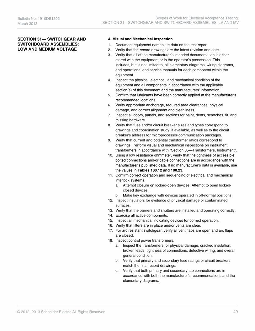
Bulletin No. 1910DB1302 March 2013
49© 2012 -2013 Schneider Electric All Rights Reserved
SECTION 31— SWITCHGEAR AND SWITCHBOARD ASSEMBLIES: LOW AND MEDIUM VOLTAGE
A. Visual and Mechanical Inspection1. Document equipment nameplate data on the test report.2. Verify that the record drawings are the latest revision and date.3. Verify that all of the manufacturer’s intended documentation is either
stored with the equipment or in the operator’s possession. Thisincludes, but is not limited to, all elementary diagrams, wiring diagrams,and operational and service manuals for each component within theequipment.
4. Inspect the physical, electrical, and mechanical condition of theequipment and all components in accordance with the applicablesection(s) of this document and the manufacturers’ information.
5. Confirm that lubricants have been correctly applied at the manufacturer'srecommended locations.
6. Verify appropriate anchorage, required area clearances, physicaldamage, and correct alignment and cleanliness.
7. Inspect all doors, panels, and sections for paint, dents, scratches, fit, andmissing hardware.
8. Verify that fuse and/or circuit breaker sizes and types correspond todrawings and coordination study, if available, as well as to the circuitbreaker's address for microprocessor-communication packages.
9. Verify that current and potential transformer ratios correspond todrawings. Perform visual and mechanical inspections on instrumenttransformers in accordance with “Section 35—Transformers, Instrument”.
10. Using a low resistance ohmmeter, verify that the tightness of accessiblebolted connections and/or cable connections are in accordance with themanufacturer’s published data. If no manufacturer's data is available, usethe values in Tables 100.12 and 100.23.
11. Confirm correct operation and sequencing of electrical and mechanicalinterlock systems.a. Attempt closure on locked-open devices. Attempt to open locked-
closed devices.b. Make key exchange with devices operated in off-normal positions.
12. Inspect insulators for evidence of physical damage or contaminatedsurfaces.
13. Verify that the barriers and shutters are installed and operating correctly.14. Exercise all active components.15. Inspect all mechanical indicating devices for correct operation.16. Verify that filters are in place and/or vents are clear.17. For arc resistant switchgear, verify all vent flaps are open and arc flaps
are closed.18. Inspect control power transformers.
a. Inspect the transformers for physical damage, cracked insulation,broken leads, tightness of connections, defective wiring, and overallgeneral condition.
b. Verify that primary and secondary fuse ratings or circuit breakersmatch the final record drawings.
c. Verify that both primary and secondary tap connections are inaccordance with both the manufacturer's recommendations and theelementary diagrams.
Scopes of Work for Electrical Acceptance Testing: SECTION 31—SWITCHGEAR AND SWITCHBOARD ASSEMBLIES: LV AND MV

50 © 2012 -2013 Schneider Electric All Rights Reserved
19. Set relays in accordance with the coordination study supplied by owner,if available. If a coordination study is not available, the customer will beresponsible for setting relays.
20. Verify that drawout disconnecting and grounding contacts and interlocksfunction correctly.
21. Verify that customer connections to remote power, operators, interlocks,and indicators have been made.
22. When equipped with Arc Flash Maintenance Switch, verify settings andproper operation.
B. Electrical Tests
NOTE: When performing dielectric tests, disconnect all Instrument and Control Transformers, Arresters, TVSS units, and other sensitive electronic equipment that may cause erroneous results or cause damage to equipment that is not rated in accordance with Switchgear or Switchboard industry standards.
1. Perform insulation-resistance tests on each bus section, phase-to-phaseand phase-to-ground, at the minimum dc test voltage appropriate forthe equipment’s Maximum Rated Voltage in accordance with Table100.1. Record the resistances. NOTE: If the resistance is lower than therecommended values in Table 100.1, report it to the owner or projectmanager. It may be possible to dry the equipment using heat and fans.Any initial and low readings should be documented along with any stepsmade to correct the deficiency. If low readings persist, contact themanufacturer.
2. For medium voltage switchgear, perform a dielectric test (Hi-Pot) on eachbus section, each phase to ground with phases not under test grounded,in accordance with Table 100.2 or the manufacturer’s published data.
3. Perform a control wiring performance test by applying control voltage.4. Verify that the equipment operates as intended.5. Perform a phasing check on double-ended switchgear (low voltage) to
insure correct bus phasing from each source. (Optional second visit isrequired if equipment is not energized.)
6. Verify correct function of control power transfer relays located inswitchgear with multiple power sources.
7. When applicable, verify proper operation of Automatic Transfer Schemeand verify Sequence of Operation
8. Verify operation of switchgear/switchboard heaters.9. Test protective relays in accordance with “Section 27—Protective
Relays”.10. Test individual circuit breakers or switches in accordance with the
applicable section of this document.
Scopes of Work for Electrical Acceptance Testing: SECTION 31— SWITCHGEAR AND SWITCHBOARD ASSEMBLIES: LV AND MV
Bulletin No. 1910DB1302 March 2013

Bulletin No. 1910DB1302 March 2013
51© 2012 -2013 Schneider Electric All Rights Reserved
C. Optional Tests1. For low voltage switchgear, Perform a dielectric test (Hi-Pot) on each bus
section, each phase to ground with phases not under test grounded, inaccordance with Table 100.2 or the manufacturer’s published data.NOTE: This test is standard on medium voltage switchgear and optionalon low voltage switchgear and switchboards.
2. Perform tests on all instrument transformers in accordance with “Section35—Transformers, Instrument”.
3. Perform insulation-resistance tests in accordance with Table 100.1 on allcontrol wiring. Do not perform this test on wiring connected to solid-statecomponents.
4. Perform ground-resistance tests in accordance with “Section 22—Grounding Systems”.
5. Perform the following tests on control power transformers.a. Perform insulation-resistance tests. Perform measurements from
winding-to-winding and each winding-to-ground. Test voltages shallbe in accordance with Table 100.1 unless otherwise specified by themanufacturer.
b. Inspect primary winding tab connections and secondary terminalconnections for correct wiring for primary and secondary voltagesinvolved.
c. Perform a secondary wiring integrity test. Disconnect the transformerat secondary terminals and connect secondary wiring to correctsecondary voltage. Confirm potential at all devices.
d. Verify correct secondary voltage by energizing primary winding withsystem voltage. Measure secondary voltage with the secondarywiring disconnected.
6. Perform a contact resistance test through all bus joints, using a lowresistance ohmmeter.
7. Perform the following tests on potential transformers.a. Perform a secondary wiring integrity test. Disconnect transformer
at secondary terminals and connect secondary wiring to correctsecondary voltage. Confirm correct potential at all devices.
b. Verify secondary voltage by energizing primary winding with systemvoltage. Measure secondary voltage with the secondary wiringdisconnected.
8. Perform tests on ground fault protection system in accordance with“Section 20—Ground-Fault Protection Systems”.
9. Perform current tests by primary injection on all metering and relayingcircuits, other than ground fault, in each section of switchgear withmagnitudes, such that a minimum of 1.0 ampere flows in the secondarycircuit. Verify that the secondary current flow at each device is intended inthe current circuit.
10. Determine the accuracy of all meters per “Section 8—Metering”.
Scopes of Work for Electrical Acceptance Testing: SECTION 31—SWITCHGEAR AND SWITCHBOARD ASSEMBLIES: LV AND MV

52 © 2012 -2013 Schneider Electric All Rights Reserved
SECTION 32—SWITCHGEAR DVCAS-38
A. Visual and Mechanical Inspection
1. Document equipment nameplate data on test report. Verify equipmentnameplate ratings are in accordance with the record drawings.
2. Inspect physical and mechanical condition.3. Check all control wiring with the wiring diagrams.4. Verify that all connections are properly made and tightened to the proper
torque values,5. Verify all fuses are installed.6. Verify all current transformer circuits are complete and not shorted.7. Verify all fault detection devices have been properly connected.8. Check all interlocking systems for correct operation and sequencing, and
key distribution, if applicable.9. If any isolating switch is not in operation and is left without incoming
cables, the corresponding grounding switch must be closed and blockedby means of a padlock to avoid possible unintentional operation.
10. Verify appropriate anchorage and required area clearances.11. Verify appropriate equipment grounding.12. Verify that all surfaces are clean and dry.13. Verify that all barriers and covers are secured.14. Operate the grounding switch, isolating switch, circuit breaker and
mechanical interlocks a minimum of five times and verify they arefunctioning properly.
B. Electrical TestsNOTE: When performing dielectric tests, disconnect all Instrument and Control Transformers, Arresters, TVSS units, and other sensitive electronic equipment that may cause erroneous results or be damaged by the applied test voltage. Verify no paths to ground exist with an ohmmeter or initially testing insulation resistance at a low voltage.
1. Perform insulation-resistance tests on each pole, phase-to-phase andphase-to-ground with switch closed and across each open pole for oneminute. Test voltage shall be in accordance with the below table.
2. Perform Hi-Pot test• Disconnect all potential transformer secondary connections or
remove all secondary fuses to isolate the transformer• Short all current transformer secondary terminals or connections.• Apply voltage to each phase individually for one minute with the
other two phases and enclosure grounded. (see below table for Hi-Pot test values)
• Gradually increase voltage.
Hi-Pot Test Values
Equipment Rating
Field Test Voltage
AC DC
38kV 38kV 64kV
Scopes of Work for Electrical Acceptance Testing: SECTION 32—SWITCHGEAR DVCAS-38
Bulletin No. 1910DB1302 March 2013

Bulletin No. 1910DB1302 March 2013
53© 2012 -2013 Schneider Electric All Rights Reserved
SECTION 33—TRANSFORMERS: DRY TYPE: ALL VOLTAGES - LARGE (GREATER THAN 167 SINGLE-PHASE AND 500KVA THREE-PHASE)
A. Visual and Mechanical Inspection
1. Document equipment nameplate data on the test report. Verify thattransformer nameplate ratings are in accordance with the recorddrawings.
2. Inspect the physical and mechanical condition of the equipment.3. Verify that the control and alarm settings on temperature indicators are as
specified, if the settings are available.4. Verify that cooling fans operate correctly and that fan motors have correct
overcurrent protection.5. Using a calibrated torque wrench or low resistance ohmmeter, verify
that the tightness of accessible bolted connections and/or cableconnections are in accordance with the manufacturer’s published data. Ifno manufacturer's data is available, use the values in Tables 100.1 and100.23.
6. Perform specific inspections and mechanical tests as recommended bythe manufacturer.
7. Make a close examination for shipping brackets or fixtures that may nothave been removed during installation. Insure that resilient mounts are free.
8. Verify that winding core, frame, and enclosure groundings are correct.9. Verify that as-left tap connections are as specified.10. Verify that customer connections have been made to remote power and
operators.
B. Electrical TestsNOTE: When performing dielectric tests, disconnect all Instrument and Control Transformers, Arresters, TVSS units, and other sensitive electronic equipment that may cause erroneous results or cause damage to equipment that is not rated in accordance industry standards.
1. Perform insulation-resistance tests winding-to-winding and eachwinding- to-ground, with test voltage in accordance with Table 100.5.Test duration shall be for ten minutes with resistances tabulated at 30seconds, one minute, and ten minutes.
2. Perform a transformer turns-ratio test on all tap connections. Verify thatwinding polarities are in accordance with nameplate.
C. Optional Tests1. For 5kV and above, perform power-factor or dissipation-factor (excitation-
current) tests in accordance with the test equipment manufacturer'sinstructions.
2. Measure the resistance of each winding at each tap connection.3. Verify that the core is grounded. If the core is insulated and a removable
core ground strap is available, perform a core insulation-resistance test at500 volts dc.
Scopes of Work for Electrical Acceptance Testing: SECTION 33—TRANSFORMERS: DRY TYPE: ALL VOLTAGES

54 © 2012 -2013 Schneider Electric All Rights Reserved
SECTION 34—TRANSFORMERS: DRY TYPE - SMALL (167kVA SINGLE-PHASE,500kVA THREE-PHASE, AND SMALLER)
A. Visual and Mechanical Inspection1. Document equipment nameplate data on the test report. Verify that
transformer nameplate ratings are in accordance with record drawings.2. Inspect the physical and mechanical condition of the equipment.3. Verify that resilient mounts are free and that any shipping brackets have
been removed.
B. Electrical TestsNOTE: When performing dielectric tests, disconnect all Instrument and Control Transformers, Arresters, TVSS units, and other sensitive electronic equipment that may cause erroneous results or cause damage to equipment that is not rated in accordance industry standards.
1. Perform an insulation-resistance test. Measurements shall be madefrom winding-to-winding and each winding-to-ground. Test voltages andminimum resistance shall be in accordance with Table 100.5. Resultsshould be temperature corrected in accordance with Table 100.14.
2. Using a TTR, verify that transformer winding turns-ratio measurementsand polarities are in accordance with the nameplate.
3. Verify that as-left tap connections are as specified.
Scopes of Work for Electrical Acceptance Testing: SECTION 34—TRANSFORMERS: DRY TYPE: SINGLE-PHASE, THREE-PHASE
Bulletin No. 1910DB1302 March 2013

Bulletin No. 1910DB1302 March 2013
55© 2012 -2013 Schneider Electric All Rights Reserved
SECTION 35—TRANSFORMERS, INSTRUMENT
A. Visual and Mechanical Inspection1. Verify equipment nameplate ratings are in accordance with the record
drawings.2. Inspect the physical and mechanical condition of the equipment.3. Verify correct connection of transformers with system requirements.4. Verify that adequate clearances exist between primary and secondary
circuit wiring.5. Using a calibrated torque wrench or low resistance ohmmeter, verify that
the tightness of accessible bolted connections and/or cable connectionsare in accordance with the manufacturer’s published data. If nomanufacturer's data is available, use the values in Tables 100.12 and100.23.
6. Verify that all required grounding and shorting connections providecontact.
7. Verify that all shorting blocks are in the correct position, either groundingor open, as required.
8. Verify correct operation of instrument transformer draw-out mechanismsand grounding operation.
9. Verify correct primary and secondary fuse sizes for potentialtransformers.
B. Electrical Tests - Current TransformersRecord the date of the last calibration for each piece of test equipment used.
1. Perform an insulation-resistance test of the current transformer andwiring-to-ground at 500 volts dc. Do not perform this test on solid-statedevices. Resistance readings should be consistent with Table 100.1 for atest voltage of 500 volts dc.
2. Perform a polarity test of each current transformer.3. Perform a ratio-verification test using the voltage or current method
in accordance with ANSI C5XVIII.1 (IEEE Guide for Field Testing ofRelaying Current Transformers).
C. Optional Tests - Current Transformers
1. Perform an excitation test on transformers used for relaying applicationsin accordance with ANSI C5XVIII.1. (IEEE Guide for Field Testing ofRelaying Current Transformers).
2. Measure current circuit burdens at transformer terminals and determinethe total burden.
3. When applicable, perform insulation-resistance and dielectric withstandtests on the primary winding with secondary grounded. Test voltagesshall be in accordance with Table 100.1.
Scopes of Work for Electrical Acceptance Testing: SECTION 35—TRANSFORMERS, INSTRUMENT
56 © 2012 -2013 Schneider Electric All Rights Reserved
D. Electrical Tests - Potential Transformers
Record the date of the last calibration for each piece of test equipment used.
1. Perform insulation-resistance tests winding-to-winding and each winding- to-ground. Test voltages shall be applied for one minute in accordancewith Table 100.1. Do not perform this test with solid-state devicesconnected.
2. Perform a polarity test on each transformer to verify the polarity marks orH1-X1 relationship as applicable.
E. Optional Tests - Potential Transformers1. Measure potential circuit burdens at transformer terminals and determine
the total burden.2. Perform a dielectric withstand test on the primary windings with the
secondary windings connected to ground. The dielectric voltage shall bein accordance with Table 100.9. The test voltage shall be applied for oneminute.
Scopes of Work for Electrical Acceptance Testing: SECTION 35—TRANSFORMERS, INSTRUMENT
Bulletin No. 1910DB1302 March 2013

Bulletin No. 1910DB1302 March 2013
57© 2012 -2013 Schneider Electric All Rights Reserved
SECTION 36—TRANSFORMERS: LIQUID-FILLED: ALL VOLTAGES
A. Visual and Mechanical Inspection
1. Document equipment nameplate data on the test report. Verify thattransformer nameplate ratings are in accordance with the recorddrawings.
2. Inspect the physical and mechanical condition of the equipment.3. Inspect impact recorder prior to unloading, if applicable.4. Verify that alarm, control, and trip settings on temperature indicators are
as specified.5. Verify that cooling fans and pumps operate correctly and that fan and
pump motors have correct overcurrent protection.6. Verify operation of all alarm, control, and trip circuits from temperature
and level indicators, pressure relief device, and fault pressure relay.(Optional second visit if the equipment cannot be energized.)
7. Using a calibrated torque wrench or low resistance ohmmeter, verify thatthe tightness of accessible bolted connections and/or cable connectionsare in accordance with the manufacturer’s published data. If nomanufacturer's data is available, use the values in Tables 100.12 and100.23.
8. Verify correct liquid level in all tanks and bushings.9. Verify that positive pressure is maintained on nitrogen-blanketed
transformers.10. Perform specific inspections and mechanical tests as recommended by
the manufacturer.11. Verify correct equipment grounding.12. Test load tap-changer in accordance with “Section 28—Step Voltage
Regulators”, if applicable.13. Verify removal of any shipping bracing after final placement.
B. Electrical TestsNOTE: When performing dielectric tests, disconnect all Instrument and Control Transformers, Arresters, TVSS units, and other sensitive electronic equipment that may cause erroneous results or cause damage to equipment that is not rated in accordance industry standards.
1. Perform insulation-resistance tests, winding-to-winding, and eachwinding-to-ground with the test voltage in accordance with Table 100.5.Test duration shall be for ten minutes with resistances tabulated at 30seconds, one minute, and ten minutes.
2. Perform a transformer turns-ratio test on all no-load tap-changer positionsand all load tap-changer positions. Verify that tap setting is as specified.Verify that winding polarities are in accordance with nameplate.
Scopes of Work for Electrical Acceptance Testing: SECTION 36—TRANSFORMERS: LIQUID-FILLED: ALL VOLTAGES

58 © 2012 -2013 Schneider Electric All Rights Reserved
C. Optional Tests1. Perform insulation power-factor/dissipation-factor tests on all
windings and correct to 20° C in accordance with the test equipmentmanufacturer's instructions.
2. Perform power-factor/dissipation-factor tests (or hot collar watts-losstests) on bushings and correct for 20° C in accordance with the testequipment manufacturer's instructions.
3. Perform excitation-current tests in accordance with the test equipmentmanufacturer's instructions.
4. Measure the resistance of each winding at each tap connection.5. Remove a sample of insulating liquid in accordance with ASTM D-923.6. The sample shall be tested for the following:
a. Dielectric breakdown voltage: ASTM D-877 and/or ASTM D-1816.b. Acid neutralization number: ASTM D-974.c. (Specific gravity: ASTM D-1298.d. Interfacial tension: ASTM D-971 or ASTM D-2285.e. Color: ASTM D-1500.f. Visual Condition: ASTM D-1524.g. Parts per million water: ASTM D-1533. Required on 25 kV or higher
voltages and on all silicone-filled units.h. Measure dissipation factor or power factor in accordance with ASTM
D-924.7. Remove a sample of insulating liquid in accordance with ASTM D3613
and perform dissolved gas analysis (DGA) in accordance with ANSI/IEEEC5XVI4 or ASTM D-3612.
8. If a core ground strap is accessible, measure the core insulationresistance at 500 Vdc.
9. Measure the insulation resistance of each high-voltage winding in eachno-load tap-changer position. Measure the resistance of each low- voltage winding in each load tap-changer position, if applicable.
Scopes of Work for Electrical Acceptance Testing: SECTION 36—TRANSFORMERS: LIQUID-FILLED: ALL VOLTAGES
Bulletin No. 1910DB1302 March 2013

59© 2012 -2013 Schneider Electric All Rights Reserved
TABLE 100.1
Insulation Resistance Test Values Electrical Apparatus and Systems
Nominal Rating of Equipment in Volts Minimum Test Voltage, DC
Recommended Minimum Insulation Resistance in
Megohms 250 500 25 600 1,000 100
1,000 1,000 100 2,500 1,000 500 5,000 2,500 1,000 8,000 2,500 2,000
15,000 2,500 5,000 25,000 5,000 20,000
34,500 and above 15,000 100,000
In the absence of consensus standards dealing with insulation-resistance tests, the Standards Review Council suggests the above representative values.
See Table 100.14 for temperature correction factors.
Test results are dependent on the temperature of the insulating material and the humidity of the surrounding environment at the time of the test.
Insulation-resistance test data may be used to establish a trending pattern. Deviations from the baseline information permit evaluation of the insulation.
Scopes of Work for Electrical Acceptance Testing: TABLES
Bulletin No. 1910DB1302 March 2013

60 © 2012 -2013 Schneider Electric All Rights Reserved
Table 100.2: Switchgear Withstand Test Voltages (CONT)
Table 100.3: Recommended Dissipation Factor/Power Factor at 20° C Liquid-Filled Transformers, Regulators, and Reactors Acceptance Test Values
TABLE 100.2
Switchgear Withstand Test Voltages
Type of Switchgear Rated Maximum Voltage
(kV) (rms) Maximum Test Voltage kV
AC DC Low-Voltage Power
Circuit Breaker Switchgear
.254/.508/.635 1.6 2.3
Metal-Clad Switchgear
4.76 14 20 8.25 27 37
15.0 27 37
27.0 45 † 38.0 60 †
Station-Type Cubicle Switchgear
15.5 37 †
38.0 60 †
72.5 120 †
Metal Enclosed Interrupter Switchgear
4.76 14 20
8.25 19 27
15.0 27 37
15.5 37 52 25.8 45 †
38.0 60 †
Derived from ANSI/IEEE C37.20.1-1993, Paragraph 5.5, Standard for Metal-Enclosed Low-Voltage Power Circuit- Breaker Switchgear, C37.20.2-1993, Paragraph 5.5, Standard for Metal-Clad and Station-Type Cubicle Switchgear and C37.20.3-1987 (R1992), Paragraph 5.5, Standard for Metal-Enclosed Interrupter Switchgear, and includes 0.75 multiplier with fraction rounded down.
The column headed “DC” is given as a reference only for those using dc tests to verify the integrity of connected cable installations without disconnecting the cables from the switchgear. It represents values believed to be appropriate and approximately equivalent to the corresponding power frequency withstand test values specified for voltage rating of switchgear. The presence of this column in no way implies any requirement for a dc withstand test on ac equipment or that a dc withstand test represents an acceptable alternative to the low-frequency withstand tests specified in these specifications, either for design tests, production tests, conformance tests, or field tests. When making dc tests, the voltage should be raised to the test value in discrete steps and held for a period of one minute.
† Because of the variable voltage distribution encountered when making dc withstand tests, the manufacturer should be contacted for recommendations before applying dc withstand tests to the switchgear. Voltage transformers above 34.5 kV should be disconnected when testing with dc. Refer to ANSI/IEEE C57.13-1993 (IEEE Standard Requirements for Instrument Transformers) paragraph 8.8.2.
Bulletin No. 1910DB1302 March 2013
Scopes of Work for Electrical Acceptance Testing: TABLES
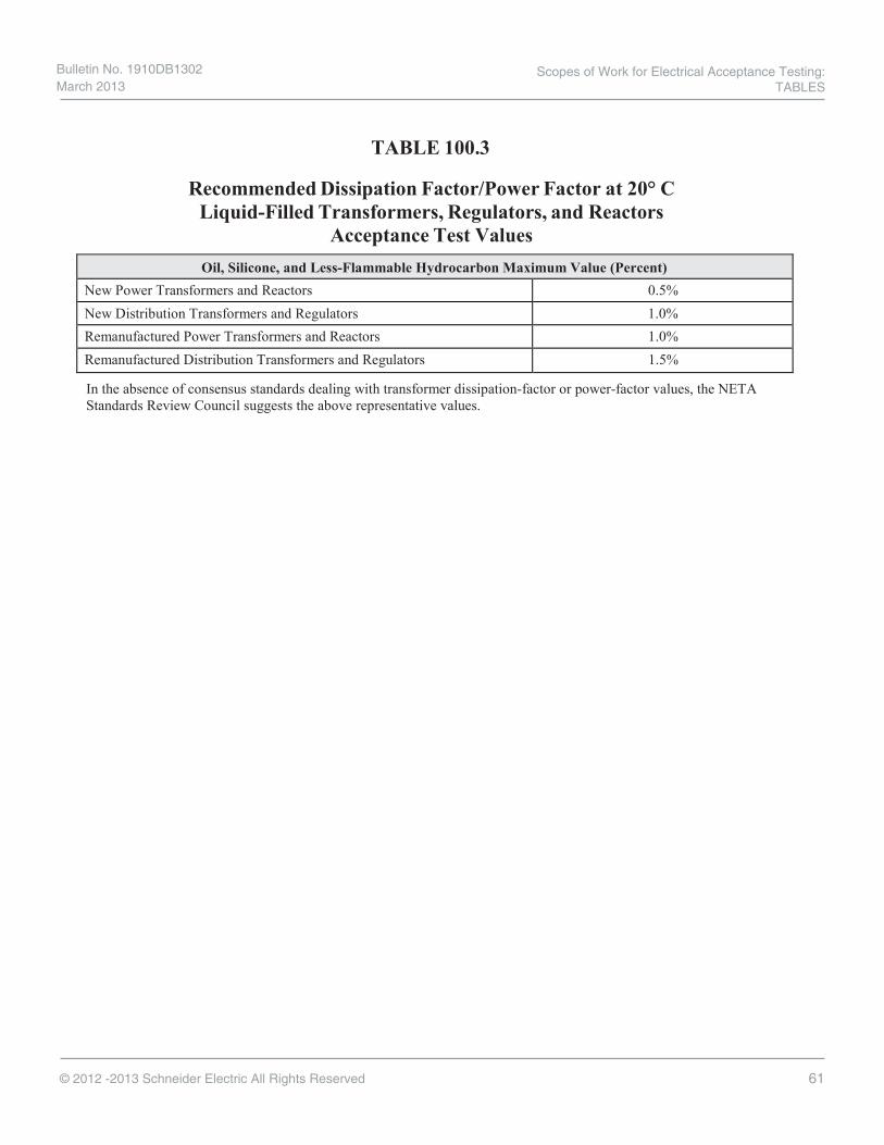
61© 2012 -2013 Schneider Electric All Rights Reserved
TABLE 100.3
Recommended Dissipation Factor/Power Factor at 20° C Liquid-Filled Transformers, Regulators, and Reactors
Acceptance Test Values Oil, Silicone, and Less-Flammable Hydrocarbon Maximum Value (Percent)
New Power Transformers and Reactors 0.5% New Distribution Transformers and Regulators 1.0% Remanufactured Power Transformers and Reactors 1.0% Remanufactured Distribution Transformers and Regulators 1.5%
In the absence of consensus standards dealing with transformer dissipation-factor or power-factor values, the NETA Standards Review Council suggests the above representative values.
Scopes of Work for Electrical Acceptance Testing: TABLES
Bulletin No. 1910DB1302 March 2013

62 © 2012 -2013 Schneider Electric All Rights Reserved
TABLE 100.4
Insulating Fluid Limits Table 100.4.1
Test Limits for New Insulating Oil Received in New Equipment Mineral Oil
Test ASTM Method
d 69 kV and Below
>69 kV - < 230 kV
>230 kV - < 345 kV
>345 kV and Above
Dielectric breakdown, kV minimum D877 30 30 30
Dielectric breakdown, kV minimum @ 1mm (0.04") gap
D1816 25 30 32 35
Dielectric breakdown, kV minimum @ 2 mm (0.08") gap
D1816 45 52 55 60
Interfacial tension mN/m minimum
D971 or D2285 38 38 38 38
Neutralization number, mg KOH/g maximum D974 0.015 0.015 0.015 0.015
Water content, ppm maximum D1533 20 10 10 10
Power factor at 25° C, % D924 0.05 0.05 0.05 0.05 Power factor at 100° C, % D924 0.40 0.40 0.30 0.30 Color D1500 1.0 1.0 1.0 0.5 Visual condition D1524 Bright and clear Bright and clear Bright and clear Bright and clear
ANSI/IEEE C57.106-2002, Guide for Acceptance and Maintenance of Insulating Oil in Equipment, Tables 1, 2, and 3.
Table 100.4.2 Test Limits for Silicone Insulating Liquid in New Transformers
Test ASTM Method Acceptable Values Dielectric breakdown, kV minimum D877 30 Visual D2129 clear, free of particles Water content, ppm maximum D1533 50 Dissipation/power factor, 60 hertz, % max. @ 25° C
D924 0.1
Viscosity, cSt @ 25° C D445 47.5 – 52.5 Fire point, ° C, minimum D92 340 Neutralization number, mg KOH/g max.
D974 0.01
ANSI/IEEE C57.111-1989 (R1995), Guide for Acceptance of Silicone Insulating Fluid and Its Maintenance in Transformers, Table 2.
Bulletin No. 1910DB1302 March 2013
Scopes of Work for Electrical Acceptance Testing: TABLES

63© 2012 -2013 Schneider Electric All Rights Reserved
TABLE 100.4 (continued)
Insulating Fluid Limits Table 100.4.3
Typical Values for Less-Flammable Hydrocarbon Insulating Liquid Received in New Equipment
ASTM Method Test
Results
Minimum Maximum
D1816 Dielectric breakdown voltage for 0.08 in gap, kV 40 34.5 kV class and below
----- 50 Above 34.5 kV class 60 Desirable
D1816 Dielectric breakdown voltage for 0.04 in gap kV 20 34.5 kV class and below
----- 25 Above 34.5 kV class 30 Desirable
D974 Neutralization number, mg KOH/g ----- 0.03 D877 Dielectric breakdown voltage Kv 30 -----
D924 AC loss characteristic (dissipation factor), % 25° C 100° C
----- -----
0.1 1
D1533B Water content, ppm ----- 25 D1524 Condition-visual Clear D92 Flash point (° C) 275 ----- D92 Fire point (° C) 300a
----- D971 Interfacial tension, mN/m, 25° C 38 ----- D445 Kinematic viscosity, mm2/s, (cSt), 40° C 1.0 X 10² (100) 1.3 X 10² (130) D1500 Color ----- L2.5
ANSI/IEEE C57.121-1998, IEEE Guide for Acceptance and Maintenance of Less Flammable Hydrocarbon Fluid in Transformers, Table 3.
The test limits shown in this table apply to less-flammable hydrocarbon fluids as a class. Specific typical values for each brand of fluid should be obtained from each fluid manufacturer.
a. If the purpose of the HMWH installation is to comply with the NFPA 70 National Electrical Code, this value is theminimum for compliance with NEC Article 450.23.
Scopes of Work for Electrical Acceptance Testing: TABLES
Bulletin No. 1910DB1302 March 2013

64 © 2012 -2013 Schneider Electric All Rights Reserved
TABLE 100.5
Transformer Insulation Resistance Acceptance Testing
Transformer Coil Rating Type in Volts
Minimum DC Test Voltage
Recommended Minimum Insulation Resistance in Megohms
Liquid Filled Dry 0 - 600 1000 100 500 601 - 5000 2500 1000 5000 Greater than 5000 5000 5000 25000
In the absence of consensus standards, the NETA Standards Review Council suggests the above representative values.
See Table 100.14 for temperature correction factors.
NOTE: Since insulation resistance depends on insulation rating (kV) and winding capacity (kVA), values obtained should be compared to manufacturer’s published data.
Bulletin No. 1910DB1302 March 2013
Scopes of Work for Electrical Acceptance Testing: TABLES

65© 2012 -2013 Schneider Electric All Rights Reserved
TABLE 100.6
Medium-Voltage Cables Acceptance Test Values
Table 100.6.1 DC Test Voltages
Rated Voltage Phase-to-Phase
kV Conductor Size
AWG or kcmil (mm)
Nominal Insulation Thickness mils (mm)
Maximum DC Field Test Voltages, kV
During/After Installation
100% Insulation
Level
133% Insulation
Level
100% Insulation
Level
133% Insulation
Level
5 8-1000 (8.4-507) Above 1000 (507)
90 (2.29) 140 (3.56)
115 (2.92) 140 (3.56)
28 28
36 36
8 6-1000 (13.3-507) Above 1000 (507)
115 (2.92) 175 (4.45)
140 (3.56) 175 (4.45)
36 36
44 44
15 2-1000 (33.6-507) Above 1000 (507)
175 (4.45) 220 (5.59)
220 (5.59) 220 (5.59)
56 56
64 64
25 1-2000 (42.4-1013) 260 (6.60) 320 (8.13) 80 96 28 1-2000 (42.4-1013) 280 (7.11) 345 (8.76) 84 100 35 1/0-2000 (53.5-1013) 345 (8.76) 420 (10.7) 100 124 46 4/0-2000 (107.2-1013) 445 (11.3) 580 (14.7) 132 172 69 4/0-2000 (107.2-1013) ---- 650 ---- 195
Tables derived from ANSI/ICEA S 93-639/NEMA WC 74-2000, 5-46 kV Shielded Power Cable for Use in the Transmission and Distribution of Electric Energy; ANSI/ICEA S-94-649-2000, Standard for Concentric Neutral Cables Rated 5,000 - 46,000 Volts; ANSI/ICEA S-97-682-2000, Standard for Utility Shielded Power Cables Rated 5,000 - 46,000 Volts; and The Okonite Company, High-Voltage Proof Testing.
DC test voltages are applied to discover gross problems such as incorrectly installed accessories or mechanical damage.
The dc field test voltages listed above are intended for cable designed in accordance with ICEA specifications. When older cables or other types/classes of cables or accessories are connected to the system, voltages lower than those shown may be necessary. Consult the manufacturers of the cables and accessories before applying the test voltage.
Scopes of Work for Electrical Acceptance Testing: TABLES
Bulletin No. 1910DB1302 March 2013

Bulletin No. 1910DB1302 March 2013
66 © 2012 -2013 Schneider Electric All Rights Reserved
Scopes of Work for Electrical Acceptance Testing: TABLES
TABLE 100.6 (continued)
Medium-Voltage Cables Acceptance Test Values
Table 100.6.2 AC Test Voltages
Rated Voltage Phase-to-Phase
kV Conductor Size AWG or kcmil
Nominal Insulation Thickness Mils (mm)
AC Test Voltage, kV
100% Insulation
Level
133% Insulation
Level
100% Insulation
Level
133% Insulation
Level
5 kV 8-1000 1001-3000
90 (2.29) 140 (3.56)
115 (2.92) 140 (3.56)
18 28
23 28
8 kV 6-1000 1001-3000
115 (2.92) 175 (4.45)
140 (3.56) 175 (4.45)
23 35
28 35
15 kV 2-1000 1001-3000
175 (4.45) 220 (5.59)
220 (5.59) 220 (5.59)
35 44
44 44
25 kV 1-3000 260 (6.60) 320 (8.13) 52 64
28 kV 1-3000 280 (7.11) 345 (8.76) 56 69
35 kV 1/0-3000 345 (8.76) 420 (10.7) 69 84
46 kV 4/0-3000 445 (11.3) 580 (14.7) 89 116
Tables derived from ANSI/ICEA S 93-639/NEMA WC 74-2000, 5-46 kV Shielded Power Cable for Use in the Transmission and Distribution of Electric Energy; ANSI/ICEA S-94-649-2000, Standard for Concentric Neutral Cables Rated 5,000 - 46,000 Volts; ANSI/ICEA S-97-682-2000, Standard for Utility Shielded Power Cables Rated 5,000 - 46,000 Volts.
All ac voltages are rms values.

67© 2012 -2013 Schneider Electric All Rights Reserved
TABLE 100.6 (continued)
Medium-Voltage Cables Acceptance Test Values
Table 100.6.3 Partial Discharge Requirements for Semiconduction Coating and Semiconducting, Nonmetalic Tape
Designs Only
Rated Circuit Voltage Phase-to-Phase Volts Minimum Partial Discharge Extinction Level, kV
100% Insulation Level 133% Insulation Level 2001-5000 4 5 5001-8000 6 8 8001-15000 11 15
In the absence of consensus standards the NETA Standards Review Council suggests the above representative values.
ANSI/ICEA S 93-639/NEMA WC 74-2000, 5-46 kV Shielded Power Cable for Use in the Transmission and Distribution of Electric Energy.
Table 100.6.4 Very Low Frequency Testing Levels
0.1 Hz Test Voltage (rms)
System Voltage Phase-to-Phase
(kV) (rms)
Proof Phase-to-Ground
(kV) (rms)
5 10
15 22
25 33
35 47
In the absence of consensus standards the NETA Standards Review Council suggests the above representative values.
Scopes of Work for Electrical Acceptance Testing: TABLES
Bulletin No. 1910DB1302 March 2013

68 © 2012 -2013 Schneider Electric All Rights Reserved
TABLE 100. 7
Inverse Time Trip Test at 300% of Rated Continuous Current of Circuit Breaker
Molded-Case Circuit Breakers
Range of Rated Continuous Current (Amperes)
Maximum Trip Time in Seconds For Each Maximum Frame Ratinga
< 250 V 251 – 600V 0-30 50 70
31-50 80 100 51-100 140 160
101-150 200 250 151-225 230 275 226-400 300 350 401-600 ---- 450 601-800 ---- 500
801-1000 ---- 600 1001 – 1200 ---- 700 1201-1600 ---- 775 1601-2000 ---- 800 2001-2500 ---- 850 2501-5000 ---- 900
6000 ---- 1000
Derived from Table 5-3, NEMA Standard AB 4-1996, Guidelines for Inspection and Preventive Maintenance of Molded- Case Circuit Breakers Used in Commercial and Industrial Applications.
a. Trip times may be substantially longer for integrally-fused circuit breakers if tested with the fuses replaced by solidlinks (shorting bars).
Bulletin No. 1910DB1302 March 2013
Scopes of Work for Electrical Acceptance Testing: TABLES

69© 2012 -2013 Schneider Electric All Rights Reserved
TABLE 100.8
Instantaneous Trip Tolerances for Field Testing of Circuit Breakers
Tolerances of Manufacturer’s Published Trip Range
Breaker Type Tolerance of Settings High Side Low Side
Adjustable +40% -30%
---- ----
Nonadjustable ---- +25% -25%
Reproduction of Table 5-4 from NEMA publication AB4-1996.
For circuit breakers with nonadjustable instantaneous trips, tolerances apply to the manufacturer’s published trip range, i.e., +40 percent on high side, -30 percent on low side.
Scopes of Work for Electrical Acceptance Testing: TABLES
Bulletin No. 1910DB1302 March 2013

70 © 2012 -2013 Schneider Electric All Rights Reserved
TABLE 100.9 Instrument Transformer Dielectric Tests
Field Acceptance
Nominal System Voltage (kV)
BIL (kV)
Periodic Dielectric Withstand Test Field Test Voltage (kV)
AC DC* 0.60 10 3.0 4 1.20 30 7.5 10 2.40 45 11.25 15 5.00 60 14.25 19 8.70 75 19.5 26
15.00 95 25.5 34 15.00 110 25.5 34 25.00 125 30.0 40 25.00 150 37.5 50 34.50 200 52.5 70 46.00 250 71.2 + 69.00 350 105 +
115.00 450 138 + 115.00 550 172 + 138.00 650 206 + 161.00 750 243 + 230.00 900 296 + 230.00 1050 345 + 345.00 1300 431 + 500.00 1675 562 + 500.00 1800 600 + 765.00 2050 690 +
Table 100.9 is derived from Paragraph 8.8.2 and Tables 2 of ANSI/IEEE C57.13-1993, Standard Requirements for Instrument Transformers.
+ Periodic dc potential tests are not recommended for transformers rated higher than 34.5 kV.
* DC potential tests are not recommended for transformers rated higher than 200 kV BIL. DC tests may provebeneficial as a reference for future testing. In such cases the test direct voltage shall not exceed the original factorytest rms alternating voltages.
Bulletin No. 1910DB1302 March 2013
Scopes of Work for Electrical Acceptance Testing: TABLES
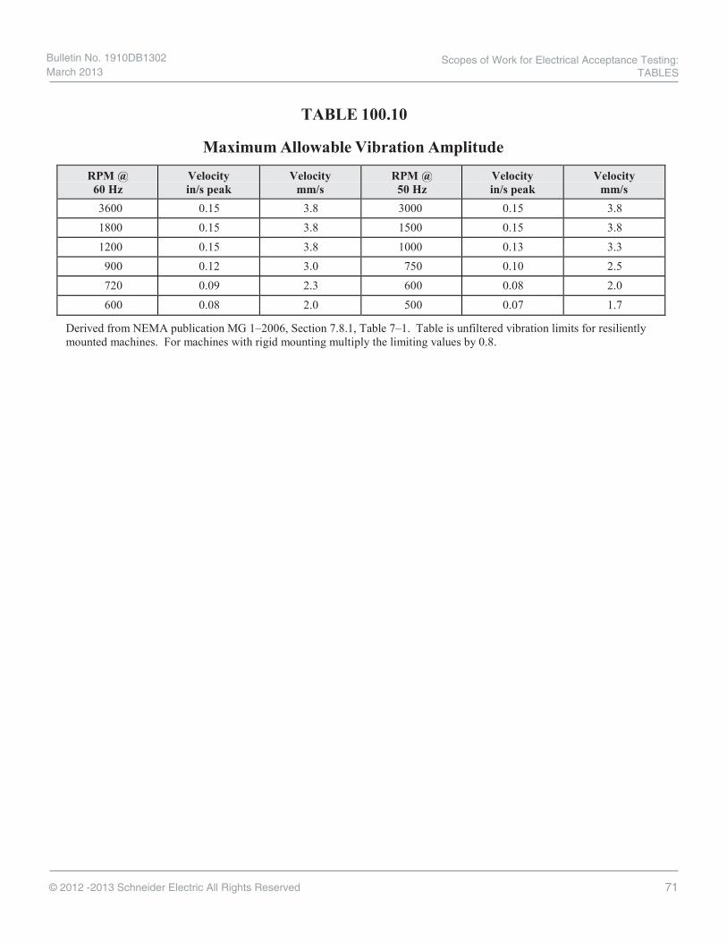
71© 2012 -2013 Schneider Electric All Rights Reserved
TABLE 100.10
Maximum Allowable Vibration Amplitude
RPM @ 60 Hz
Velocity in/s peak
Velocity mm/s
RPM @ 50 Hz
Velocity in/s peak
Velocity mm/s
3600 0.15 3.8 3000 0.15 3.8 1800 0.15 3.8 1500 0.15 3.8 1200 0.15 3.8 1000 0.13 3.3 900 0.12 3.0 750 0.10 2.5 720 0.09 2.3 600 0.08 2.0 600 0.08 2.0 500 0.07 1.7
Derived from NEMA publication MG 1–2006, Section 7.8.1, Table 7–1. Table is unfiltered vibration limits for resiliently mounted machines. For machines with rigid mounting multiply the limiting values by 0.8.
Scopes of Work for Electrical Acceptance Testing: TABLES
Bulletin No. 1910DB1302 March 2013

72 © 2012 -2013 Schneider Electric All Rights Reserved
TABLE 100.11
— RESERVED —
Bulletin No. 1910DB1302 March 2013
Scopes of Work for Electrical Acceptance Testing: TABLES

73 © 2012 -2013 Schneider Electric All Rights Reserved
TABLE 100.12.1
Bolt-Torque Values for Electrical Connections
US Standard Fasteners aHeat-Treated Steel – Cadmium or Zinc Plated b
Grade SAE 1&2 SAE 5 SAE 7 SAE 8
Head Marking
Minimum Tensile (Strength) (lbf/in2)
64k 105k 133k 150k
Bolt Diameter (Inches)
Torque (Pound-Feet)
1/4 4 6 8 8 5/16 7 11 15 18 3/8 12 20 27 30 7/16 19 32 44 48 1/2 30 48 68 74 9/16 42 70 96 105 5/8 59 96 135 145 3/4 96 160 225 235 7/8 150 240 350 380 1.0 225 370 530 570
a. Consult manufacturer for equipment supplied with metric fasteners.
b. Table is based on national coarse thread pitch.
Scopes of Work for Electrical Acceptance Testing: TABLES
Bulletin No. 1910DB1302 March 2013

74© 2012 -2013 Schneider Electric All Rights Reserved
TABLE 100.12.2
US Standard Fasteners a
Silicon Bronze Fasteners b c
Torque (Pound-Feet) Bolt Diameter (Inches) Nonlubricated Lubricated
5/16 15 10 3/8 20 15 1/2 40 25 5/8 55 40 3/4 70 60
a. Consult manufacturer for equipment supplied with metric fasteners.
b. Table is based on national coarse thread pitch.
c. This table is based on bronze alloy bolts having a minimum tensile strength of 70,000 pounds per square inch.
TABLE 100.12.3
US Standard Fasteners a
Aluminum Alloy Fasteners b c
Torque (Pound-Feet) Bolt Diameter (Inches) Lubricated
5/16 10
3/8 14
1/2 25
5/8 40
3/4 60
a. Consult manufacturer for equipment supplied with metric fasteners.b. Table is based on national coarse thread pitch.c. This table is based on aluminum alloy bolts having a minimum tensile strength of 55,000 pounds per
square inch.
Bulletin No. 1910DB1302 March 2013
Scopes of Work for Electrical Acceptance Testing: TABLES
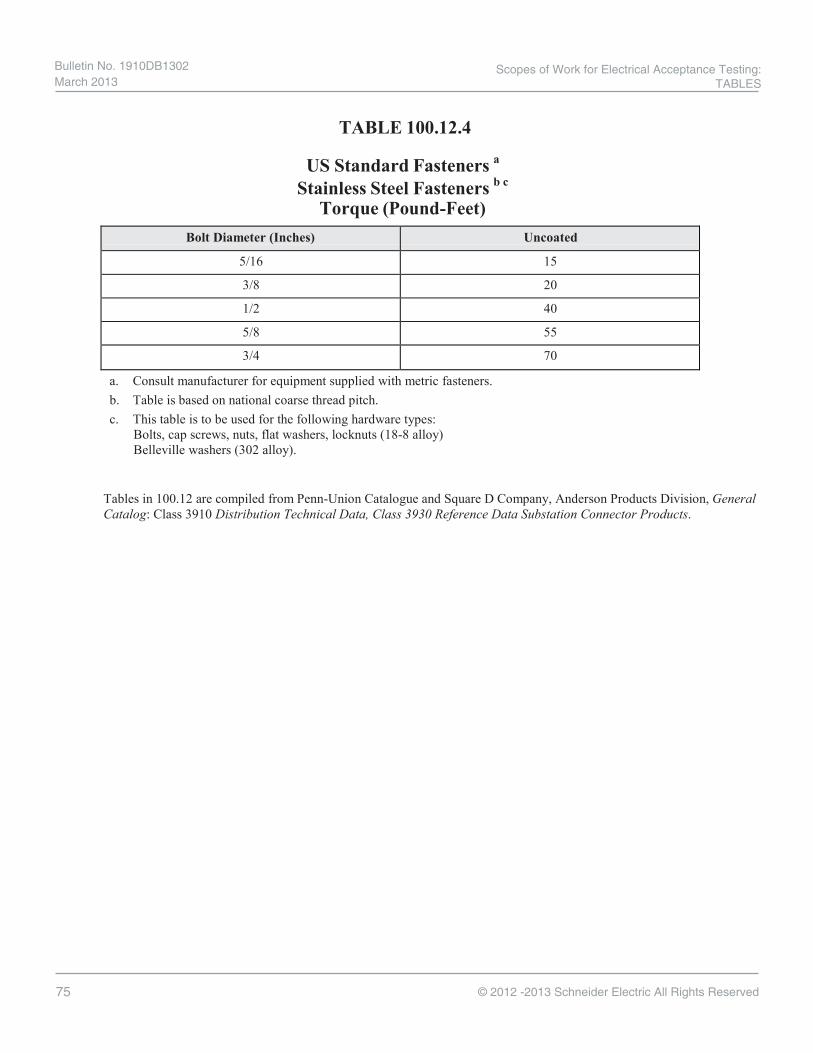
75 © 2012 -2013 Schneider Electric All Rights Reserved
TABLE 100.12.4
US Standard Fasteners a
Stainless Steel Fasteners b c
Torque (Pound-Feet) Bolt Diameter (Inches) Uncoated
5/16 15
3/8 20
1/2 40
5/8 55
3/4 70
a. Consult manufacturer for equipment supplied with metric fasteners.b. Table is based on national coarse thread pitch.c. This table is to be used for the following hardware types:
Bolts, cap screws, nuts, flat washers, locknuts (18-8 alloy)Belleville washers (302 alloy).
Tables in 100.12 are compiled from Penn-Union Catalogue and Square D Company, Anderson Products Division, General Catalog: Class 3910 Distribution Technical Data, Class 3930 Reference Data Substation Connector Products.
Scopes of Work for Electrical Acceptance Testing: TABLES
TABLES
Bulletin No. 1910DB1302 March 2013

76© 2012 -2013 Schneider Electric All Rights Reserved
TABLE 100.13
SF6 Gas Tests Test Method Serviceability Limits a
Moisture Hygrometer Per manufacturer or t 200 ppmb
SF6 decomposition byproducts ASTM D 2685 t 500 ppm Air ASTM D 2685 t 5000 ppmc
Dielectric breakdown hemispherical contacts 0.10 inch gap at atmospheric pressure 11.5 - 13.5 kVd
a. In the absence of consensus standards dealing with SF6 circuit breaker gas tests, the NETA Standards Review Councilsuggests the above representative values.
b. According to some manufacturers.c. Dominelli, N. and Wylie, L., Analysis of SF6 Gas as a Diagnostic Technique for GIS, Electric Power Research
Institute, Substation Equipment Diagnostics Conference IV, February 1996.d. Per Even, F.E., and Mani, G. Sulfur Fluorides, Kirk, Othmer Encyclopedia of Chemical Technology, 4th ed., 11,428,
1994. Reference: IEC 61634 High-Voltage Switchgear and Controlgear - Use and Handling of Sulfur Hexafluoride (SF6) inHigh-Voltage Switchgear and Controlgear.
Bulletin No. 1910DB1302 March 2013
Scopes of Work for Electrical Acceptance Testing: TABLES

77 © 2012 -2013 Schneider Electric All Rights Reserved
TABLE 100.14
Insulation Resistance Conversion Factors (20° C)
Table 100.14.1 Test Temperatures to 20° C
Temperature Multiplier
° C ° F Apparatus Containing Immersed Oil Insulation
Apparatus Containing Solid Insulation
-10 14 0.125 0.25 -5 23 0.180 0.32 0 32 0.25 0.40 5 41 0.36 0.50
10 50 0.50 0.63 15 59 0.75 0.81 20 68 1.00 1.00 25 77 1.40 1.25 30 86 1.98 1.58 35 95 2.80 2.00 40 104 3.95 2.50 45 113 5.60 3.15 50 122 7.85 3.98 55 131 11.20 5.00 60 140 15.85 6.30 65 149 22.40 7.90 70 158 31.75 10.00 75 167 44.70 12.60 80 176 63.50 15.80 85 185 89.789 20.00 90 194 127.00 25.20 95 203 180.00 31.60
100 212 254.00 40.00 105 221 359.15 50.40 110 230 509.00 63.20
Derived from Stitch in Time…The Complete Guide to Electrical Insulation Testing, Megger.
Formula: Rc = Ra x K Where: Rc
Ra
K
is resistance corrected to 20° C is measured resistance at test temperature is applicable multiplier
Example: Resistance test on oil-immersion insulation at 104° Ra = 2 megohms @ 104° F K = 3.95 Rc = Ra x K Rc = 2.0 x 3.95 Rc = 7.90 megohms @ 20° C
Scopes of Work for Electrical Acceptance Testing: TABLES
Bulletin No. 1910DB1302 March 2013

78© 2012 -2013 Schneider Electric All Rights Reserved
TABLE 100.14 (continued)
Insulation Resistance Conversion Factors (40° C)
Table 100.14.2 Test Temperature to 40° C
Temperature Multiplier
° C ° F Apparatus Containing
Immersed Oil Insulation Apparatus Containing
Solid Insulation -10 14 0.03 0.10
-5 23 0.04 0.13 0 32 0.06 0.16 5 41 0.09 0.20
10 50 0.13 0.25 15 59 0.18 0.31 20 68 0.25 0.40 25 77 0.35 0.50 30 86 0.50 0.63 35 95 0.71 0.79 40 104 1.00 1.00 45 113 1.41 1.26 50 122 2.00 1.59 55 131 2.83 2.00 60 140 4.00 2.52 65 149 5.66 3.17 70 158 8.00 4.00 75 167 11.31 5.04 80 176 16.00 6.35 85 185 22.63 8.00 90 194 32.00 10.08 95 203 45.25 12.70
100 212 64.00 16.00 105 221 90.51 20.16 110 230 128.00 25.40
Derived from Megger’s Stitch in Time…The Complete Guide to Electrical Insulation Testing and ANSI/IEEE 43-2000, IEEE Recommended Practice for Testing Insulation Resistance of Rotating Machinery. Notes: The insulation resistance coefficient is based on the halving of the insulation resistance to the change in temperature.
Apparatus Containing Immersed Oil Insulation Table uses 10° C change with temperature halving. Apparatus Containing Solid Insulation Table uses 15° C change with temperature halving.
Formula: Rc = Ra x K Where: Rc is resistance corrected to 40° C
Ra is measured resistance at test temperature K is applicable multiplier
Example: Resistance test on oil-immersion insulation at 68° F/20° C
Ra = 2 megohms @ 68° F/20° C K = 0.40 Rc = Ra x K Rc = 2.0 x 0.40 = 0.8 megohms @ 40° C
Bulletin No. 1910DB1302 March 2013
Scopes of Work for Electrical Acceptance Testing: TABLES
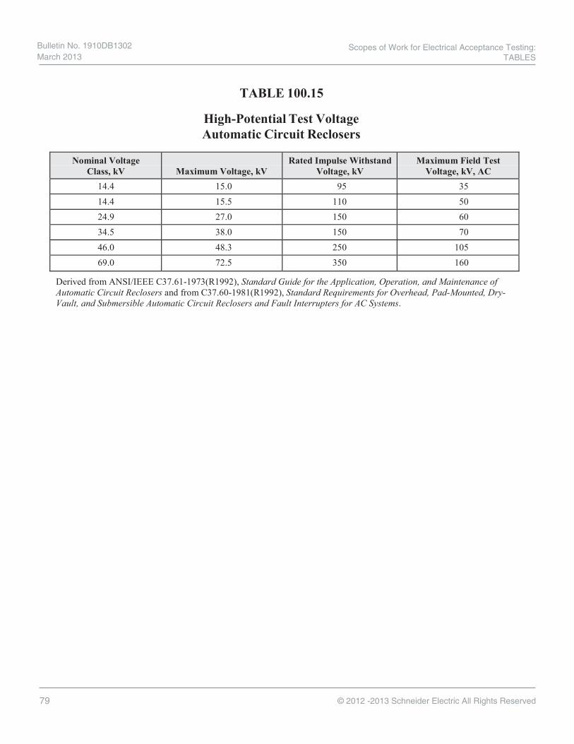
79 © 2012 -2013 Schneider Electric All Rights Reserved
TABLE 100.15
High-Potential Test Voltage Automatic Circuit Reclosers
Nominal Voltage Class, kV Maximum Voltage, kV
Rated Impulse Withstand Voltage, kV
Maximum Field Test Voltage, kV, AC
14.4 15.0 95 35 14.4 15.5 110 50 24.9 27.0 150 60 34.5 38.0 150 70 46.0 48.3 250 105 69.0 72.5 350 160
Derived from ANSI/IEEE C37.61-1973(R1992), Standard Guide for the Application, Operation, and Maintenance of Automatic Circuit Reclosers and from C37.60-1981(R1992), Standard Requirements for Overhead, Pad-Mounted, Dry- Vault, and Submersible Automatic Circuit Reclosers and Fault Interrupters for AC Systems.
Scopes of Work for Electrical Acceptance Testing: TABLES
Bulletin No. 1910DB1302 March 2013

80© 2012 -2013 Schneider Electric All Rights Reserved
TABLE 100.16
High-Potential Test Voltage for Acceptance Testing of Line Sectionalizers
Nominal Voltage Class kV
Maximum Voltage kV
Rated Impulse Withstand Voltage
kV Maximum Field Test
Voltage kV, AC DC 15 Minute
Withstand (kV) 14.4 (1 ø) 15.0 95 35 53 14.4 (1 ø) 15.0 125 42 53 14.4 (3 ø) 15.5 110 50 53 24.9 (1 ø) 27.0 125 60 78 34.5 (3 ø) 38.0 150 70 103
Derived from ANSI/IEEE C37.63-1984(R1990) Table 2 (Standard Requirements for Overhead, Pad-Mounted, Dry- Vault, and Submersible Automatic Line Sectionalizers of ac Systems).
In the absence of consensus standards, the NETA Standards Review Council suggests the above representative values.
NOTE: Values of ac voltage given are dry test one minute factory test values.
Bulletin No. 1910DB1302 March 2013
Scopes of Work for Electrical Acceptance Testing: TABLES

81 © 2012 -2013 Schneider Electric All Rights Reserved
Type of Bus Rated kV Maximum Test Voltage, kV
AC DC
Isolated Phase for Generator Leads 24.5 29.5 34.5
37.0 45.0 60.0
52.0 --- ---
Isolated Phase for Other than Generator Leads
15.5 25.8 38.0
37.0 45.0 60.0
52.0 ------
Nonsegregated Phase
0.635 4.76 15.0 25.8 38.0
1.6 14.2 27.0 45.0 60.0
2.3 20.0 37.0 63.0
---
Segregated Phase 15.5 25.8 38.0
37.0 45.0 60.0
52.0 63.0
-- -
DC Bus Duct
0.3 0.8 1.2 1.6 3.2
1.6 2.7 3.4 4.0 6.6
2.3 3.9 4.8 5.7 9.3
Derived from ANSI/IEEE C37.23-1987, Tables 3A, 3B, 3C, 3D and paragraph 6.4.2. The table includes a 0.75 multiplier with fractions rounded down.
NOTE:
The presence of the column headed “DC” does not imply any requirement for a dc withstand test on ac equipment. This column is given as a reference only for those using dc tests and represents values believed to be appropriate and approximately equivalent to the corresponding power frequency withstand test values specified for each class of bus.
Direct current withstand tests are recommended for flexible bus to avoid the loss of insulation life that may result from the dielectric heating that occurs with rated frequency withstand testing.
Because of the variable voltage distribution encountered when making dc withstand tests and variances in leakage currents associated with various insulation systems, the manufacturer should be consulted for recommendations before applying dc withstand tests to this equipment.
TABLE 100.17
Dielectric Withstand Test Voltages Metal-Enclosed Bus
Scopes of Work for Electrical Acceptance Testing: TABLES
Bulletin No. 1910DB1302 March 2013

82© 2012 -2013 Schneider Electric All Rights Reserved
Thermographic Survey Suggested Actions Based on Temperature Rise
Temperature difference ('T) based on comparisons between similar
components under similar loading.
Temperature difference ('T) based upon comparisons between component and ambient air
temperatures. Recommended Action
1ºC - 3ºC 1ºC - 10ºC Possible deficiency; warrants investigation
4ºC - 15ºC 11ºC - 20ºC Indicates probable deficiency; repair as time permits
---- 21ºC - 40ºC Monitor until corrective measures can be accomplished
>15ºC >40ºC Major discrepancy; repair immediately
Temperature specifications vary depending on the exact type of equipment. Even in the same class of equipment (i.e., cables) there are various temperature ratings. Heating is generally related to the square of the current; therefore, the load current will have a major impact on 'T. In the absence of consensus standards for 'T, the values in this table will provide reasonable guidelines.
An alternative method of evaluation is the standards-based temperature rating system as discussed in Chapter 8.9.2, Conducting an IR Thermographic Inspection, Electrical Power Systems Maintenance and Testing, by Paul Gill, PE, 1998.
It is a necessary and valid requirement that the person performing the electrical inspection be thoroughly trained and experienced concerning the apparatus and systems being evaluated as well as knowledgeable of thermographic methodology.
TABLE 100.18
Bulletin No. 1910DB1302 March 2013
Scopes of Work for Electrical Acceptance Testing: TABLES

83 © 2012 -2013 Schneider Electric All Rights Reserved
Nominal System (Line) Voltagea (kV)
Insulation Class
AC Factory Test (kV)
Maximum Field Applied AC Test (kV)
Maximum Field Applied DC Test (kV)
1.2 1.2 10 6.0 8.5 2.4 2.5 15 9.0 12.7 4.8 5.0 19 11.4 16.1 8.3 8.7 26 15.6 22.1
14.4 15.0 34 20.4 28.8 18.0 18.0 40 24.0 33.9 25.0 25.0 50 30.0 42.4 34.5 35.0 70 42.0 59.4 46.0 46.0 95 57.0 80.6 69.0 69.0 140 84.0 118.8
In the absence of consensus standards, the NETA Standards Review Council suggests the above representative values.
a. Intermediate voltage ratings are placed in the next higher insulation class.
TABLE 100.19 Dielectric Withstand Test Voltages
Electrical Apparatus Other than Inductive Equipment
Scopes of Work for Electrical Acceptance Testing: TABLES
Bulletin No. 1910DB1302 March 2013

84© 2012 -2013 Schneider Electric All Rights Reserved
Rated Control Voltages and their Ranges for Circuit Breakers Operating mechanisms are designed for rated control voltages listed with operational capability throughout the indicated voltage ranges to accommodate variations in source regulation, coupled with low charge levels, as well as high charge levels maintained with floating charges. The maximum voltage is measured at the point of user connection to the circuit breaker [see notes (12) and (13)] with no operating current flowing, and the minimum voltage is measured with maximum operating current flowing.
100.20.1 Rated Control Voltages and their Ranges for Circuit Breakers
(11) Rated Control Voltage
Direct Current Voltage Ranges (1)(2)(3)(5)
Volts, dc (8)(9)
Opening Functions All Types
Rated Control Voltage (60 Hz)
Alternating Current Voltage Ranges (1)(2)(3)(4)(8)
Closing, Tripping, and Auxiliary Functions
Closing and Auxiliary Functions
Indoor Circuit Breakers
Outdoor Circuit
Breakers Single Phase Single Phase 24 (6) 48 (6) 125 250 --- ---
--- 38–56
100–140 200–280
--- ---
--- 36–56 90–140
180–280 --- ---
14–28 28–56
70–140 140–280
--- ---
120 240 ---
104–127 (7) 208–254 (7) ---
Polyphase Polyphase 208Y/120
240 180Y/104–220Y/127
208–254
Derived from Table 8, ANSI C37.06-2000, AC High-Voltage Circuit Breakers Rated on a Symmetrical Current Basis — Preferred Ratings and Related Required Capabilities.
Notes: (1) Electrically operated motors, contactors, solenoids, valves, and the like, need not carry a nameplate voltage rating that
corresponds to the control voltage rating shown in the table as long as these components perform the intended duty cycle (usually intermittent) in the voltage range specified.
(2) Relays, motors, or other auxiliary equipment that function as a part of the control for a device shall be subject to the voltage limits imposed by this standard, whether mounted at the device or at a remote location.
(3) Circuit breaker devices, in some applications, may be exposed to control voltages exceeding those specified here due to abnormal conditions such as abrupt changes in line loading. Such applications require specific study, and the manufacturer should be consulted. Also, application of switchgear devices containing solid-state control, exposed continuously to control voltages approaching the upper limits of ranges specified herein, require specific attention and the manufacturer should be consulted before application is made.
(4) Includes supply for pump or compressor motors. Note that rated voltages for motors and their operating ranges are covered by ANSI/NEMA MG-1-1978.
(5) It is recommended that the coils of closing, auxiliary, and tripping devices that are connected continually to one dc potential should be connected to the negative control bus so as to minimize electrolytic deterioration.
(6) 24-volt or 48-volt tripping, closing, and auxiliary functions are recommended only when the device is located near the battery or where special effort is made to ensure the adequacy of conductors between battery and control terminals. 24-volt closing is not recommended.
(7) Includes heater circuits
TABLE 100.20
Bulletin No. 1910DB1302 March 2013
Scopes of Work for Electrical Acceptance Testing: TABLES

85 © 2012 -2013 Schneider Electric All Rights Reserved
Rated Control Voltages and their Ranges for Circuit Breakers (8) Voltage ranges apply to all closing and auxiliary devices when cold. Breakers utilizing standard auxiliary relays for
control functions may not comply at lower extremes of voltage ranges when relay coils are hot, as after repeated or continuous operation.
(9) Direct current control voltage sources, such as those derived from rectified alternating current, may contain sufficient inherent ripple to modify the operation of control devices to the extent that they may not function over the entire specified voltage ranges
(10) This table also applies for circuit breakers in gas insulated substation installations. (11) In cases where other operational ratings are a function of the specific control voltage applied, tests in C37.09 may
refer to the “Rated Control Voltage.” In these cases, tests shall be performed at the levels in this column. (12) For an outdoor circuit breaker, the point of user connection to the circuit breaker is the secondary terminal block point
at which the wires from the circuit breaker operating mechanism components are connected to the user’s control circuit wiring.
(13) For an indoor circuit breaker, the point of user connection to the circuit breaker is either the secondary disconnecting contact (where the control power is connected from the stationary housing to the removable circuit breaker) or the terminal block point in the housing nearest to the secondary disconnecting contact.
100.20.2 Rated Control Voltages and their Ranges for Circuit Breakers
Solenoid-Operated Devices
Rated Voltage Closing Voltage Ranges
for Power Supply 125 dc 250 dc 230 ac
90 - 115 or 105 - 130 180 - 230 or 210 - 260 190 - 230 or 210 - 260
Some solenoid operating mechanisms are not capable of satisfactory performance over the range of voltage specified in the standard; moreover, two ranges of voltage may be required for such mechanisms to achieve an acceptable standard of performance.
The preferred method of obtaining the double range of closing voltage is by use of tapped coils. Otherwise it will be necessary to designate one of the two closing voltage ranges listed above as representing the condition existing at the device location due to battery or lead voltage drop or control power transformer regulation. Also, caution should be exercised to ensure that the maximum voltage of the range used is not exceeded.
TABLE 100.20 (continued)
Scopes of Work for Electrical Acceptance Testing: TABLES
Bulletin No. 1910DB1302 March 2013

86© 2012 -2013 Schneider Electric All Rights Reserved
Accuracy of IEC Class TP Current Transformers Error Limit
Class At Rated Current At Accuracy Limit Condition
Ratio Error (%) Phase Displacement Minimum
Peak Instantaneous Error (%)
TPX ± 0.5 ± 30 10 TPY ± 1.0 ± 60 10 TPZ ± 1.0 180 ± 18 10 (see note)
NOTE – Alternating current component error.
There are four different TP classifications to meet different functional requirements as follows:
1. Class TPS low leakage flux design ct.2. Class TPX closed core ct for specified transient duty cycle.3. Class TPY gapped (low remanance) ct for specified transient duty cycle4. Class TPZ linear ct (no remanence).
The error limit for TPS ct in terms of turn ratio error is ± .25% and the excitation voltage under limiting conditions should not be less than the specified value; furthermore, this value is such that an increase of 10% in magnitude does not result in an increase in the corresponding peak instantaneous exciting current exceeding 100%. In other words, the ct should not be in saturated state at the specified maximum operating voltage.
The accuracy limit conditions are specified on the rating plate. The required rating plate information is shown in the table below. (The obvious information such as rated primary and secondary currents are not shown).
CT Class TPS TPX TPY TPZ
Symmetrical short-circuit current factor x x x x Rated resistive burden (Rb) x x x x Secondary winding resistance (at .. o C) x x x x Rated Transient dimensioning factor - x x x Steady-state error limit factor x - - - Excitation limiting secondary voltage x - - - Accuracy limiting secondary exciting current x - - - Factor of construction* - x x x Rated secondary loop time constant - - x - Specified primary time constant (Tp) - x x x Duty cycle - x x -
x = applicable, – = not applicable *The factor construction is determined from the following ratio:
Equivalent secondary accuracy limiting voltage (Valc) Equivalent secondary accuracy limiting e.m.f (Ealc)
where Valc is the mts value of sinusoidal voltage of rated frequency, with, if applied to the secondary winding of a ct, would result in an exciting
current corresponding to the maximum permissible error current appropriate to ct class Ealc is the equivalent rms emf of rated frequency determined during test observed error current corresponds to the appropriate limit for the class Derived from C37.110
TABLE 100.21
Bulletin No. 1910DB1302 March 2013
Scopes of Work for Electrical Acceptance Testing: TABLES

87 © 2012 -2013 Schneider Electric All Rights Reserved
TABLE 100.22
Minimum Radii for Power Cable Single & Multiple Conductor Cables with Interlocked Armor, Smooth or
Corrugated Aluminum Sheath or Lead Sheath
Cable Type
Overall Diameter of Cable inches mm 0.75 190
& less & less
inches mm 0.76 to 191 to
1.50 381
inches mm 1.51 & 382 & larger larger
Minimum Bending Radius as a Multiple of Cable Diameter Smooth Aluminum Sheath Single Conductor Nonshielded, Multiple Conductor or Multiplexed, with
Individually Shielded Conductors
10 12 15
Single Conductor Shielded 12 12 15 Multiple Conductor or Multiplexed,
with Overall Shield 12 12 15
Interlocked Armor or Corrugated Aluminum Sheath Nonshielded 7 7 7
Multiple Conductor with Individually Shielded Conductor 12/7 a 12/7 a 12/7 a
Multiple Conductor with Overall Shield 12 12 12
Lead Sheath 12 12 12
ANSI/ICEA S-93-639/NEMA WC 74-2000, 5-46 kV Shielded Power Cable for Use in the Transmission and Distribution of Electric Energy, Appendix I – Recommended Bending Radii for Cables and Table I1 – Minimum Radii for Power Cable.
a. 12 x individual shielded conductor diameter, or 7 x overall cable diameter, whichever is greater.
Scopes of Work for Electrical Acceptance Testing: TABLES
Bulletin No. 1910DB1302 March 2013

88© 2012 -2013 Schneider Electric All Rights Reserved
Recommended Torque Values for Field Installed Wiring, Bus and Cable Connections
Terminal Socket Size Across Flats
(inches)
Torque (lb-in.)
Incoming lugs Branch lugs Neutral lugs Ground lugs
1/4 180
5/16 250
3/8 340
1/2 (see exception on next line)
450
1/2 (3/0–750 kcmil) 620
Multiple Conductor Neutral and/or
Ground BarConductor Size Torque (lb-in.)
Screw Type Lug Wire Range
Slotted head
#14-4 #14-10CU, #12-10AL 20
#8 CU-AL 25
#6-4 CU-AL 35
#14-1/0 #14-8 CU-AL 36
#6-1/0 CU-AL 45
Socket head ALL 100
#6-300 kcmil ALL 275
Aluminum lugs are suitable for use with copper or aluminum conductors. Copper lugs are suitable for use with copper conductors only.
Use 75 °C copper or aluminum conductors except as marked on or near installed circuit breakers or switches.
Hardware that secures electrical joints must be torqued to the values shown in the following table:
TABLE: 100.23
Bulletin No. 1910DB1302 March 2013
Scopes of Work for Electrical Acceptance Testing: TABLES

89 © 2012 -2013 Schneider Electric All Rights Reserved
Recommended Torque Values for Electrical Bus Joints
Description of Hardware
Carriage BoltGrade 5. Standard or Heavy
Hex Nut.One Conical Washer
Carriage Bolt Grade 5. Nut and
Conical Washer
Assy
Square Head BoltGrade 5
Hex Head Bolt Grade 5, Standard or Heavy Hex Nut,
2 Conical Washers
Bolt Diameter(inches)
Washer O.D. (inches)
lbs-inch lbs-inch Nut and coni-cal washer
assy. lbs-inch
Washer O.D. (inches)
Standard or heavy hex nut.
One conical washerlbs-inch
Washer O.D. (inches)
lbs-inch
0.25 (1/4) 50–75
0.31 (5/16) 80–125 0.90 145–160
0.38 (3/8) 175-255 175-225 .087 250-280 .87 250-280
1.00 130-150 1.00 130-150
0.50(1/2) 1.25 780–900 (65–75 lbs-ft)
250–350 250–350 1.25 450-550 (38-46 lb-ft)
1.25 780-900 (65-75 lbs-ft2.25 2.25 2.25
3.00 3.00 3.00
TABLE: 100.23 (cont.)
----
----
---- ----
----
----
---- ---- ----
---- ---- ---- ---- ----
Scopes of Work for Electrical Acceptance Testing: TABLES
Bulletin No. 1910DB1302 March 2013

90© 2012 -2013 Schneider Electric All Rights Reserved
Maximum Micro-Ohms Per PoleTABLE: 100.24
17
EN
GL
ISH
Additional Information
Circuit Breaker Micro-Ohms(u ohm)
Circuit Breaker Micro-Ohms(u ohm)
Circuit Breaker Micro-Ohms(u ohm)
Circuit Breaker Micro-Ohms(u ohm)Type Rating Type Rating Type Rating Type Rating
FA,FH,FC
15 38,400
KA,KH
70 3,420
MA,MH
125 1,970LD,LG,LJ,LL,LR
250 63020 23,100 80 2,620 175 1,120 400 24025 14,800 90 2,390 200 890 600 16030 10,400 100 1,930 225 730
NSF,CG,CJ
16 35,00035 7,860 110 1,620 250 600 25 14,00040 6,010 125 1,250 300 425 32 7,00045 5,180 150 890 350 322 40 6,00050 4,190 175 680 400 246 50 4,00060 2,910 200 540 500 180 63 2,80070 2,340 225 430 600 140 80 1,70080 1,790 250 350 700 115 100 1,10090 1,430
KC,KI
110 1,620 800 96NSJ
400 240100 1,160 125 1,250 900 83 600 140
FD,FG,FJ
15 34,700 150 890 1000 67
MG,MJ
300 78020 19,500 175 680
HD,HG,HJ,HL,HR
15 35,000 350 57025 12,500 200 540 20 23,000 400 44030 9,550 225 430 25 14,000 450 35035 7,020 250 350 30 10,400 500 28040 6,800
LA,LH
125 1,500 35 7,860 600 19045 5,780 150 1,200 40 6,010 700 14050 5,000 175 980 45 5,180 800 11060 4,120 200 770 50 4,190
NA,NC
600 13870 3,510 225 610 60 2,910 700 13180 3,170 250 510 70 2,340 800 10590 2,510 300 480 80 1,790 900 100100 2,260 350 330 90 1,430 1000 82110 2,060 400 310 100 1,200 1200 69125 1,800
LI,LC
300 589 110 1,160
PA,PH,PC
600 132
FI
20 26,200 350 513 125 1,100 700 12325 17,700 400 308 150 1,020 800 10030 12,300 450 310
JD,JG,JJ,JL,JR
150 890 1000 7735 9,070 500 286 175 680 1200 6640 7,330 600 209 200 600 1400 6145 5,790 225 525 1600 5050 4,930 250 450 1800 4360 3,420 2000 3870 3,020 2500 33
80 2,310 NSF,CG,CJ 16 35,000
90 1,980100 1,600
Bulletin No. 1910DB1302 March 2013
Scopes of Work for Electrical Acceptance Testing: TABLES
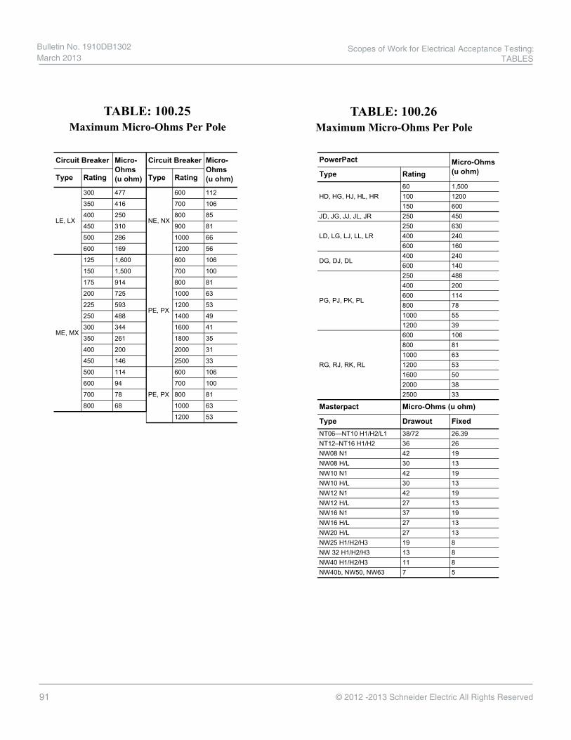
91 © 2012 -2013 Schneider Electric All Rights Reserved
Maximum Micro-Ohms Per PoleTABLE: 100.25
Maximum Micro-Ohms Per PoleTABLE: 100.26
EN
GLIS
H
Field Testing and Maintenance Guide 0600IB1201Section 5—Electronic Trip Circuit Breaker Performance Tests (Except Masterpact™ and PowerPact™ Circuit Breakers) 03/2012
©2012SchneiderElectricAllRightsReserved42
Whensecondaryinjectiontestingusing the UTS3testset,thecircuitbreakermustbedisconnected fromthe Powerlogicsystem.To disconnectthe circuit breaker from the Powerlogicsystem,detach the4-pinplugconnection onthe adapter.Thetestsetwill indicatethecircuitbreakerfailedifthePowerlogicsystemremainsconnectedwhen testing. After testing,reconnectthe 4-pinplugto the adapter.FollowtheinstructionsfortheversionofPowerlogicsoftwarethatisinstalledonthesystemtoverifythatthecommunicationhasbeenre-established with the circuit breaker.
NOTE: Testingacircuitbreaker connectedtoaPowerlogicsystemcausesthe Powerlogic system to react as if thecircuitbreakerwereexperiencingtheactual faults.
Contact Resistance Test
Circuitbreakerpoleresistancetestsarenotreliableindicatorsofcircuitbreaker performance because the resistancevaluesareinfluencedbyanumberoftransientfactorsincludingcontactsurfaceoxidation,foreignmaterial between thecontacts,andtesting methods.NEMAAB4 paragraph6.4.1states:“The millivoltdrop of acircuitbreaker polecanvarysignificantlydue toinherentvariability intheextremelowresistanceoftheelectricalcontactsandconnectors.Suchvariations do notnecessarilypredictunacceptable performanceandshallnotbe usedasthesole criteriafordetermination ofacceptability.”
Highpole resistancemayalsobe caused by erodedcontacts,lowcontactforce,andloosetermination. Theonlyone ofthesefactorslikelytobe presentonanewcircuitbreakerisa loosetermination,sincethecontactsarenewand there has been no opportunity for contactpressureto havedriftedfromthefactorysetting.Aloose termination can be corrected in the field.
Ifacontactresistancetestisdone,itisimportanttodo it afterthecontactshavebeen conditionedbyinstantaneousprimaryinjection testingtoensurethecontactsareclearof resistivefilms, oxidationand foreignmaterial.Ifthecircuitbreakerhasbeen in servicewithno performanceissues,(overheating or nuisance tripping),contactresistancemeasurementsareredundantandoflittle value.
SquareDrecommendsthataDLRO(DigitalLowResistanceOhmmeter)beused,usinga10Adctestcurrentforcircuitbreakerratingsbelow100A,andusing 100Adc forcircuitbreakersrated100 Aand above.themedian(middle)value of threereadings (toggling thecircuitbreakerbetweeneachreading) shouldberecorded foreachpoletested.Ifthis valueisequaltoorlessthanthe valuelisted in Table10,the poleis acceptable.Ifthe reading ishigher,thecauseshouldbeinvestigatedandcorrectedif possible.Contactyour localfieldofficeformoreinformation.
Remove Test Connections Uponcompleting testing:
— Removetestconnectionsfromcircuitbreaker.— Inspectconnectionsfordamagecausedbytesting.— Resetthelong-timepickup switchto original settings, as recorded in
above.— If an auxiliary power supply is being used for the Micrologic trip unit,
reconnecttheauxiliarypowersupply.
Additional Information Formore informationconcerning SquareDCircuitbreakers,refertotheappropriateinstructionmanual.Thesemanualscontain installationinstructions,mounting information,safety features, wiring diagrams, andtroubleshooting charts for specific circuit breakers.
Table 10: Maximum Micro-Ohms Per Pole
Circuit Breaker Micro-Ohms(u ohm)
Circuit Breaker Micro-Ohms(u ohm)Type Rating Type Rating
LE,LX
300 477
NE,NX
600 112
350 416 700 106
400 250 800 85
450 310 900 81
500 286 1000 66
600 169 1200 56
ME,MX
125 1,600
PE,PX
600 106
150 1,500 700 100
175 914 800 81
200 725 1000 63
225 593 1200 53
250 488 1400 49
300 344 1600 41
350 261 1800 35
400 200 2000 31
450 146 2500 33
500 114
PE,PX
600 106
600 94 700 100
700 78 800 81
800 68 1000 63
1200 53
ENG
LISH
Field Testing and Maintenance Guide 0600IB1201Section 4—Masterpact™ and PowerPact™ Circuit Breaker Performance Tests 03/2012
©2012SchneiderElectricAllRightsReserved32
Contact Resistance Test
Circuitbreakerpoleresistancetestsarenotreliableindicatorsofcircuitbreakerperformancebecausetheresistancevaluesareinfluencedbyanumberoftransientfactorsincludingcontactsurfaceoxidation,foreignmaterial between thecontacts,andtesting methods.NEMAAB4 paragraph6.4.1states:“The millivoltdrop of acircuitbreaker polecanvarysignificantlydue toinherentvariability intheextremelowresistanceoftheelectricalcontactsandconnectors.Suchvariations do notnecessarilypredictunacceptable performanceandshallnotbe usedasthesole criteriafordetermination ofacceptability.”
Highpoleresistancemayalsobecaused byeroded contacts,lowcontactforce,andloosetermination.Theonly one of thesefactorslikely to bepresenton anewcircuitbreaker isaloosetermination,sincethecontactsare newandtherehasbeenno opportunityforcontactpressure tohavedriftedfromthe factorysetting. Aloosetermination canbecorrectedin thefield.
Ifacontactresistancetestisdone,itisimportanttodo it afterthecontactshavebeen conditionedbyinstantaneousprimaryinjection testingtoensurethecontactsareclearof resistivefilms, oxidationand foreignmaterial.Ifthecircuitbreakerhasbeen in servicewithno performanceissues,(overheating or nuisance tripping),contactresistancemeasurementsareredundantandoflittle value.
SquareDrecommendsthataDLRO(DigitalLowResistanceOhmmeter)beused,usinga10Adctestcurrentforcircuitbreakerratingsbelow100A,andusing 100Adc forcircuitbreakersrated100 Aand above.themedian(middle)value of threereadings (toggling thecircuitbreakerbetweeneachreading) shouldberecorded foreachpoletested.Ifthis valueisequaltoorless than the value listed in Table 8, thepoleisacceptable.Ifthereadingishigher,thecauseshouldbeinvestigatedandcorrectedif possible.Contactyour localfieldofficeformoreinformation.
Table 8: Maximum Micro-Ohms Per Pole
PowerPact Micro-Ohms(u ohm)Type Rating
HD,HG,HJ,HL,HR60 1,500100 1200150 600
JD,JG,JJ,JL,JR 250 450
LD,LG,LJ,LL,LR250 630400 240600 160
DG,DJ,DL400 240600 140
PG,PJ,PK,PL
250 488400 200600 114800 781000 551200 39
RG,RJ,RK,RL
600 106800 811000 631200 531600 502000 382500 33
Masterpact Micro-Ohms (u ohm)
Type Drawout FixedNT06—NT10H1/H2/L1 38/72 26.39NT12–NT16H1/H2 36 26NW08N1 42 19NW08H/L 30 13NW10N1 42 19NW10H/L 30 13NW12N1 42 19NW12H/L 27 13NW16N1 37 19NW16H/L 27 13NW20H/L 27 13NW25H1/H2/H3 19 8NW32H1/H2/H3 13 8NW40H1/H2/H3 11 8NW40b,NW50,NW63 7 5
Scopes of Work for Electrical Acceptance Testing: TABLES
Bulletin No. 1910DB1302 March 2013

92© 2012 -2013 Schneider Electric All Rights Reserved
Bkr. Frame Size Micro-ohmsDS206 200
DSL206 200
DS206S 200
DS416 65
DSL416 70
DS416S 65
DS420 65
DS632 40
DS840 40
Contact Resistance Maximum Contact Resistance
Type DS, DSII, DSL, and DSLII Circuit Breaker
TABLE: 100.27
Bulletin No. 1910DB1302 March 2013
Scopes of Work for Electrical Acceptance Testing: TABLES

93 © 2012 -2013 Schneider Electric All Rights Reserved
Comments or Suggestions?
Schneider Electric Services has developed these procedures using the most updated techniques and references available at the time of publication, however, we are continually updating and revising our processes to reflect changing industry requirements and best practices. If you observe any errors or omissions in this document, or simply have a suggestion for improvement, we would like to hear from you.
Please complete the information below and mail or e-mail it to the indicated address.
Name: ________________________________________________________Company: _____________________________________________________Address: ______________________________________________________City / State / Zip: ________________________________________________E-mail:________________________________________________________Phone:________________________________________________________
Do you wish to be contacted regarding your comment: Yes No
Please return to:Services Installed Base Solutions 1010 Airpark CenterNashville, TN 37217
Email: [email protected] subject tile: ATP Bulletin - Comments/Suggestions
Reference Page Number and/or Paragraph: __________________________
Comment/Suggestion Notes: ________________________________________________________________________________________________________________________________________________________________________________________________________________________________________________________________________________________________________________________________________________________________________________________________________________________________________________________________________________________________________________________________________________________________________________
Ommission Suggestion Other Comment Error
Scopes of Work for Electrical Acceptance Testing: COMMENTS/SUGGESTIONS
Bulletin No. 1910DB1302 March 2013

Our culture of safety helps mitigate your risks• OurNorthAmerican
OperatingDivisionisoneofanelitegroupofcompaniestosimultaneouslyholdtheRobertW.CampbellAward(2009)andtheGreenCrossAward(2011).
• TheNationalSafetyCouncilhasrecognizedSchneiderElectricwithover50“OperationalExcellence”safetyawardsineachofthepastthreeyears.
Services SummaryAspartofSchneiderElectric,theglobalspecialistinenergymanagement,SchneiderElectricFieldServicesisaqualified,fullserviceorganizationdedicatedtohelpingmanagethelifecycleofelectricaldistributionequipment,nomatterwhatbranditis.
Ourelectricaldistributionservicesteamiscomprisedofover300FieldServiceRepresentativeswhoarequalifiedasdefinedbyNFPA70E®andOSHA.Thesefullyqualifiedrepresentatives,supportedbyover150designandapplicationprofessionalengineers,provideanationwidenetworkoftrainedprofessionalsthatareoncall24/7toensurethatyourelectricaldistributionequipmentfunctionsproperly.
Schneider Electric USA, Inc.1415 S. Roselle Road
Palatine, IL 60067
Tel: 847-397-2600
Fax: 847-925-7500
www.schnedier-electric.com
Document Number: 1910DB1302
©-2
013
Sch
neid
er E
lect
ric
All
Rig
hts
Res
erve
d. S
chne
ider
Ele
ctri
c, M
ake
the
mo
st o
f yo
ur e
nerg
y, a
nd F
useL
og
ic a
re
trad
emar
ks o
wne
d b
y S
chne
ider
Ele
ctri
c In
dus
trie
s S
AS
. A
ll o
ther
tra
dem
arks
are
the
pro
per
ty o
f th
eir
resp
ectiv
e o
wne
rs.
March 2013