supplemental hazard analysis and risk assessment ...€¦ · supplemental hazard analysis and risk...
TRANSCRIPT
Supplemental Hazard Analysis and Risk Assessment – Hydrotreater
Peter P. Lowry Katie A. Wagner
April 2015
PNNL-24275

DISCLAIMER This report was prepared as an account of work sponsored by an agency of the United States Government. Neither the United States Government nor any agency thereof, nor Battelle Memorial Institute, nor any of their employees, makes any warranty, express or implied, or assumes any legal liability or responsibility for the accuracy, completeness, or usefulness of any information, apparatus, product, or process disclosed, or represents that its use would not infringe privately owned rights. Reference herein to any specific commercial product, process, or service by trade name, trademark, manufacturer, or otherwise does not necessarily constitute or imply its endorsement, recommendation, or favoring by the United States Government or any agency thereof, or Battelle Memorial Institute. The views and opinions of authors expressed herein do not necessarily state or reflect those of the United States Government or any agency thereof. PACIFIC NORTHWEST NATIONAL LABORATORY operated by BATTELLE for the UNITED STATES DEPARTMENT OF ENERGY under Contract DE-AC05-76RL01830 Printed in the United States of America Available to DOE and DOE contractors from the Office of Scientific and Technical Information,
P.O. Box 62, Oak Ridge, TN 37831-0062; ph: (865) 576-8401 fax: (865) 576-5728
email: [email protected] Available to the public from the National Technical Information Service, U.S. Department of Commerce, 5285 Port Royal Rd., Springfield, VA 22161
ph: (800) 553-6847 fax: (703) 605-6900
email: [email protected] online ordering: http://www.ntis.gov/ordering.htm
This document was printed on recycled paper.
(9/2003)


Supplemental Hazard Analysis and Risk Assessment – Hydrotreater
This page intentionally left blank
i

Supplemental Hazard Analysis and Risk Assessment – Hydrotreater
Executive Summary
A supplemental hazard analysis was conducted and quantitative risk assessment performed in response to an independent review comment received by the Pacific Northwest National Laboratory (PNNL) from the U.S. Department of Energy Pacific Northwest Field Office (PNSO) against the Hydrotreater/Distillation Column Hazard Analysis Report issued in April 2013. The comment states:
“…based on our independent review and in light of our code responsibilities as the owner, we are directing Battelle to provide PNSO with the following items prior to start-up of the distillation column:
…
“3. Identification of prudent protective actions for the worker and the public (e.g., set-back distances, shielding, procedures for minimizing time in the higher risk areas during operation, etc.) based on quantitative analysis and practical risk minimization approaches (for the distillation column).
Items 1 and 3 are also expected to be provided to PNSO for the hydrotreater unit prior to its operation…” (Emphasis added)
The supplemental analysis used the hazardous conditions documented by the previous April 2013 report as a basis. The conditions were screened and grouped for the purpose of identifying whether additional prudent, practical hazard controls could be identified, using a quantitative risk evaluation to assess the adequacy of the controls and establish a lower level of concern for the likelihood of potential serious accidents. Calculations were performed to support conclusions where necessary.
Additional controls were identified where the quantitative analysis demonstrated a need for additional preventive or mitigative measures. These include:
1. Modification of the safe operating procedure (SOP) to state that 1) any leak testing of the system (with nitrogen) will be conducted with the ventilation system operational and 2) the nitrogen system will be closed when not in use. This mitigates the presence of an oxygen deficient atmosphere during maintenance activities and non-operational timeframes. [Action Completed as part of Distillation Column Supplemental Hazard Analysis and Risk Assessment].
2. Modification of the SOP to require the operator to minimize the stay time within the enclosure during hydrotreater operations. This decreases the time an operator is subject to any incidents that might occur within the enclosure. [Action Completed as part of Distillation Column Supplemental Hazard Analysis and Risk Assessment].
3. Administrative controls to check relief header - Modify the SOP to require verification that the low pressure relief line is free of obstruction (e.g., mud dauber nest) (U-7 bounding event).
The following additional follow-on action items were identified during the analysis to verify assumptions or enhance worker safety:
1. During startup testing, ensure that valves fail in the appropriate direction, based on their credited function, on loss of air.
ii

Supplemental Hazard Analysis and Risk Assessment – Hydrotreater
2. Review areas of operator proximity to high pressure/high temperature system
components to ensure adequate personal protective equipment (PPE) is provided against flashing steam release.
These additional hazard controls are prudent, practical measures to reduce risk to workers and the public. They will be implemented prior to operation of the hydrotreater unit.
iii
Supplemental Hazard Analysis and Risk Assessment – Hydrotreater
Contents Executive Summary ........................................................................................................... ii Introduction and Purpose .................................................................................................. 1 Scope and Methodology ................................................................................................... 1 Results .............................................................................................................................. 4 Conclusion ........................................................................................................................ 5 References ....................................................................................................................... 6 Table 1. Frequency Values and Data Sources ................................................................. 8 Table 2. Supplemental Hazard Analysis and Risk Assessment Evaluation –
Hydrotreater ............................................................................................................ 18 Appendix A: Valve Calculation ....................................................................................... 36 Appendix B. Chemical Safety Data Sheets .................................................................... 37
iv

Supplemental Hazard Analysis and Risk Assessment – Hydrotreater
Introduction and Purpose
This report documents a supplemental analysis to the Hydrotreater/Distillation Column Hazard Analysis Report issued in April 2013. The supplemental analysis session was held March 9th-11th, 2015, in response to an independent review comment transmitted to the Pacific Northwest National Laboratory (PNNL) via letter from the U.S. Department of Energy Pacific Northwest Field Office (PNSO; 14-PNSO-0215). The comment states:
“…based on our independent review and in light of our code responsibilities as the owner, we are directing Battelle to provide PNSO with the following items prior to start-up of the distillation column:
…
“3. Identification of prudent protective actions for the worker and the public (e.g., set-back distances, shielding, procedures for minimizing time in the higher risk areas during operation, etc.) based on quantitative analysis and practical risk minimization approaches (for the distillation column).
Items 1 and 3 are also expected to be provided to PNSO for the hydrotreater unit prior to its operation…” (Emphasis added)
The purpose of the review was two-fold: identify prudent, practical protective actions for workers and the public, and use a quantitative analysis as the basis for this selection.
Scope and Methodology
The baseline analysis upon which this supplemental analysis builds is the Hydrotreater/Distillation Column Hazard Analysis Report (PNNL, 2013) and uses the hazardous conditions cited therein (Table 3-4 of PNNL, 2013) as the basis for evaluation. The hazardous conditions considered were then screened and grouped as follows:
- Items retained included process safety-related hazards that fall outside of the normal operating envelope of PNNL. Standard laboratory hazards, such as trips, slips, falls, work with compressed gases, etc., are within the PNNL normal operating envelope for which safety programs have been implemented and require no further analysis.
- Items retained included those related to operation of the hydrotreater or to utility systems that affect or could be affected by hydrotreater operation. [Items related to operation of the distillation column were evaluated during a supplementary hazard analysis session conducted in June 2014 (PNNL, 2014).] Items related to utility systems that were evaluated in the distillation column report, and for which the hazardous event did not significantly change for hydrotreater operation, were not revisited (i.e., U-30 and U-33).
- Retained items were grouped so that bounding, representative conditions are evaluated. This includes the consideration of initiators, hazard controls, and consequence types.
1

Supplemental Hazard Analysis and Risk Assessment – Hydrotreater
This screening and grouping approach provided a subset of hazardous conditions to be analyzed, while assuring that any additional hazard controls selected are broadly applicable to the hazards associated with hydrotreater operations.
The methodology used follows a quantitative approach. The frequency of the initiating event, together with the likelihood that hazard controls (including critical controls) will not function as designed is quantitatively estimated. Failure of all controls is required for the hazardous condition (consequence) to occur. These likelihoods are binned by frequency ranges. The consequences of the hazardous conditions evaluated are also estimated, and binned by severity. Together, the frequency and consequence can be represented for each group of analyzed events in a risk matrix (Figure 1), based on Guidelines for Hazard Evaluation Procedures, 3rd edition (AIChE, 2008).
The risk matrix reflects criteria for risk acceptance that have been adopted for the project and used for the Supplemental Hazard Analysis and Risk Assessment – Distillation Column (PNNL, 2014). A general criterion for a lower level of concern for the most serious accidents may be adopted from various sources. From the U.S. Department of Energy, EH-33 (DOE, 1996), the threshold for significant risk as adopted by the Occupational Safety and Health Administration (OSHA) in its final benzene rule is 10-3 fatality/year; the average annual accidental fatality risk in U.S. industries is 10-4 fatality/year. For the public, 10-4 fatality/year is often used as a maximum tolerable individual risk criterion (Lewis1, Travis2).
For this evaluation, PNNL has established a lower frequency value of 10-5 hazardous conditions/year for determining risk, which includes the potential for serious accidents affecting workers or the public. This frequency corresponds to the generic catastrophic failure rate for pressure vessels, including those routinely encountered by the public, posing pressure hazards and containing hazardous and flammable materials (Lees, 2012). Should the frequency of a specific hazardous condition fall to a small fraction of the likelihood of a catastrophic pressure vessel failure (10-5/year), the risk is considered small enough that additional controls are unnecessary.
When additional controls needed to lower the likelihood of a hazardous condition were considered neither practical nor prudent, actions to reduce consequences were identified instead. This approach follows a control hierarchy consistent with established DOE guidance (DOE, 2006) that emphasizes preventive over mitigative controls, and engineered controls over administrative controls.
For events that do not result in an energetic release from a pressure vessel failure, consequences are less severe and a higher likelihood of occurrence may be justified, based on risk (see Figure 1).
1 Lewis, Steven. “Risk Criteria – When is low enough good enough?” American Society of Safety Engineers- Middle East Chapter. 8th Professional Development Conference & Exhibition (PDC&E), February 2008. 2 Travis, C.C., et al., “Cancer risk management: A review of 132 federal regulatory decisions,” Environ. Sci. Technol., Vol. 21. No. 5. 1987.
2
Supplemental Hazard Analysis and Risk Assessment – Hydrotreater
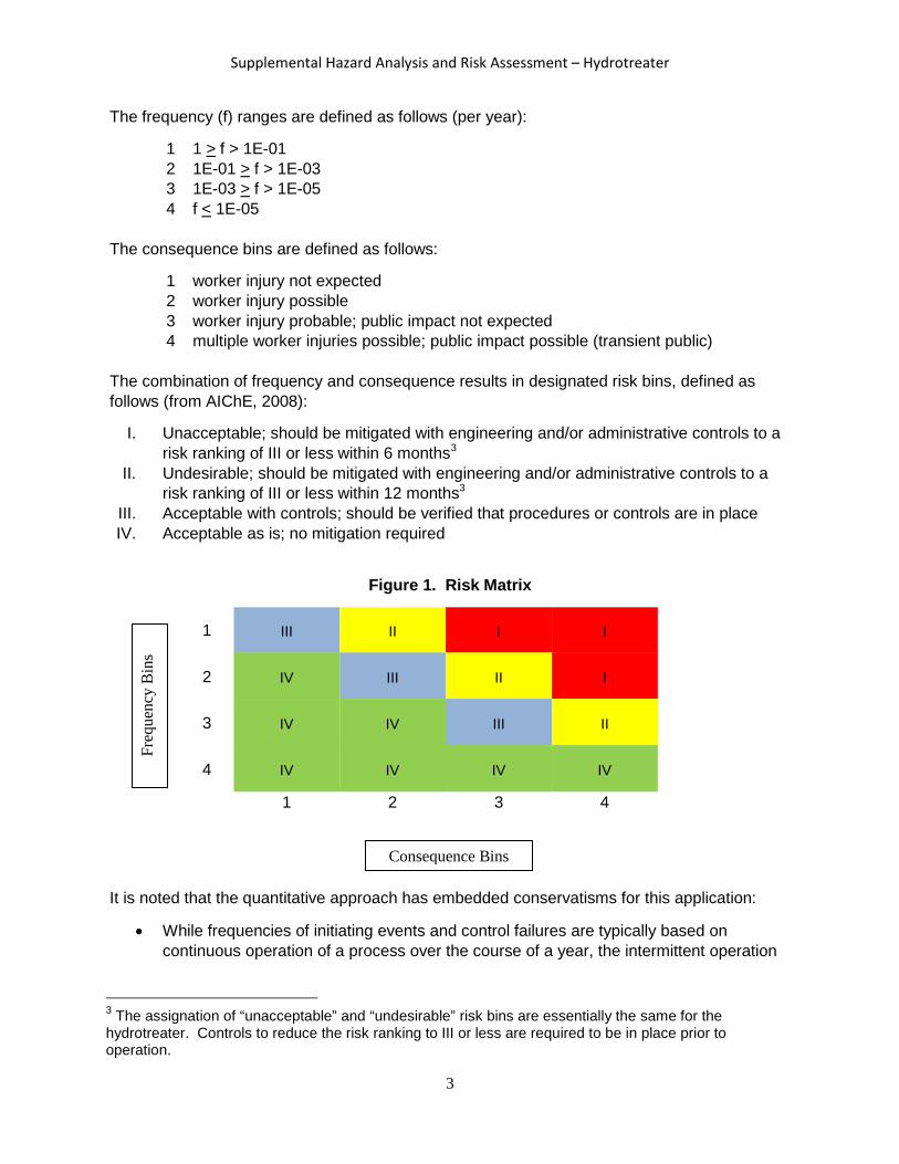
The frequency (f) ranges are defined as follows (per year):
1 1 > f > 1E-01 2 1E-01 > f > 1E-03 3 1E-03 > f > 1E-05 4 f < 1E-05
The consequence bins are defined as follows:
1 worker injury not expected 2 worker injury possible 3 worker injury probable; public impact not expected 4 multiple worker injuries possible; public impact possible (transient public)
The combination of frequency and consequence results in designated risk bins, defined as follows (from AIChE, 2008):
I. Unacceptable; should be mitigated with engineering and/or administrative controls to a risk ranking of III or less within 6 months3
II. Undesirable; should be mitigated with engineering and/or administrative controls to a risk ranking of III or less within 12 months3
III. Acceptable with controls; should be verified that procedures or controls are in place IV. Acceptable as is; no mitigation required
Figure 1. Risk Matrix
1 III II I I
2 IV III II I
3 IV IV III II
4 IV IV IV IV
1 2 3 4
It is noted that the quantitative approach has embedded conservatisms for this application:
• While frequencies of initiating events and control failures are typically based on continuous operation of a process over the course of a year, the intermittent operation
3 The assignation of “unacceptable” and “undesirable” risk bins are essentially the same for the hydrotreater. Controls to reduce the risk ranking to III or less are required to be in place prior to operation.
Freq
uenc
y B
ins
Consequence Bins
3

Supplemental Hazard Analysis and Risk Assessment – Hydrotreater
of the hydrotreater is expected to occur over a small fraction of a full year, thereby reducing risk up to an order of magnitude from that reported.
• Each hazardous condition evaluated does not necessarily include all hazard controls that are in place. Because the events selected are representative, only those with a common set of controls are considered in the analysis.
Results
The supplemental analysis demonstrates that the hazardous conditions evaluated generally fall into Risk Bin IV with hazard controls in place. Table 2 summarizes the results of the supplemental analysis. The event severities were estimated from the available energy that may be released and environmental conditions postulated to exist for each scenario. The basis for frequency estimates are provided in Table 14. Frequencies of failures for which little or no relevant data exists are based on reasonably conservative engineering judgment or follow an accepted convention. For example, the frequency of an administrative control failure is generally considered to be an “anticipated event” (DOE, 2007) and is therefore estimated as 1E-01/year in this analysis.
The following additional hazard controls were identified during the analysis as prudent, practical measures to enhance worker safety:
1. Modification of the safe operating procedure (SOP) to state that 1) any leak testing of the system (with nitrogen) will be conducted with the ventilation system operational and 2) the nitrogen system will be closed when not in use. This mitigates the presence of an oxygen deficient atmosphere during maintenance activities and non-operational timeframes. [Action Completed as part of Distillation Column Supplemental Hazard Analysis and Risk Assessment].
2. Modification of the SOP to require the operator to minimize the stay time within the enclosure during hydrotreater operations. This decreases the time an operator is subject to any incidents that might occur within the enclosure. [Action Completed as part of Distillation Column Supplemental Hazard Analysis and Risk Assessment].
3. Administrative controls to check relief header - Modify the SOP to require verification that the low pressure relief line is free of obstruction (e.g., mud dauber nest) (U-7 bounding event).
Two hazardous events, included and noted in Table 2, were prevented due to either the design of gas fittings or to a hydrotreater design change. Specifically, 1) the introduction of oxygen and hydrogen at the same time (H.1-17) was prevented due to compressed oxygen and air having a different fitting connection than compressed nitrogen and 2) an operator inadvertently releasing contents of reactor into the enclosure was prevented with the addition of a 3-way valve (H.6-1).
In addition, questions were raised during the session, regarding critical characteristics of high/low pressure interface valves (H.1-11, H.1-21, H.4-23 and H.4-24) associated with
4 Note that some initiating event frequencies have been adjusted since the April 2013 hazard analysis, based on re-evaluation of the hazardous condition or on the addition of engineered features to the design or administrative controls to procedures.
4

Supplemental Hazard Analysis and Risk Assessment – Hydrotreater
hazardous events, which were addressed with the aid of additional calculations (Appendix A). Calculations demonstrate that the valves have been appropriately sized for potential flow rates associated with hazardous events and identified controls are sufficient.
For several hazardous events involving leaks of bio-oil, sulfiding agents, and water byproduct, the consequence likelihood would be further reduced from reported levels with the application of required personal protective equipment (Appendix B. Chemical Safety Data Sheets).
Based on the supplemental hazard analysis and the application of the existing and additional hazard controls, the frequencies and mitigated consequences of the potential hazardous conditions were generally considered to fall into Risk Bin IV.
The following additional follow-on action items were identified during the analysis to verify assumptions or enhance worker safety:
1. During startup testing, ensure that valves fail in the appropriate direction, based on their credited function, on loss of air.
2. Review areas of operator proximity to high pressure/high temperature system components for use of personal protective equipment (PPE) against flashing steam release events.
Conclusion
This supplementary analysis and the quantitative risk evaluation performed has demonstrated that an adequate set of hazard controls are in place to address the potential hazardous conditions associated with hydrotreater operation. Frequencies of initiating events and enabling process control failures were established and considered in evaluating the adequacy of the controls in place.
Additional controls were identified where the quantitative analysis or qualitative considerations (e.g., defense in depth) demonstrated a need for additional preventative or mitigative measures. These include: 1) requiring leak testing of the system (with nitrogen) to be conducted with the ventilation system operational and closing the nitrogen system when not in use, 2) limiting stay time for operators within the enclosure, and 3) requiring the verification of an open flow path (with nitrogen) to the relief header prior to each run. These additional controls are considered practical and prudent for further reducing risk to workers and the public, and will be established prior to operation of the hydrotreater unit. In addition, there were follow-on action items identified to verify assumptions or enhance worker safety, including, 1) ensure valves fail in the appropriate direction upon loss of air and 2) evaluate use of PPE for protection against steam release events.
5

Supplemental Hazard Analysis and Risk Assessment – Hydrotreater
References
AIChE, 2008. Guidelines for Hazard Evaluation Procedures, 3rd edition. Center for Chemical Process Safety, New York, New York.
DOE, 2007. DOE-STD-5506-2007, Preparation of Safety Basis Documents for Transuranic (TRU) Waste Facilities. U.S. Department of Energy, Washington, D.C.
DOE, 2006. DOE-STD-3009-94, Change Notice 3, Preparation Guide for U.S. Department of Energy Nonreactor Nuclear Facility Documented Safety Analyses. U.S. Department of Energy, Washington, D.C.
DOE, 1996. Hazard and Barrier Analysis Guidance Document, EH-33 Office of Operating Experience Analysis and Feedback, U.S. Department of Energy, Washington, D.C.
Lees, 2012. Loss Prevention in the Process Industries, 4th Edition. Elsevier, Inc., Oxford, UK.
PNNL, 2013. Hydrotreater/Distillation Column Hazard Analysis Report, April 2013. Pacific Northwest National Laboratory, Richland, Washington.
PNNL, 2014. Supplemental Hazard Analysis and Risk Assessment – Distillation Column, July 2014. Pacific Northwest National Laboratory, Richland, Washington.
6

Supplemental Hazard Analysis and Risk Assessment – Hydrotreater
This page intentionally left blank
7

Supplemental Hazard Analysis and Risk Assessment – Hydrotreater
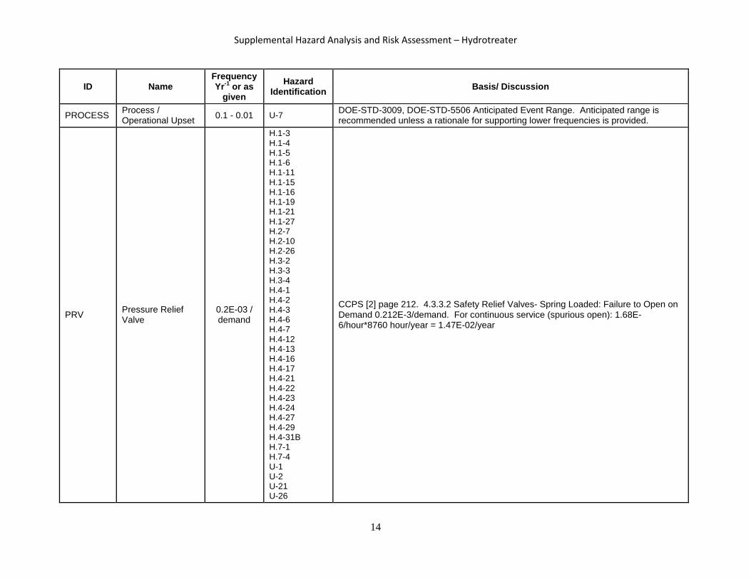
Table 1. Frequency Values and Data Sources
ID Name Frequency Yr-1 or as
given Hazard
Identification Basis/ Discussion
CV Check Valve 0.0438 H.4-1 Smith 1985 [8] reports 5.00E-06/hr
EFV Excess Flow Valve 1.30E-02/demand
H.4-10 U-10 U-24 U-25 U-31
http://www.hse.gov.uk/landuseplanning/failure-rates.pdf
FD Flame Detection 0.117 - 0.0117
H.4-10 H.4-11 U-9 U-10 U-25
Lees [1] Table A14.56 Used Ultra-violet Detector fail to operate 108E-03 /year 2 Detectors, Used Common Cause factor 10X (Assumed Environment in Enclosure is bounded based on data.)
FS Fire Suppression 0.0425/d
H.4-10 H.4-11 U-9 U-10 U-25
CCPS [2] page 208 4.2.4.1 Mist system- used fire pumps 4.25E-1/demand
Assumed sprinklers not actuated/did not function – prob. 0.1. [3] (Note: Assumed fire large enough to cause a BLEVE concern would actuate sprinklers.)
GD Flam Gas/vapor detection
0.053 - 0.0053
H.4-10 H.4-11 H.4-26 H.4-28 H.8-2 H.8-3 U-9 U-10 U-25 U-32
CCPS [2] page 33 Gas detectors =(44/1.6E7) * 8760 = 0.0231/year
2 Detectors. Used 10X for environs (potential high heat) and 10X common cause.
8

Supplemental Hazard Analysis and Risk Assessment – Hydrotreater
ID Name Frequency Yr-1 or as
given Hazard
Identification Basis/ Discussion
IGN1(EN) Ignition of spill - product
0.01 - 0.001
H.1-8 H.1-12 H.1-14 H.2-9 H.2-17 H.4-11 H.5-2 H.7-5 H.7-9 U-3 U-4 U-5 U-6 U-9 U-32
Engineering Assumption: Ignition Range based on spray of “finished product” (0.01) versus spill (0.001). Assume ignition is 0.1 /event if outside of Class 1 Div 2 Environment.
IGN2(EN) Ignition of Hydrogen (leak) Vapors
5.00E-01
H.2-1 H.2-2 H.2-3 H.2-15 H.4-8 H.4-10 H.4-15 H.4-19 H.4-20 H.4-23 H.4-24 H.4-26 H.4-28 H.7-7 H.7-8 H.8-2 H.8-3 U-10 U-24 U-25 U-31
Engineering Assumption: 0.5 for "autoignition" of hydrogen in Class 1 Div. 2 Environment.
IGN3 Ignition in vessel 1.00E-03 U-8 Engineering Assumption: Ignition source in vessel. Assumed to be equal to lower range of IGN1.
9
Supplemental Hazard Analysis and Risk Assessment – Hydrotreater
ID Name Frequency Yr-1 or as
given Hazard
Identification Basis/ Discussion
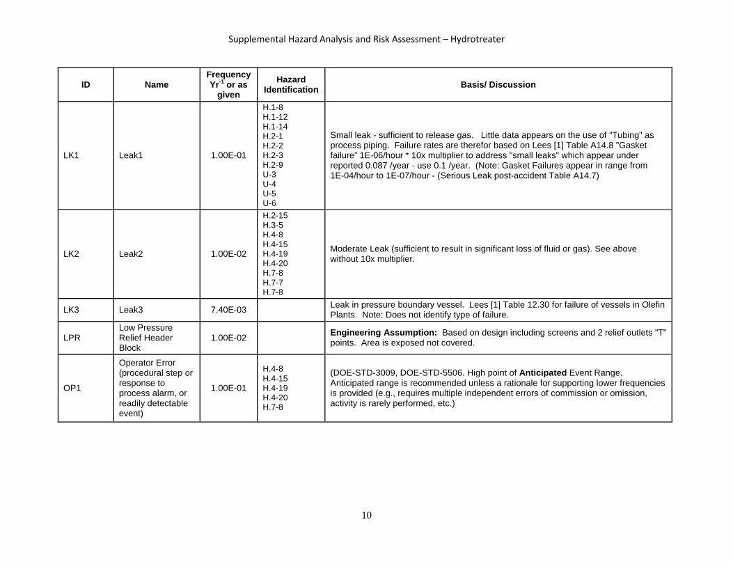
LK1 Leak1 1.00E-01
H.1-8 H.1-12 H.1-14 H.2-1 H.2-2 H.2-3 H.2-9 U-3 U-4 U-5 U-6
Small leak - sufficient to release gas. Little data appears on the use of "Tubing" as process piping. Failure rates are therefor based on Lees [1] Table A14.8 "Gasket failure” 1E-06/hour * 10x multiplier to address "small leaks" which appear under reported 0.087 /year - use 0.1 /year. (Note: Gasket Failures appear in range from 1E-04/hour to 1E-07/hour - (Serious Leak post-accident Table A14.7)
LK2 Leak2 1.00E-02
H.2-15 H.3-5 H.4-8 H.4-15 H.4-19 H.4-20 H.7-8 H.7-7 H.7-8
Moderate Leak (sufficient to result in significant loss of fluid or gas). See above without 10x multiplier.
LK3 Leak3 7.40E-03 Leak in pressure boundary vessel. Lees [1] Table 12.30 for failure of vessels in Olefin Plants. Note: Does not identify type of failure.
LPR Low Pressure Relief Header Block
1.00E-02 Engineering Assumption: Based on design including screens and 2 relief outlets "T" points. Area is exposed not covered.
OP1
Operator Error (procedural step or response to process alarm, or readily detectable event)
1.00E-01
H.4-8 H.4-15 H.4-19 H.4-20 H.7-8
(DOE-STD-3009, DOE-STD-5506. High point of Anticipated Event Range. Anticipated range is recommended unless a rationale for supporting lower frequencies is provided (e.g., requires multiple independent errors of commission or omission, activity is rarely performed, etc.)
10

Supplemental Hazard Analysis and Risk Assessment – Hydrotreater
ID Name Frequency Yr-1 or as
given Hazard
Identification Basis/ Discussion
OP2
Operator Error (enhanced procedure – Safety alarm)
5.00E-02
H.1-7 H.1-10 H.1-13 H.1-18 H.1-20 H.1-22 H.1-23 H.1-24 H.1-25 H.1-28 H.2-8 H.2-16 H.2-22 H.2-23 H.2-24 H.2-25 H.3-6 H.4-12 H.4-13 H.4-16 H.4-21 H.4-31a H.4-32 H.4-33 H.5-3 H.8-1 U-7 U-15 U-26 U-29
EH-33[4] 5X Nominal value for failure to respond to Compelling Signal given many competing signals.
OP3
Operator Error failure to detect and respond to off-normal system
5.00E-01
H.4-10 H.4-11 U-9 U-10 U-25
CCPS [5] Table 3.17 failure to perform required action (based on contact with control room) used when event includes a time urgent/higher stress response and for non-procedure driven operator response actions.
P1 Single Process Instrument/Alarm 3.00E-01 H.4-4
H.4-5
EH-33[4] Table A.1 General Instrumentation (sum of fail to operate and shift calibration. 3.1E-5/hour) Lees [1] Table A14.53. Bounds average of all reported mean failure rates. [(26 +33+18+56)/4 ]/106 hour
11

Supplemental Hazard Analysis and Risk Assessment – Hydrotreater
ID Name Frequency Yr-1 or as
given Hazard
Identification Basis/ Discussion
P2 2 Process Instruments/ Alarms
6.00E-02
H.1-1 H.1-2 H.1-3 H.1-4 H.1-5 H.1-6 H.1-19 H.1-27 H.2-15 H.2-20 H.3-2 H.3-3 H.3-4 H.3-6 H.4-2 H.4-3 H.4-6 H.4-7 H.4-17 H.4-27 H.7-1 H.7-7 U-1 U-2 U-21
CCPS [5] PP 363 Beta Factor 0.2 (Range 0.1-0.2) For a 2 component system = (CCF* Failure Rate) = 0.2*P1.
12

Supplemental Hazard Analysis and Risk Assessment – Hydrotreater
ID Name Frequency Yr-1 or as
given Hazard
Identification Basis/ Discussion
P3 Process Critical Control 1.00E-02
H.1-1 H.1-2 H.1-3 H.1-4 H.1-5 H.1-6 H.1-19 H.1-27 H.2-20 H.3-6 H.4-2 H.4-3 H.4-6 H.4-7 H.7-1 U-3 U-4 U-5 U-6 U-15
Engineering Assumption: Used Lower End of SIL-1 for Critical Control Instrumentation [6].
PC1 Catastrophic failure of pipe 2.93E-06 U-24
CCPS [2] page 183. 3.2.1.1 Piping systems – Metal – Straight sections. Upper = 1.04E-01/106 mile-hours = 2.68E-02 / (8760 hours/year / 106 hours) = 9.11E-04/mile-year = 9.11E-04 * (17feet/5280feet/mile) = 2.93E-06. For hydrotreater, the use of 2.93E-06 represents a catastrophic piping break. The frequency for small leaks was increased by 10E+01.
PCV Pressure Control Valve 0.0314
H.1-15 H.1-16 H.2-7 H.2-10 H.2-26 H.4-23 H.4-24 H.4-29 H.4-31B H.7-4
CCPS [2] page 201. 3.5.3.3 Pneumatic operated valves. Mean 3.59E-06/hour
PDL PDL maintain Concentration < limit
0.1 / demand U-24 Engineering Assumption: building size/ventilation unable to maintain gas to below
hazardous limits or LFL = 0.1/demand
13
Supplemental Hazard Analysis and Risk Assessment – Hydrotreater
ID Name Frequency Yr-1 or as
given Hazard
Identification Basis/ Discussion
PROCESS Process / Operational Upset 0.1 - 0.01 U-7 DOE-STD-3009, DOE-STD-5506 Anticipated Event Range. Anticipated range is
recommended unless a rationale for supporting lower frequencies is provided.
PRV Pressure Relief Valve
0.2E-03 / demand
H.1-3 H.1-4 H.1-5 H.1-6 H.1-11 H.1-15 H.1-16 H.1-19 H.1-21 H.1-27 H.2-7 H.2-10 H.2-26 H.3-2 H.3-3 H.3-4 H.4-1 H.4-2 H.4-3 H.4-6 H.4-7 H.4-12 H.4-13 H.4-16 H.4-17 H.4-21 H.4-22 H.4-23 H.4-24 H.4-27 H.4-29 H.4-31B H.7-1 H.7-4 U-1 U-2 U-21 U-26
CCPS [2] page 212. 4.3.3.2 Safety Relief Valves- Spring Loaded: Failure to Open on Demand 0.212E-3/demand. For continuous service (spurious open): 1.68E-6/hour*8760 hour/year = 1.47E-02/year
14

Supplemental Hazard Analysis and Risk Assessment – Hydrotreater
ID Name Frequency Yr-1 or as
given Hazard
Identification Basis/ Discussion
PSV Pressure Safety Valve
0.0415 / demand CCPS [2] page 211. 4.3.3.2 Safety Relief Valves- Pilot Operated PRV 4.15E-3 /d * 10
for liquid service conditions.
QD Quick Disconnect 0.0210 H.5-2 H.7-5 2.40E-06/hr
VC1 Catastrophic Failure of Vessel 1.00E-05
H.1-18 H.4-9 H.4-18
Lees [1] pp 609 establishes a mean failure rate of 1E-5 for disruptive failures of pressure vessel (Hurst, Davies et al, 1994). CCPS [2] 3.6.2.1 Metallic Pressurized Vessel establishes a range 3.85E-4 (upper), 9.55E-05 (mean) 1.24E-6 (lower) for "all failures". For Hydrotreater/Distillation Column vessels, the use of 1E-5 failure / year represents a conservative estimate based on the following considerations: 1) Use of 316 Stainless Steel (SS) as material of construction, SS provides excellent resistance to corrosion and a number of material degradations issues for the conditions experience in HT/DC operations; SS ductility provides additional protection against catastrophic failures associated with (PVB and BLEVEs); the high ultimate strength SS provides an additional factor of safety compared to carbon steels commonly used in pressure vessels and thus included the above aggregate values. 2) Large margin between design pressure and normal operating pressure; 3) Demonstrated protection systems and environment minimize challenges (temperature, pressure, environment) to the vessels 4) Numerous sources (e.g., EH-33 [4]. Pittiglio [7]) identify "high standard" vessels having a factor of 10 lower failure frequency - it is assumed high standard equates to ASME standard or equivalent with modern construction techniques (post-1990) when looking at "world-wide" population of pressure vessels.
15

Supplemental Hazard Analysis and Risk Assessment – Hydrotreater
ID Name Frequency Yr-1 or as
given Hazard
Identification Basis/ Discussion
VENT Ventilation 1.00E-03
H.1-7 H.1-8 H.1-10 H.1-12 H.1-14 H.1-20 H.2-1 H.2-2 H.2-3 H.2-9 H.2-24 H.2-25 H.4-4 H.4-5 H.4-8 H.4-15 H.4-19 H.4-20 H.4-26 H.4-28 H.4-33 H.5-3 H.7-8 H.8-1 H.8-2 H.8-3 U-29
Engineering Assumption: Assumed failure per demand (Leaks) for which the ventilation system is not capable of maintaining air concentration in acceptable range. Assumes system is operation when process is running.
[1] F. P. Lees, Loss Prevention in the Process Industries, 4th Edition, 2012. [2] CCPS, Guidelines for Process Equipment Reliability Data, 1989. [3] NFPA, "U.S. Experience with Sprinklers," John R. Hall, Jr. June 2013. [4] DOE EH-33, HAZARD AND BARRIER ANALYSIS GUIDANCE DOCUMENT, 1996. [5] CCPS, Guidelines for Chemical Process Quantitative Risk Analysis, 2nd Edition. [6] ANSI/ISA 84, Application of Safety Instrumented Systems for the Process Industries, 2004. [7] [8]
Pittiglio, P. et al. “Updated failure rates and risk management in process industries,” 68th Conference of the Italian Thermal Machines Engineering Association, ATI2013. Smith, D.J., Reliability and Maintainability in Perspective, 2nd and 3rd editions, Macmillan London, 1985.
16

Supplemental Hazard Analysis and Risk Assessment – Hydrotreater
This page intentionally left blank
17
Supplemental Hazard Analysis and Risk Assessment – Hydrotreater
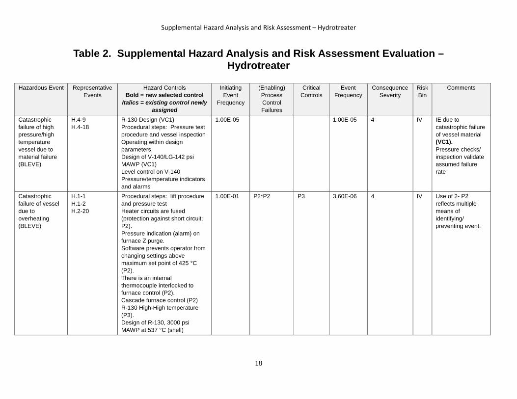
Table 2. Supplemental Hazard Analysis and Risk Assessment Evaluation –
Hydrotreater
Hazardous Event Representative Events
Hazard Controls Bold = new selected control
Italics = existing control newly assigned
Initiating Event
Frequency
(Enabling) Process Control Failures
Critical Controls
Event Frequency
Consequence Severity
Risk Bin
Comments
Catastrophic failure of high pressure/high temperature vessel due to material failure (BLEVE)
H.4-9 H.4-18
R-130 Design (VC1) Procedural steps: Pressure test procedure and vessel inspection Operating within design parameters Design of V-140/LG-142 psi MAWP (VC1) Level control on V-140 Pressure/temperature indicators and alarms
1.00E-05 1.00E-05 4 IV IE due to catastrophic failure of vessel material (VC1). Pressure checks/ inspection validate assumed failure rate
Catastrophic failure of vessel due to overheating (BLEVE)
H.1-1 H.1-2 H.2-20
Procedural steps: lift procedure and pressure test Heater circuits are fused (protection against short circuit; P2). Pressure indication (alarm) on furnace Z purge. Software prevents operator from changing settings above maximum set point of 425 °C (P2). There is an internal thermocouple interlocked to furnace control (P2). Cascade furnace control (P2) R-130 High-High temperature (P3). Design of R-130, 3000 psi MAWP at 537 °C (shell)
1.00E-01 P2*P2 P3 3.60E-06 4 IV Use of 2- P2 reflects multiple means of identifying/ preventing event.
18

Supplemental Hazard Analysis and Risk Assessment – Hydrotreater
Hazardous Event Representative
Events Hazard Controls
Bold = new selected control Italics = existing control newly
assigned
Initiating Event
Frequency
(Enabling) Process Control Failures
Critical Controls
Event Frequency
Consequence Severity
Risk Bin
Comments
Operator error – plug in system resulting in catastrophic failure of vessel (BLEVE)
H.1-3 H.1-4 H.1-5 H.1-6 H.1-19 H.1-27 H.4-2 H.4-3 H.4-6 H.7-1
Procedural step – gradual startup, pressure test, pressure monitoring and catalyst monitoring High pressure nitrogen supply set @ 3000 psi. High pressure nitrogen system set @ 2500 psi. Pre-testing/qualification (benchtop) of new catalyst – sulfiding combinations for use with bio-oils. Limited to 1 liter due to design of pumps. System would slow down and not get as much. R-130 Design pressure 3000 psi. Pressure relief valve set at 3000 psi (PRV) ISCO Pump high pressure set point (process controlled) (P2). ISCO pump firmware maximum pressure of 3750 psi (P2). Hydrogen system pressure set point (3000 psi). High-High pressure interlock at 2700 psi (P3). High pressure process control alarms (P2)
1.00E-01 P2 P3*PRV 1.20E-08 4 IV Pyrophoric catalysts are not currently proposed. Cannot overfill with catalyst and close reactor head. P2 – conservatively reflects additional failures required to challenge pressure boundary. ISCO pump versus failure in H2 or N2 systems.
Catastrophic failure due to excessive exothermic reaction – feed rate started too high (BLEVE)
H.3-6 Procedural step. Temperature control (P2) R-130 High temperature Alarm on thermocouple (OP2). High High temperature interlock (P3)
1.00E-01 OP2*P2 P3 3.00E-06 4 IV Operator response to audible alarm should be to reduce bio-oil flow.
19

Supplemental Hazard Analysis and Risk Assessment – Hydrotreater
Hazardous Event Representative
Events Hazard Controls
Bold = new selected control Italics = existing control newly
assigned
Initiating Event
Frequency
(Enabling) Process Control Failures
Critical Controls
Event Frequency
Consequence Severity
Risk Bin
Comments
Catastrophic failure due to excessive exothermic reaction combined with a plug resulting in pressure increase (BLEVE)
H.4-7 R-130 design pressure 3000 psi. Pressure relief valve set at 3000 psi (PRV). Pressure set point on hydrogen system (3000 psi). High-High pressure interlock at 2700 psi (P3). High High temperature interlock (P3) ISCO pump high pressure set point (process controlled) (P2). ISCO pump firmware maximum pressure of 3750 psi (P2). ISCO pump shear pin at 4500 psi. Process control alarms for high pressure Procedural step: temperature feedback Audible alarms on internal thermocouple
1.00E-01 P2 PRV*P3 1.20E-08 4 IV Operator response to audible alarm should be to turn off the bio-oil feed and/or the hydrogen.
Introducing hydrogen instead of nitrogen during pressure check
H.1-18 Pressure test procedures (detection of no pressure on system components)/ Valve lineup and labeling (OP2) Vessel (VC1)
1.00E-01 OP2 VC1 5.00E-08 3 IV Catalyst is ignition source. Limited flammability range (would quickly purge all O2). Vessel design rating higher than potential pressure conditions.
Introducing oxygen and hydrogen at same time
H.1-17 Fittings are all different (air, oxygen, and nitrogen). Receipt control for oxarc gas delivery. Valve and line labeling
1.00E-02 Gas fittings
Prevented
20

Supplemental Hazard Analysis and Risk Assessment – Hydrotreater
Hazardous Event Representative
Events Hazard Controls
Bold = new selected control Italics = existing control newly
assigned
Initiating Event
Frequency
(Enabling) Process Control Failures
Critical Controls
Event Frequency
Consequence Severity
Risk Bin
Comments
Catastrophic failure of reactor vessel due to flame impingement from hydrogen leak (BLEVE)
H.4-10 U-10 U-25
Design of hydrogen pipe system, furnace enclosure and enclosure. Excess flow valve on hydrogen supply (EFV). Flame detection inside enclosure (FD). Hydrogen monitor on skid and enclosure (GD). Fire suppression system in enclosure (FS). Operator response and emergency stop (OP3).
1.00E-02 IGN2(EN)* OP3
GD*FD* FS*EFV
8.57E-09 4 IV IE due to ignition of hydrogen
Catastrophic failure of reactor vessel due to flame impingement from liquid fire (BLEVE)
H.4-11 U-9
Design of product tank (V-160 A/B) and furnace enclosure. Pressure test procedure Distillation skid has separate containment from hydrotreater skid Enclosure design – Class 1 Division 2. Flammable vapor monitor on skid (GD). Flame detection inside enclosure (FD). Fire suppression system in enclosure (FS). Operator response and emergency stop (OP3).
1.00E-02 IGN1(EN)* OP3
GD*FD* FS
1.32E-08 4 IV Event may be incredible based on lack of quantity or heat energy from pool fire. Product tank V-160 A/B size is 19 L (1 days’ running production at 1-2 L/hr -38 L total volume of both product tanks). IE due to significant product spill
21
Supplemental Hazard Analysis and Risk Assessment – Hydrotreater
Hazardous Event Representative
Events Hazard Controls
Bold = new selected control Italics = existing control newly
assigned
Initiating Event
Frequency
(Enabling) Process Control Failures
Critical Controls
Event Frequency
Consequence Severity
Risk Bin
Comments
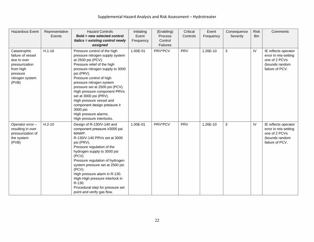
Catastrophic failure of vessel due to over pressurization from high pressure nitrogen system (PVB)
H.1-16 Pressure control of the high pressure nitrogen supply system at 2500 psi (PCV). Pressure relief of the high pressure nitrogen supply to 3000 psi (PRV). Pressure control of high pressure nitrogen system pressure set at 2500 psi (PCV). High pressure component PRVs set at 3000 psi (PRV). High pressure vessel and component design pressure ≥ 3000 psi. High pressure alarms. High pressure interlocks.
1.00E-01 PRV*PCV PRV 1.26E-10 3 IV IE reflects operator error in mis-setting one of 2 PCVs (bounds random failure of PCV.
Operator error – resulting in over pressurization of the system (PVB)
H.2-10 Design of R-130/V-140 and component pressure ≥3000 psi MAWP. R-130/V-140 PRVs set at 3000 psi (PRV). Pressure regulation of the hydrogen supply to 3000 psi (PCV). Pressure regulation of hydrogen system pressure set at 2500 psi (PCV). High pressure alarm in R-130. High-High pressure interlock in R-130. Procedural step for pressure set point and verify gas flow.
1.00E-01 PRV*PCV PRV 1.26E-10 3 IV IE reflects operator error in mis-setting one of 2 PCVs (bounds random failure of PCV.
22

Supplemental Hazard Analysis and Risk Assessment – Hydrotreater
Hazardous Event Representative
Events Hazard Controls
Bold = new selected control Italics = existing control newly
assigned
Initiating Event
Frequency
(Enabling) Process Control Failures
Critical Controls
Event Frequency
Consequence Severity
Risk Bin
Comments
Operator error – failure to open/close valve resulting in catastrophic failure of vessel (PVB)
H.1-11 H.1-21
Procedural Step (including valve lineup). Pressure relief valves on low pressure system components (PRV).
2.00E-02 PRV 4.00E-06 3 IV Relief valves have been sized for this scenario. IE reduced due to requirement of two valves to be misaligned.
Excessive pressure in low pressure nitrogen system resulting in catastrophic failure of the vessel (PVB)
H.1-15 H.2-7 H.2-26 H.4-29 H.4-31B H.7-4
Pressure regulation of the low pressure nitrogen supply to 100 psi (PCV) Pressure regulation of the low pressure nitrogen system pressure to 10 psi (PCV). Low pressure component PRVs set at ≤ 100 psi (PRV). Pressure test procedure Design of V-160 A/B 155 psi V-160 A/B PRV set at 70 psi. Containment pan on skid /enclosure. Design V-125 155 psi MAWP, V-125 PRV set at ≤ 100 psi (PRV) Low pressure system pressure limit. Pressure set point, system pressure control. Enclosure Design – Class 1 Division 2. Enclosure ventilation system Flammable vapor monitoring on skid. Fire suppression system in enclosure.
1.00E-01 PRV*PCV PRV 1.26E-10 3 IV IE reflects operator error in mis-setting one of 2 PCVs (bounds random failure of PCV.
23

Supplemental Hazard Analysis and Risk Assessment – Hydrotreater
Hazardous Event Representative
Events Hazard Controls
Bold = new selected control Italics = existing control newly
assigned
Initiating Event
Frequency
(Enabling) Process Control Failures
Critical Controls
Event Frequency
Consequence Severity
Risk Bin
Comments
Catastrophic failure of vessel due to ISCO pump failure results in liquid backflow (PVB)
H.4-1 PSE2005 @ 100 psi sized for backflow (PRV). Check valve, CK-2007 and CK-2012 (CV).
2.00E-02 CV*CV PRV 7.67E-09 3 IV IE reduced due to requirement of multiple failures in ISCO pump
Catastrophic failure of vessel due to valve failure/ over pressurization (PVB)
H.4-22 PSV-4016 set at 70 psi (PRV). LG-147 designed at 100 psig MAWP. LG-147 vented to product gas header. PSV-5001 in product gas vent header downstream of LG-147 is set at 10 psi (PRV).
1.00E-01 PRV*PRV 4.00E-09 3 IV
Catastrophic failure of vessel due to a fast block in flow path (PVB) (bounds spray or spill)
H.3-2 H.3-3 H.3-4 H.4-17 H.4-27 U-1 U-2 U-21
Design of V-140 -3000 psi MAWP. Pressure relief valve PSV -4002 set at 3000 psi (PRV). PRV in reactor PSV-3011 (PRV) Level control on V-140 (indicator/alarm). Pressure indicators and alarms. Over pressurization controls from reactor (P2). H/H interlock to ISCO pump Switch to tempered water
1.00E-01 P2 PRV*PRV
2.40E-10
3 IV Conservative ignores process indicators- assumed fast acting. Would require additional failure (P2) to challenge pressure boundary.
24

Supplemental Hazard Analysis and Risk Assessment – Hydrotreater
Hazardous Event Representative
Events Hazard Controls
Bold = new selected control Italics = existing control newly
assigned
Initiating Event
Frequency
(Enabling) Process Control Failures
Critical Controls
Event Frequency
Consequence Severity
Risk Bin
Comments
Catastrophic failure of vessel due to a slow block in flow path (PVB)
H.4-12 H.4-13 H.4-16 H.4-21 U-26
L/L mas flow alarm and an interlock to shut off hydrogen and ISCO pump (OP2) Procedural monitoring of system Sufficient time for operator response Process indicators Design of high pressure components Pressure Relief Valve PSC-4002 (PRV) Level control on V-140. Pressure indicators and alarms (OP2)
1.00E-01 OP2 PRV 1.00E-06 3 IV
25

Supplemental Hazard Analysis and Risk Assessment – Hydrotreater
Hazardous Event Representative
Events Hazard Controls
Bold = new selected control Italics = existing control newly
assigned
Initiating Event
Frequency
(Enabling) Process Control Failures
Critical Controls
Event Frequency
Consequence Severity
Risk Bin
Comments
Failure of vessel material or piping system leading to flammable atmosphere
H.4-8 H.4-15 H.4-19 H.4-20 H.7-8
R-130 Design Procedural step: vessel inspection, preventative maintenance and pressure test Steam impingement shield/pathway (Graylock and expanded metal screen/ acrylic shield on walkway north side of flange). Overpressure over-temperature alarms and controls Enclosure design – Class 1 Division 2 Enclosure ventilation system (VENT) Hydrogen monitors on skid and in enclosure . Flammable vapor monitor on skid Thermowell is replaceable Robust design for glass Design of high pressure components Design V-125 155 psi MAWP, V-125 PRV set at ≤ 100 psi. Minimize time in enclosure (OP1)
1.00E-02 IGN2(EN) VENT 5.00E-06 3 IV IE due to leak in vessel set at LK2 bounds LK3 Ignores gas detection (sudden event).
5.00E-03 OP1 5.00E-04 2 IV Flashing steam event; IE frequency reflects required orientation of spray and proximity of operator. Recommendation: evaluate use of PPE for protection against steam release events.
26

Supplemental Hazard Analysis and Risk Assessment – Hydrotreater
Hazardous Event Representative
Events Hazard Controls
Bold = new selected control Italics = existing control newly
assigned
Initiating Event
Frequency
(Enabling) Process Control Failures
Critical Controls
Event Frequency
Consequence Severity
Risk Bin
Comments
Gasket failure leading to flammable atmosphere
H.4-26 H.4-28
Design of vent system. Procedural step calibration of WTM. Enclosure design – Class 1 Division 2 Enclosure ventilation system (VENT). Hydrogen monitors on skid and in enclosure. Flammable vapor monitor on skid (GD). Fire suppression system in enclosure. Containment pan on skid and by the enclosure. Pressure test procedure. Design of V-160 A/B and piping. Drains are double valved, valved and capped, or valve and quick disconnect. Personal Oxygen/ Gas Detectors would notify operators of release
1.00E-01 IGN2(EN) GD*VENT 2.65E-06 3 IV IE - LK1 leak from seal Included GD
Operator error –failure to close a valve before opening another resulting in flammable atmosphere
H.6-1 HV-2018 Action: Replace T upstream HV-2009 with 3-way valve. Check Valve (CK-2007) Procedural step.
1.00E-01 Prevented with 3-way valve
Prevented NA I.E.F. due to operator error Event prevented due to design change
27

Supplemental Hazard Analysis and Risk Assessment – Hydrotreater
Hazardous Event Representative
Events Hazard Controls
Bold = new selected control Italics = existing control newly
assigned
Initiating Event
Frequency
(Enabling) Process Control Failures
Critical Controls
Event Frequency
Consequence Severity
Risk Bin
Comments
Operator error –failure in procedure resulting in flammable atmosphere
H.1-8 H.1-12 H.1-14 H.2-9
Pressure test procedures (detection of no pressure on system components). Hydrogen monitors on skid and in enclosure (GD) Enclosure Design – Class 1 Div 2 (IGN1(EN)). Enclosure Ventilation System (VENT). Flammable vapor monitor on skid Low pressure alarm – R-130.
1.00E-01 IGN1(EN)* LK1
VENT
1.00E-07 3 IV
High pressure spray of (jet flame) combustible liquid and potential flammable atmosphere creation may be mitigated by steam.
Operator error – failure to close valve (HV-2009) resulting in creation of spill/spray of flammable liquid
H.2-17 H.7-9
Procedural check that drain valve is closed. Enclosure Design – Class 1 Division 2. Enclosure ventilation. Containment for skid. Personal Oxygen/ Gas Detectors would notify operators of release.
1.00E-01 IGN1(EN) 1.00E-04 2 IV Used lower value for IGN1(EN) due to small size of spill & ventilation H.2-17 assumes 3-way valve turned to bypass condition.
Operator error- failure to purge resulting in flammable atmosphere
H.8-2 H.8-3
Pressure indicator on reactor. Procedural step: verify zero energy- and hold point. Enclosure ventilation system (VENT). Flammable vapor monitor on skid (GD). Hydrogen monitor on skid and in enclosure (GD).
1.00E-01 IGN2(EN) VENT*GD
2.65E-06 2 IV Defines transition to non-Class 1/Div 2 (H.8-3). Nitrogen flush performed prior to disassembly (possibly between step 6 & 7).
28

Supplemental Hazard Analysis and Risk Assessment – Hydrotreater
Hazardous Event Representative
Events Hazard Controls
Bold = new selected control Italics = existing control newly
assigned
Initiating Event
Frequency
(Enabling) Process Control Failures
Critical Controls
Event Frequency
Consequence Severity
Risk Bin
Comments
Operator error – failure to connect lines resulting in flammable atmosphere
H.5-2 H.7-5
Design of quick disconnects (closed unless properly engaged)(QD). Enclosure design – Class 1 Div 2 (IGN1(EN)). Enclosure ventilation. Containment for skids and enclosure. Flammable vapor monitoring on skid. Fire suppression system in enclosure. Procedural step: Connect vent line prior to nitrogen outlet.
1.00E-01 IGN1(EN)* QD
2.10E-05 2 IV QD failure bounds line failures.
Operator error – failure to establish and maintain Class 1 Div 2 environment
H.2-1 H.2-2 H.2-3
Procedural steps: pressure test, use of anti-sparking tools, initiate purge. Enclosure ventilation system (VENT). Hydrogen monitors on skid and in enclosure. Flammable vapor monitor on skid. Pressure monitoring/alarms on cabinets and furnace enclosure.
1.00E-01 LK1* IGN2(EN)
VENT 5.00E-06
2 IV
Operator error – closure of HV-2006 resulting in spray of flammable liquid
H.2-15 H.7-7
Transfer line (tubing) rated at 4800 psi (LK2). ISCO pump high pressure set point (process controlled)(P2). ISCO pump firmware maximum pressure of 3750 psi (P2). ISCO pump shear pin at 4500 psi (P2).
1.00E-01 IGN2(EN)*P2*LK2
3.00E-05 2 IV Requires additional failure (P2) to challenge pressure boundary
29

Supplemental Hazard Analysis and Risk Assessment – Hydrotreater
Hazardous Event Representative
Events Hazard Controls
Bold = new selected control Italics = existing control newly
assigned
Initiating Event
Frequency
(Enabling) Process Control Failures
Critical Controls
Event Frequency
Consequence Severity
Risk Bin
Comments
Failure of pressure boundary (PCV-4007) resulting in flammable atmosphere
H.4-23 H.4-24
The badger valve (PV-4005) would try to control the pressure (PCV). PSV-5001 set at 10 psi (PRV). Vent system flow path design (1/2 or greater SS tubing). Low alarm at PIT-4005 and PIT-3001. Design of vent system. Enclosure Design – Class 1 Div 2. Enclosure ventilation system.
1.00E-01 IGN2(EN)* PCV
PRV 3.14E-07 3 IV IE due to operator error (open bypass)
Operational upset from other PDL-West operations leading to flammable atmosphere in PDL
U-31
Operational restriction on crane use Excess flow valve on gas supply (EFV)
1.00E-03
IGN2(EN)
EFV
6.50E-06
3 IV IE based on Admin control on crane to restrict usage during hydrotreater operation
Operational upset from other PDL-West operations leading to flammable atmosphere in enclosure
U-32
Flammable vapor monitor Enclosure Design – Class 1 Division 2 MCA alarm, 20 minute bypass timer until Scenario A is initiated (unless operator bypasses)
1.00E-01 IGN1(EN) GD 5.30E-06 3 IV Lower frequency used for IGN1(EN) due to concentration of flammable gas being drawn into enclosure.
30

Supplemental Hazard Analysis and Risk Assessment – Hydrotreater
Hazardous Event Representative
Events Hazard Controls
Bold = new selected control Italics = existing control newly
assigned
Initiating Event
Frequency
(Enabling) Process Control Failures
Critical Controls
Event Frequency
Consequence Severity
Risk Bin
Comments
Hydrogen leak resulting in flammable atmosphere
U-24
Design of hydrogen pipe system (one piece of tubing (~17 ft) rated at maximum pressure; Located in a tray sitting in a tube holder supported across the length. It is a 13 foot elevation, in a tray, protected from edge of building. Excess flow valve on hydrogen supply (catastrophic break) (EFV) Makeup air unit for enclosure. Passive PDL roof vents (PDL)
2.93E-06
IGN2(EN)
EFV 1.90E-08 3 IV IE set at PC1 assuming catastrophic pipe failure
2.93E-05 IGN2(EN)
PDL 1.47E-06 3 IV IE reflects a PC1 leak that is large enough to pose concern but small enough to not be detectable by operators or activate EFV. Smaller leaks pose a concern similar to other users of hydrogen (addressed within HDI/SMPs) and would most likely not reach significant concentrations due to passive PDL roof vents
Failure in ventilation resulting in flammable atmosphere
U-3 U-4 U-5 U-6
Exhaust flow switch initiates Scenario A on loss of flow Design of stack Loss of ventilation fan trips process controls
1.00E-01 IGN1(EN)* LK1
P3 1.00E-06 2 IV
Activation of pressure relief resulting in flammable atmosphere
U-8 Design of knockout pot and lines 1.47E-02 IGN3(EN) 1.47E-05 1 IV IE based on relief flow path open to atmosphere, personnel impacts not expected.
31
Supplemental Hazard Analysis and Risk Assessment – Hydrotreater
Hazardous Event Representative
Events Hazard Controls
Bold = new selected control Italics = existing control newly
assigned
Initiating Event
Frequency
(Enabling) Process Control Failures
Critical Controls
Event Frequency
Consequence Severity
Risk Bin
Comments
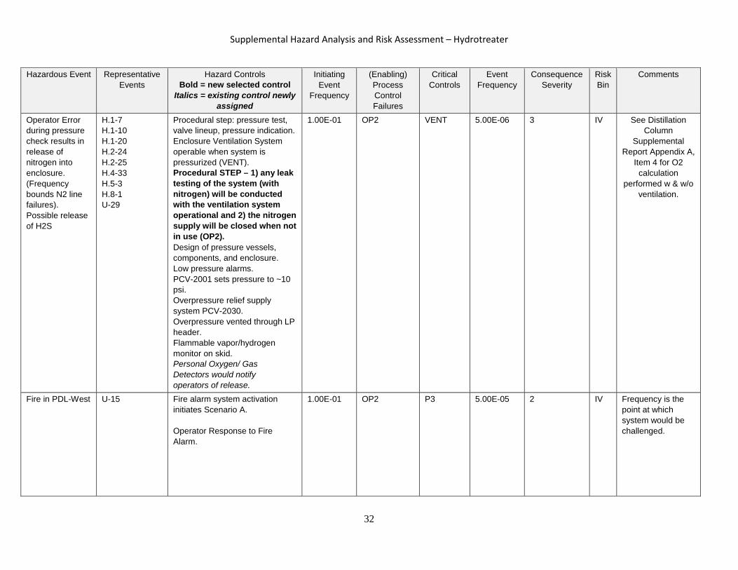
Operator Error during pressure check results in release of nitrogen into enclosure. (Frequency bounds N2 line failures). Possible release of H2S
H.1-7 H.1-10 H.1-20 H.2-24 H.2-25 H.4-33 H.5-3 H.8-1 U-29
Procedural step: pressure test, valve lineup, pressure indication. Enclosure Ventilation System operable when system is pressurized (VENT). Procedural STEP – 1) any leak testing of the system (with nitrogen) will be conducted with the ventilation system operational and 2) the nitrogen supply will be closed when not in use (OP2). Design of pressure vessels, components, and enclosure. Low pressure alarms. PCV-2001 sets pressure to ~10 psi. Overpressure relief supply system PCV-2030. Overpressure vented through LP header. Flammable vapor/hydrogen monitor on skid. Personal Oxygen/ Gas Detectors would notify operators of release.
1.00E-01
OP2
VENT
5.00E-06
3 IV See Distillation Column
Supplemental Report Appendix A,
Item 4 for O2 calculation
performed w & w/o ventilation.
Fire in PDL-West U-15 Fire alarm system activation initiates Scenario A. Operator Response to Fire Alarm.
1.00E-01 OP2 P3 5.00E-05 2 IV Frequency is the point at which system would be challenged.
32
Supplemental Hazard Analysis and Risk Assessment – Hydrotreater
Hazardous Event Representative
Events Hazard Controls
Bold = new selected control Italics = existing control newly
assigned
Initiating Event
Frequency
(Enabling) Process Control Failures
Critical Controls
Event Frequency
Consequence Severity
Risk Bin
Comments
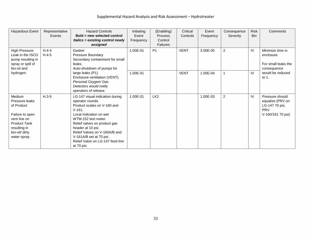
High Pressure Leak in the ISCO pump resulting in spray or spill of bio-oil and hydrogen.
H.4-4 H.4-5
Gasket Pressure Boundary Secondary containment for small leaks. Auto-shutdown of pumps for large leaks (P1). Enclosure ventilation (VENT). Personal Oxygen/ Gas Detectors would notify operators of release.
1.00E-01
P1 VENT
3.00E-05
2
IV
Minimize time in enclosure. For small leaks the consequence would be reduced to 1.
1.00E-01 VENT 1.00E-04 1 IV
Medium Pressure leaks of Product Failure to open vent line on Product Tank resulting in bio-oil/ dirty water spray.
H.3-5
LG-147 visual indication during operator rounds. Product scales on V-160 and V-161. Local indication on wet WTM-152 test meter. Relief valves on product gas header at 10 psi. Relief Valves on V-160A/B and V-161A/B set at 70 psi. Relief Valve on LG-147 feed line at 70 psi.
1.00E-01 LK2 1.00E-03 2 IV Pressure should equalize (PRV on LG-147 70 psi, PRV V-160/161 70 psi)
33

Supplemental Hazard Analysis and Risk Assessment – Hydrotreater
Hazardous Event Representative
Events Hazard Controls
Bold = new selected control Italics = existing control newly
assigned
Initiating Event
Frequency
(Enabling) Process Control Failures
Critical Controls
Event Frequency
Consequence Severity
Risk Bin
Comments
Low Pressure leaks of bio-oil/sulfiding agent
H.1-13 H.1-22 H.1-23 H.1-24 H.1-25 H.1-28 H.2-8 H.2-16 H.2-22 H.2-23
Procedural step (OP2) Secondary Containment Air system pressure set at 100 psi. Filters rated at 250 psi V-120 rated at 135 psi PRV set at 70 psi Transfer line rated at >3000 psi V-120 level indicator High-High interlocks Bypass system Vessel Design
1.00E-02 OP2 5.00E-04
2 IV Secondary containment and enclosure ventilation. PPE will further reduce consequence. IE reflects significant leak/spray from pressurized system. For failure associated with open lines consequence would be 1.
Low Pressure leaks of Aqueous (water by-product)
H.4-31a H.4-32
Pressure test procedure (OP2) Vessel and piping design Quick disconnect Containment
1.00E-02 OP2 5.00E-04
1 IV Secondary containment and enclosure ventilation. PPE will further reduce consequence.
34

Supplemental Hazard Analysis and Risk Assessment – Hydrotreater
Hazardous Event Representative
Events Hazard Controls
Bold = new selected control Italics = existing control newly
assigned
Initiating Event
Frequency
(Enabling) Process Control Failures
Critical Controls
Event Frequency
Consequence Severity
Risk Bin
Comments
Catastrophic failure of vessel given inability of pressure relief due to blocked low pressure flow path
U-7 Administrative controls to check relief header – Modify the SOP to require verification that the low pressure relief line is free of obstruction Design of system includes bird screens, double release path at top. Design pressure of knockout pot is 12 psi.
1.00E-02 PROCESS* OP2
5.00E-06 3 IV IE due to blocked flow path (e.g., mud daubers). Event frequency requires multiple failures to correct the blockage and upset/failures (0.01) resulting in activation of PRV. Failure point is most likely in low pressure portion of system- in LP header (knockout pot or stack)
35
Supplemental Hazard Analysis and Risk Assessment – Hydrotreater
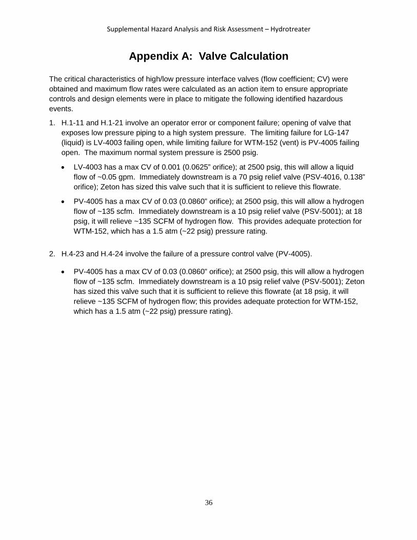
Appendix A: Valve Calculation
The critical characteristics of high/low pressure interface valves (flow coefficient; CV) were obtained and maximum flow rates were calculated as an action item to ensure appropriate controls and design elements were in place to mitigate the following identified hazardous events.
1. H.1-11 and H.1-21 involve an operator error or component failure; opening of valve that exposes low pressure piping to a high system pressure. The limiting failure for LG-147 (liquid) is LV-4003 failing open, while limiting failure for WTM-152 (vent) is PV-4005 failing open. The maximum normal system pressure is 2500 psig.
• LV-4003 has a max CV of 0.001 (0.0625” orifice); at 2500 psig, this will allow a liquid flow of ~0.05 gpm. Immediately downstream is a 70 psig relief valve (PSV-4016, 0.138” orifice); Zeton has sized this valve such that it is sufficient to relieve this flowrate.
• PV-4005 has a max CV of 0.03 (0.0860” orifice); at 2500 psig, this will allow a hydrogen flow of ~135 scfm. Immediately downstream is a 10 psig relief valve (PSV-5001); at 18 psig, it will relieve ~135 SCFM of hydrogen flow. This provides adequate protection for WTM-152, which has a 1.5 atm (~22 psig) pressure rating.
2. H.4-23 and H.4-24 involve the failure of a pressure control valve (PV-4005).
• PV-4005 has a max CV of 0.03 (0.0860” orifice); at 2500 psig, this will allow a hydrogen flow of ~135 scfm. Immediately downstream is a 10 psig relief valve (PSV-5001); Zeton has sized this valve such that it is sufficient to relieve this flowrate {at 18 psig, it will relieve ~135 SCFM of hydrogen flow; this provides adequate protection for WTM-152, which has a 1.5 atm (~22 psig) pressure rating}.
36

Supplemental Hazard Analysis and Risk Assessment – Hydrotreater
Appendix B. Chemical Safety Data Sheets
Chemical Name Safety Data Sheet (SDS)
Di-tert-butyl disulfide SDS-DTBS
Decane SDS-Decane
Acetone SDS-Acetone
37