user manual - mclane labsmclanelabs.com/.../uploads/2010/05/mclane-pps.manual.rev_.13.c.1… · 1-2...
TRANSCRIPT

Phytoplankton System User Manual
2017 McLane Research Laboratories, Inc., Rev.10.C.17
Tel: +1 (508) 495-4000 Skype: mclane_research [email protected] www.mclanelabs.com

1-1
Chapter 1 Introduction and System Description
McLane Phytoplankton Sampler (PPS) The McLane Phytoplankton Sampler (PPS) is an autonomous time-series particulate
sampler that filters up to 24 individual water samples through 47mm filters. Samples are collected
by user-defined time-series events. The multi-port valve keeps samples separate and pumps water
directly onto the filter before passing through a 50, 125, or 250 ml/min pump. The maximum
volume is 10L per filter, 250L total volume. The data recorded during a deployment includes
flow rates, volume pumped, pump feedback, power, temperature and event times. This data is
offloaded from the PPS after deployment and used for sample analysis.
PPS Options
Optional PPS features include:
• Fixative Valve – provides a secondary system intake and exhaust path that can be
used to flood a filter holder with fixative after a sample is collected.
• Antifouling Solution Reservoir – A 500 ml reservoir plumbed to port 24 is used to
supply a post-sample flush with antifouling fluid of the user’s choice to prevent
biofouling between sample events.
Using this Manual This User Manual provides:
• Descriptions and specifications of mechanical and electrical parts of the system.
• Operating instructions.
• Suggested maintenance procedures to extend sampler performance.
This user manual is designed to provide support from the first steps of powering on and
communicating with the instrument, to the final steps of recovering data from a recently
deployed system, and storing the instrument. Sampler operators and technicians should
read this manual and keep a copy as a reference.
1-2
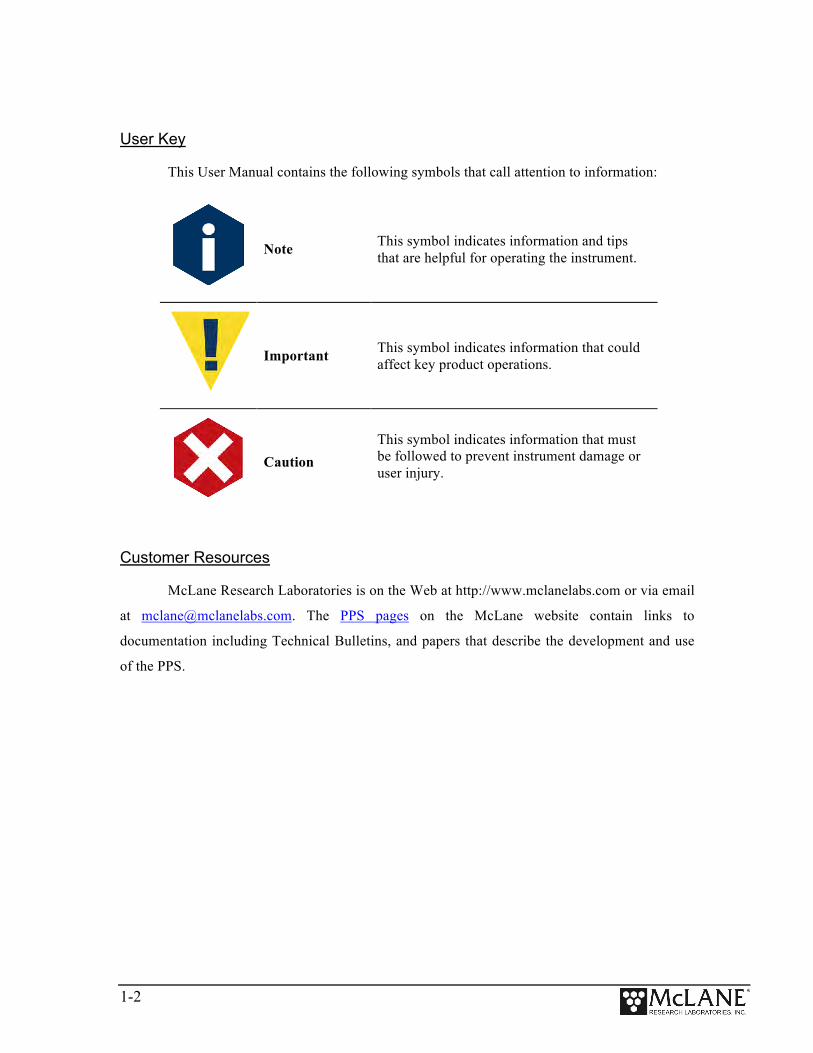
User Key
This User Manual contains the following symbols that call attention to information:
Note This symbol indicates information and tips that are helpful for operating the instrument.
Important This symbol indicates information that could affect key product operations.
Caution This symbol indicates information that must be followed to prevent instrument damage or user injury.
Customer Resources
McLane Research Laboratories is on the Web at http://www.mclanelabs.com or via email
at [email protected]. The PPS pages on the McLane website contain links to
documentation including Technical Bulletins, and papers that describe the development and use
of the PPS.

1-3
Technical Support
When contacting McLane for technical support, please provide the following:
• Firmware version and instrument serial number. Serial number is printed on a
label attached to the controller housing and on the Contact screen,
(Figure 1-1). Serial number also displays on the Main Menu screen.
• A description of the problem.
• A text file of data created using the Motocross file capture utility.
Figure 1-1: McLane Contact Information
Instrument Training
McLane also offers a 1 day PPS training course at our facility free of charge with the
purchase of a new instrument. Participants conduct trial deployments and work directly with
members of the McLane engineering staff. Conducting trial deployments is a beneficial way to
learn system operations before actual field investigations. For more product training information
refer to www.mclanelabs.com.
Selection [] ? 8 McLane Research Laboratories, Inc. Falmouth Technology Park 121 Bernard East Saint Jean Drive East Falmouth, MA 02536-4444 USA Email: [email protected] Web: http://www.McLaneLabs.com Tel: 508-495-4000 Fax: 508-495-3333 Configuration: WTS-125M-SV Source file: CF2-2.05.c Electronics S/N: ML12345-03 Compiled: May 9 2016 14:09 Press any key to continue.
1-4
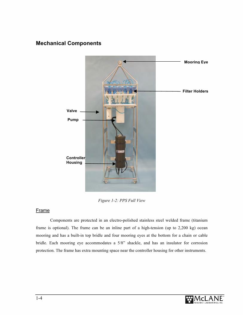
Mechanical Components
Figure 1-2: PPS Full View
Frame
Components are protected in an electro-polished stainless steel welded frame (titanium
frame is optional). The frame can be an inline part of a high-tension (up to 2,200 kg) ocean
mooring and has a built-in top bridle and four mooring eyes at the bottom for a chain or cable
bridle. Each mooring eye accommodates a 5/8” shackle, and has an insulator for corrosion
protection. The frame has extra mounting space near the controller housing for other instruments.
Mooring Eye
Filter Holders
Valve
Pump
Controller Housing

1-5
Controller Housing
The PPS controller housing is a heat-treated aluminum alloy cylinder, rated to a depth of
5,500m. The housing holds the battery and electronics. Chapter 2 of this User Manual contains
detailed instructions for opening the controller housing. Follow these instructions and the
recommended safety precautions when opening the controller housing.
Figure 1-3: Controller Housing

1-6
Top and Bottom End Caps
The battery and electronics are fastened to the inside of the controller housing top end
cap. See Figure 1-5 for detailed information about the top end cap.
Though unlikely, an unsafe internal controller housing pressure is possible,
resulting from the chemical reaction between alkaline electrolyte and anodized
aluminum due to battery failure with or without the intrusion of seawater. There
can be enough pressure to cause the endcap bolts to fail, especially when one or
more are loosened or removed.
O-Rings
Each end cap includes two 70 durometer round section o-rings (2-246 and 2-242) and one
90 durometer backup ring (8-242). O-rings and surfaces should be regularly cleaned with
isopropyl alcohol. O-rings should be lubricated with provided Parker O-Lube and replaced when
necessary. The toolkit has spare O-rings. More o-rings can be purchased from McLane.
O-ring maintenance and correct placement is critical to keep the controller
housing end caps from water intrusion. Incorrect o-ring placement results in
cracks that could void the sampler warranty.
Before sealing the controller housing, confirm the o-rings are seated in the radial grooves.
Check to ensure there is no foreign material, cracks, or grit, sand or hair present. Clean o-rings
with alcohol and lubricate with a thin coating of o-ring grease before deployment.
Figure 1-4: O-Ring Installation
O-ring Installation

1-7
End Cap Bulkhead Connectors
The end cap has bulkhead connectors for the Communications connector, Pump, and
Valve (Figure 1-5). The bulkhead assignment (P, V, C) is etched into the end cap. A zinc anode
is attached to each end on the controller housing end cap to prevent corrosion. Spare zincs are
included in the toolkit.
Figure 1-5: Controller Housing End Cap Bulkhead Connectors
Pressure Relief Valve
Attention and care should be taken in maintaining, operating, and opening the pressure
housing. All PPS systems shipped after summer 2015 have a pressure relief valve (PRV) on the
controller housing.
Bolt Lock Washer Flat Washer Plastic Insulator
Zinc anode
Pump connector
Communication connector
Valve connector
Pressure relief valve
Bolt Lock Washer Flat Washer Plastic Insulator

1-8
Pressure Relief Valve Upgrade
McLane offers a Pressure Relief valve upgrade retrofit for all controller
housings (includes installation, not including shipping and insurance costs).
The end-cap and anodizing must be in suitable condition for PRV retrofits.
Contact [email protected] for more information about the PRV retrofit.

1-9
25-Port Valve
The PPS dual-head, 25-port rotary valve directs water through 24 individual filters at
programmed times during a deployment. The top head has a single intake port and 25 exhaust
ports, and the bottom head has 25 intake ports and a single exhaust port. An optical sensor and
slotted disk determine rotor position. The motor, gear head, and optical sensor are in a pressure
compensated PVC plastic housing filled with Dow Corning 200 fluid (200cSt.). The valve top
shows the port numbers, and the rotor position indicator points to the currently aligned port. The
filter holders are connected between two valve heads. One port is open on each head at one time.
Figure 1-6: Valve Pump
The PPS can have a 50, 125, or 250 ml/min positive displacement graphite gear pump
installed. The pump head is type 316 stainless steel and has user replaceable carbon gears and
magnet. A brushless DC 3-phase motor is magnetically coupled to the pump head, and driven by
an algorithm designed to limit differential pressure at filters while maximizing battery life.
Figure 1-7: Pump Head Gear and Replaceable Magnet
Valve Intake
Home Port
Pump Head

1-10
Filter Holders
The PPS collects samples on twenty-four 47 mm filter holders. Each filter holder is
connected in series between the intake head (top half of the valve) and the exhaust head (lower
half of the valve). The pump draws water out from the bottom of the filter creating a pressure
gradient that pulls ambient seawater into the filter holder and through the filter. After each sample
is taken, the valve returns to Home Port (Port 0), and seals the sample in the filter holder.
Figure 1-8: Filter Holders
Home Port Water Flush
Home Port (Port 0) can be used to flush standing water from the valve intake tube and
valve heads before each sample is collected. This water flush prevents sample contamination and
reduces accumulated bio-fouling. A filter assembly with a 25mm filter holder holds a filter with a
pore size between 3 and 20 microns to prevent large suspended particles from entering the pump
while the valve is being flushed. Replace this filter before every deployment.
Figure 1-9: Water Flush Filter Holder
Water Flush Filter Holder (Port 0)
1-11
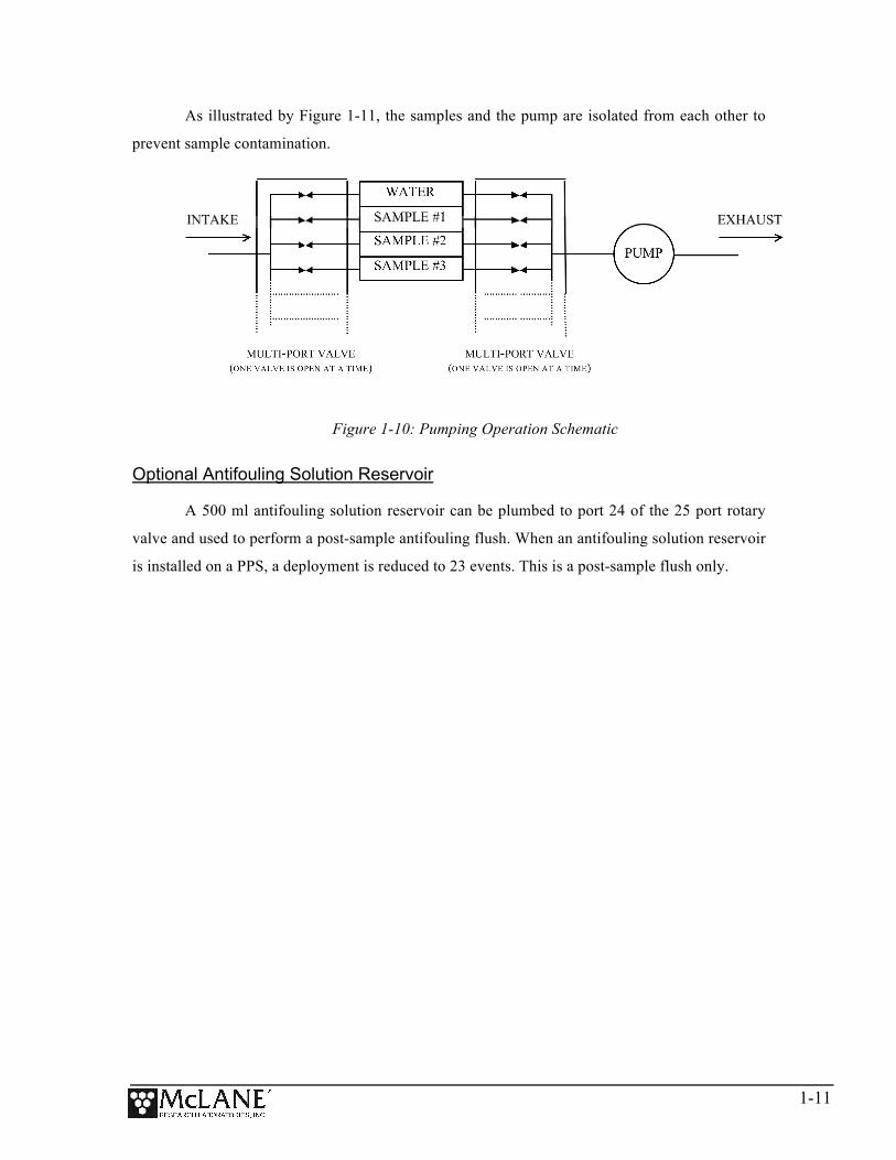
As illustrated by Figure 1-11, the samples and the pump are isolated from each other to
prevent sample contamination.
Figure 1-10: Pumping Operation Schematic
Optional Antifouling Solution Reservoir
A 500 ml antifouling solution reservoir can be plumbed to port 24 of the 25 port rotary
valve and used to perform a post-sample antifouling flush. When an antifouling solution reservoir
is installed on a PPS, a deployment is reduced to 23 events. This is a post-sample flush only.

1-12
Optional Fixative Valve
The optional fixative valve offers a secondary intake and exhaust fluid path to the PPS
that can be used to flood filter holders with fixative immediately after a sample is taken. The dual
Fixative valve is made of two manifold mount three-way isolation valves:
• One valve isolates water and fixative intake paths.
• The other valve isolates water and fixative exhaust paths.
The fixative and sample water intake and exhaust paths are labeled on the Fixative valve
and share a common system intake and exhaust path to and from the 25 port valve. PPS systems
with the Fixative Valve option are shipped with one 2 liter fixative reservoir bag and one 2 liter
exhaust collection bag installed inside of a fixative box. Different fixative bag sizes can be
configured in the firmware. The exhaust bag must be the same size as the intake bag, or larger.
Fixative flushes, plumbing and fixative valve operation are described in this User Manual.
Figure 1-11: PPS with Dual Fixative Valve Option
Fixative Box
Fixative Valve (Optional)
1-13
The fixative valve option can be added to a CF2-based PPS. Contact
[email protected] for information about this retrofit.
PPS Toolkit
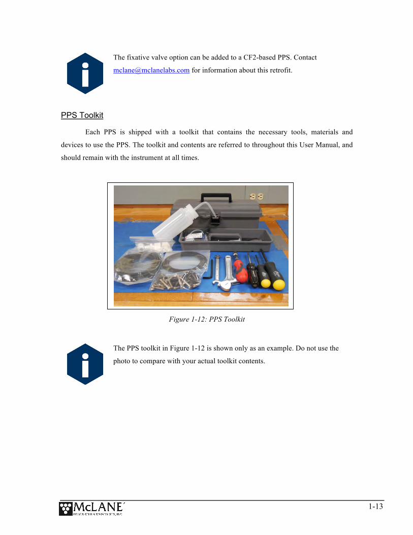
Each PPS is shipped with a toolkit that contains the necessary tools, materials and
devices to use the PPS. The toolkit and contents are referred to throughout this User Manual, and
should remain with the instrument at all times.
Figure 1-12: PPS Toolkit
The PPS toolkit in Figure 1-12 is shown only as an example. Do not use the
photo to compare with your actual toolkit contents.

1-14
Serial Number
The white plastic base plate contains a serial number label. The controller housing end
cap, pump assembly, valve assembly, and system menu also display the serial number.
Electronics Components The PPS firmware runs on the Persistor CF2 microcontroller. Older PPS systems use the
TattleTale 8 (TT8) microcontroller. The TT8 was discontinued, and McLane instruments now use
the CF2. While most of this User Manual can apply to both current and older McLane
instruments, significant firmware, hardware, and procedural changes have been made to the PPS
with the CF2 microcontroller and some sections will not apply to older systems.
Contact [email protected] for information about upgrading from the
TT8 to the CF2 microcontroller. McLane recommends this upgrade. We offer
only limited support on devices that use the TT8 microcontroller.
McLane electronics are designed to use minimal power while achieving the longest
possible deployment durations. Instrument electronics spend most of their time in low power
sleep mode. In this suspended state, the system consumes very little power (micro-amps) while
keeping track of time to start and complete scheduled events.
The PPS electronics communicate using RS-232 serial communications and a terminal
emulator. A communications cable included in the toolkit connects the PPS controller with a
computer. Computers that do not have a built-in RS-232 serial port use a USB to RS-232
converter that is also included in the toolkit.
Figure 1-13: USB Communications

1-15
Communications Bulkhead Connector Styles
The communications cable bulkhead connector (connection to the sampler) is a 5-pin
MCBH style. Some older instruments may have a 3-pin XSG style bulkhead connector.
Figure 1-14: Communications Cable Connector Style

1-16
Main Battery
Depending on the PPS manufacture date, the battery style could have a battery holder for
user replaceable ‘D’ cell alkaline batteries as shown in Figure 1-16 or a battery pack as shown in
Figure 1-17.
If using the battery holder with user replaceable drop-in ‘D’ cell batteries, be sure to
install the batteries with the correct orientation in the holder terminals. An instructional video
showing drop in battery replacement is shown on the PPS video pages at www.mclanelabs.com.
Figure 1-15: Drop-in Battery Holder for ‘D’ Cell Batteries
Figure 1-16: A21-1000 Battery Pack
Both battery styles deliver approximately the same power, a nominal voltage of 31.5
VDC. The instrument can perform pump and valve operations while the system voltage is above
18 VDC. When the system voltage drops below 18 VDC, the instrument will enter low power
sleep mode, and when awake, only limited functions will be available at the Main Menu.

1-17
Always take standard electrostatic discharge (ESD) precautions when handling
the electronics.
Backup Battery
After the spring of 2015, new McLane CF2-based instruments no longer require a backup
battery. Prior to this change, the backup batteries served as a voltage source for the electronics
while in low power sleep mode. Electronics hardware changes made the backup battery
unnecessary, and it was eliminated.
If using an older PPS system, check for backup batteries. If your system has backup
batteries, be sure to replace them before each deployment. On the TT8 microcontroller based
devices, the backup battery was a 9 volt battery mounted beside the electronics. On the Persistor
CF2 microcontroller based devices, the backup battery was two AAA batteries mounted near the
electronics.
Figure 1-17: Backup Battery 9V and AAA Styles (Older Model PPS systems)

1-18
Notes

2-1
Chapter 2 Getting Started with your McLane Sampler
This chapter provides the information that will help you become familiar with your
sampler, connect to a computer, and power on the system. This includes the following:
• Setting up a computer for the sampler.
• Connecting the sampler to a computer.
• Powering on the sampler.
• Waking the sampler from low power sleep.
Section 2.1 Setting up a Computer for the Sampler
You will need a computer and a terminal emulation program to communicate with your
sampler. Ideally, the computer will have a built-in RS-232 serial port. A USB to RS-232 adapter
is included in the sampler toolkit for computers without the built-in serial port. While different
terminal emulators can be used to communicate with McLane instruments, only MotoCross, a
terminal emulator for Windows, can be used to upgrade McLane firmware.
A MotoCross installer is located in the firmware directory of the USB drive shipped with
your system. The MotoCross installer can also be downloaded from the sampler’s Software page
on the McLane website: www.mclanelabs.com.
Motocross is available from other sources, but the version provided by McLane
is programmed with default settings to work with McLane instruments.

2-2
Installing MotoCross
1. Find and double-click the file “Setup_Motocross.exe” on your USB drive (or
directory if you downloaded “Setup_Motocross.exe” from the Mclane website
mclanelabs.com).
2. The installer program will guide you through a series of screens.
3. When prompted to choose a destination for the extracted files, navigate to
C:\Program Files (x86) and create a new folder named MotoCross.
4. When MotoCross is extracted, right-click the executable ‘MotoCrossML’ and
create a shortcut on the desktop for easy access.
Figure 2.1-1: MotoCrossML Setup Wizard Screens 1 and 2

2-3
Figure 2.1-2: MotoCrossML Setup Wizard Screens 3 and 4
Figure 2.1-3: MotoCrossML Setup Wizard Screen 5

2-4
Section 2.2 Connecting the Sampler to a Computer
Communicating with the instrument requires connecting the communications cable to the
computer that has the terminal emulation and configuring the terminal emulation software,
MotoCross.
Connecting a Computer
Connect to the sampler by plugging the communications cable from the communications
bulkhead on the end cap to a computer RS-232 serial port.
For a computer without a built-in RS-232 serial port, locate the USB to RS-232 adapter
included in the sampler toolkit. Using the USB to RS-232 adapter, plug in the USB port, wait for
the drivers to install, and then check the computer’s Device Manager for the new USB Serial
Port. Windows downloads and installs the necessary drivers automatically when the USB to RS-
232 adapter is plugged into a USB port.
Figure 2.2-1: Communications Cable

2-5
Configuring MotoCross Communications Settings
1. From the Windows start menu – search the Control Panel for the device manager.
2. Open the device manager.
3. Scroll down to “Ports (COM & LPT)”.
4. If you are using a USB to RS232 adapter and you see a device named USB Serial
Port, you can verify this is your adapter by unplugging the adapter and waiting
for it to disappear from the device manager COM Port list.
5. If your device is not listed, contact McLane Research Labs
([email protected]) for assistance.
Figure 2.2-2: Device Manager COM Port list
Once you have identified your communication port, you will have the information needed
to configure Motocross communication settings.
1. Select “Communication Settings” from the MotoCross File menu.
2. Enter the following values:
Port : Communications Port # identified in the previous steps.
Baud Rate: 9600
Mx Download Baud: 115200
Parity: None
Data Bits: 8
Stop Bits: 1
Flow Control: None

2-6
Control Character Transmission
All McLane instruments use the control character [CTRL]-[C] to wake from Suspend
mode, navigate the menu system, and cancel operations. The McLane version of MotoCross is
pre-configured to transmit control characters.
MotoCross offers a configurable option to either transmit control characters, or to
perform standard Windows editing functions with CTRL-key combinations. It is possible to
switch to perform standard Windows editing functions with CTRL-key combinations by
accidentally pressing [CTRL]-[SHIFT]. If this switch is made, [CTRL]-[C] will not transmit the
control characters needed to wake McLane instruments from Suspend mode.
Always ensure MotoCross is configured to transmit control characters by selecting “Copy
– Paste Options” from the Edit menu, and confirming the configuration as displayed in
Figure 2.2-5.
Figure 2.2-3: Confirm Motocross Configuration
Creating a Capture File
MotoCross and other terminal emulators have a “Capture” or “Log” feature. It is very
important that all communications to your McLane instruments are captured to file. Capture
files are used for troubleshooting with McLane technical support, and provide a record of your
deployment settings, bench tests, and so on.
Follow these steps to log communications in MotoCross to a file:
1. Select Capture Test > Start from the MotoCross Transfer Menu.
2. Select a location to save the file.

2-7
3. To clear any existing file contents, select ‘Overwrite’. To add to existing file
contents select ‘Append’.
4. When asked to include buffer text, select no.
Figure 2.2-4: Do not include Buffer Text
If MotoCross has been running for a long time, a large buffer can crash the program if it
is included in the buffer. If you must, save data that has already printed to the screen.
1. Use Windows Notepad to create a text file.
2. Copy and paste the data you wish to include.
3. Save and close the file.
4. Start capturing communications to the file you created, Append data to the file
instead of Overwriting data.
Troubleshooting the USB Adaptor
The USB adaptor has LED indicator lights for transmitting and receiving data. Typing
any key in Motocross terminal emulation should be indicated by the LED. If no LED light flashes
on keystrokes, you may have selected the incorrect COM Port. Refer to the section that follows
for instructions on MotoCross setup.

2-8
Section 2.3 Powering on the Sampler
Connecting the battery is the only way to power on the sampler electronics. This step
requires opening the controller housing. Be sure to perform this procedure in a dry area and
familiarize yourself with steps for using the Pressure Relief Valve.
Opening the Controller Housing Equipped with the PRV
Attention and care should be taken in maintaining, operating, and opening the pressure
housing. All samplers shipped after summer 2015 have a pressure relief valve (PRV) on the
controller housing. This valve releases automatically at a pressure differential greater than 10psi.
The PRV style may have a center hole and release tool, or the style may have a flat relief valve
that must be manually pulled out.
Observe safety precautions including removing personnel and objects from the
path of the end-cap when removing the controller housing.
Figure 2.3-1: Releasing Pressure Relief Valve (Flat Style)

2-9
Figure 2.3-2: Releasing Pressure Relief Valve (Style with Release Tool)
As a safety measure, the valve should be manually released prior to opening the
controller housing by following the steps below. Steps for opening a controller housing that does
not have a PRV installed are included at the end of this section. Follow those steps if you
have a controller housing manufactured before 2015 that does not include a PRV.
1. Disconnect the cables from the end cap (if connected).
2. Slowly pull on the pressure relief valve to release any vacuum or built up
pressure in the housing.
3. Loosen each end cap bolt a few turns at a time in a star pattern.
If the end cap separates from the housing as you loosen the bolts, this could
indicate a possible pressure buildup inside of the housing. Stop loosening bolts
and continue to gently pull on the pressure relief valve.
4. Remove and place the end cap hardware somewhere safe. Typically plastic
inserts have a snug fit and will remain in the end cap.
5. Grasp the end cap lip with fingertips and pull the end cap out of the housing
(Figure 2.3-2).
PRV
2-10
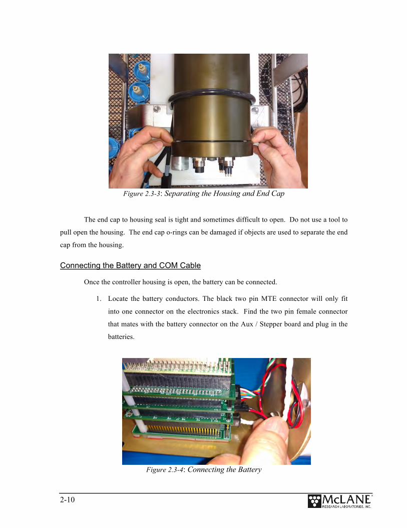
Figure 2.3-3: Separating the Housing and End Cap
The end cap to housing seal is tight and sometimes difficult to open. Do not use a tool to
pull open the housing. The end cap o-rings can be damaged if objects are used to separate the end
cap from the housing.
Connecting the Battery and COM Cable
Once the controller housing is open, the battery can be connected.
1. Locate the battery conductors. The black two pin MTE connector will only fit
into one connector on the electronics stack. Find the two pin female connector
that mates with the battery connector on the Aux / Stepper board and plug in the
batteries.
Figure 2.3-4: Connecting the Battery

2-11
Backup batteries are not installed with firmware v2.05 and higher. Electronics
hardware changes made the backup battery unnecessary and it was elminated. If
deploying a PPS that still has a backup battery, install a fresh battery before
every deployment.
2. Find the communication cable provided in the toolkit.
3. Connect the communications cable to the computer serial communication port
before connecting to the communications connector on the controller end cap.
4. Align the bulkhead connection pins, and push bulkhead in place on the controller
end cap.
Figure 2.3-5: Connecting the COM Cable
5. On the computer, open a properly configured MotoCross window.
6. Connect the DB9 end of the communication cable to the computer
communication port configured in MotoCross.
7. Enter [CTRL]-[C] in MotoCross. If the computer setup procedures were
completed correctly, the Main Menu, a system clock confirmation message, or a
message that indicates the system is Suspended will print to the screen.
2-12
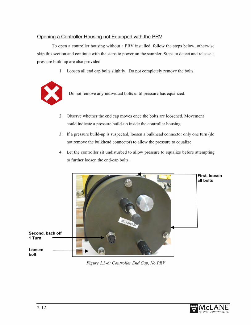
Opening a Controller Housing not Equipped with the PRV
To open a controller housing without a PRV installed, follow the steps below, otherwise
skip this section and continue with the steps to power on the sampler. Steps to detect and release a
pressure build up are also provided.
1. Loosen all end cap bolts slightly. Do not completely remove the bolts.
Do not remove any individual bolts until pressure has equalized.
2. Observe whether the end cap moves once the bolts are loosened. Movement
could indicate a pressure build-up inside the controller housing.
3. If a pressure build-up is suspected, loosen a bulkhead connector only one turn (do
not remove the bulkhead connector) to allow the pressure to equalize.
4. Let the controller sit undisturbed to allow pressure to equalize before attempting
to further loosen the end-cap bolts.
Figure 2.3-6: Controller End Cap, No PRV
Second, back off 1 Turn
Loosen bolt
First, loosen all bolts
2-13
Section 2.4 Waking the Sampler from Low Power Sleep
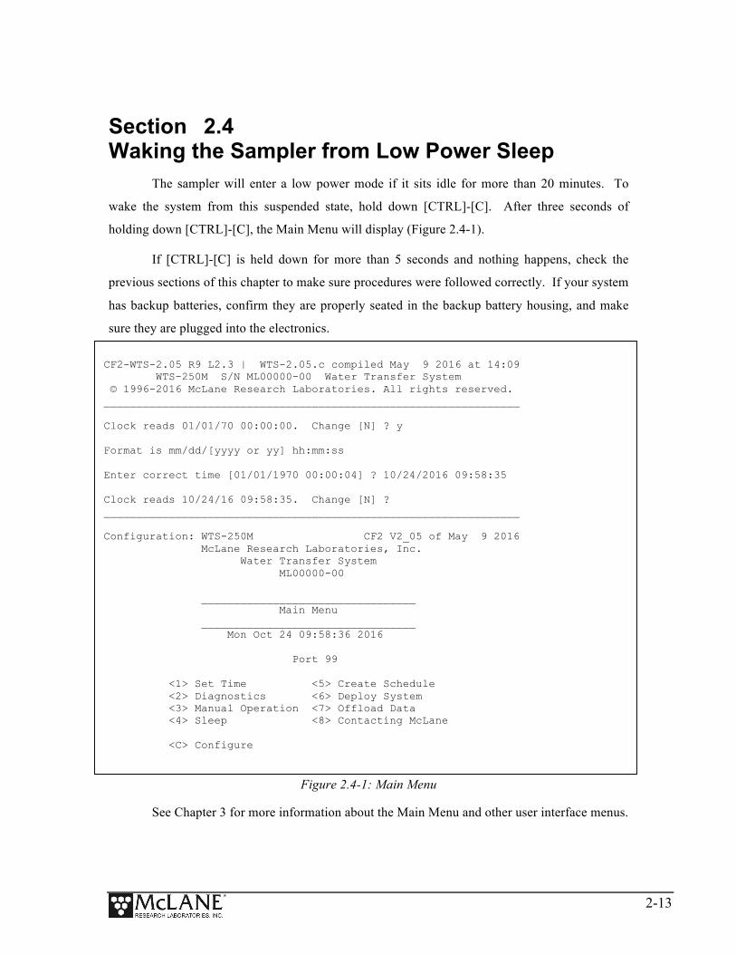
The sampler will enter a low power mode if it sits idle for more than 20 minutes. To
wake the system from this suspended state, hold down [CTRL]-[C]. After three seconds of
holding down [CTRL]-[C], the Main Menu will display (Figure 2.4-1).
If [CTRL]-[C] is held down for more than 5 seconds and nothing happens, check the
previous sections of this chapter to make sure procedures were followed correctly. If your system
has backup batteries, confirm they are properly seated in the backup battery housing, and make
sure they are plugged into the electronics.
Figure 2.4-1: Main Menu
See Chapter 3 for more information about the Main Menu and other user interface menus.
CF2-WTS-2.05 R9 L2.3 | WTS-2.05.c compiled May 9 2016 at 14:09 WTS-250M S/N ML00000-00 Water Transfer System © 1996-2016 McLane Research Laboratories. All rights reserved. ________________________________________________________________ Clock reads 01/01/70 00:00:00. Change [N] ? y Format is mm/dd/[yyyy or yy] hh:mm:ss Enter correct time [01/01/1970 00:00:04] ? 10/24/2016 09:58:35 Clock reads 10/24/16 09:58:35. Change [N] ? ________________________________________________________________ Configuration: WTS-250M CF2 V2_05 of May 9 2016 McLane Research Laboratories, Inc. Water Transfer System ML00000-00 _________________________________ Main Menu _________________________________ Mon Oct 24 09:58:36 2016 Port 99 <1> Set Time <5> Create Schedule <2> Diagnostics <6> Deploy System <3> Manual Operation <7> Offload Data <4> Sleep <8> Contacting McLane <C> Configure

2-14
Notes

3-1
Chapter 3 User Interface
This chapter introduces the user interface including the Main and Configuration Menus,
and explores some basic functions of the PPS menu driven user interface. See Chapter 2 for
information about connecting the PPS to a computer and powering on the system. Topics covered
in this chapter include:
• Main and configuration Menus • Instrument Settings (time, diagnostics, manual operations, sleep) • Deployment Settings (create schedule, deploy PPS)
Section 3.1
Main and Configuration Menus Main Menu
The Main Menu is the PPS home screen. All operations end up back at the Main Menu
when completed. The Main Menu automatically displays after system initialization.
Figure 3-1: PPS Main Menu
• Configuration String: The configuration string indicates the current instrument
configuration. The configuration string in Figure 3-1 indicates the PPS is part of the
WTS (Water Transfer System) family, and has a 250 ml/minute Maxon Pump.
Configuration: WTS-250M CF2 V2_05 of May 9 2016 McLane Research Laboratories, Inc. Water Transfer System ML00000-00 _________________________________ Main Menu _________________________________ Mon Oct 24 09:58:36 2016 Port 99 <1> Set Time <5> Create Schedule <2> Diagnostics <6> Deploy System <3> Manual Operation <7> Offload Data <4> Sleep <8> Contacting McLane <C> Configure
Valve position indicator
Serial number
Configuration string Firmware version and compile date

3-2
• Firmware Version and Compile Date: The currently running firmware version and
the compile date are displayed on the top right corner of the main menu.
• Serial Number: The McLane Serial Number can be found on the Main Menu and
should be included in all system inquiries to McLane Research Labs.
• Valve Position Indicator: The currently aligned port is displayed here. When a PPS
first starts up it has not yet established a home port reference point, and this value
will be 99. Before any pumping or valve operation is completed, the system will
establish a home port reference and the correct valve position will be displayed.
Configuration Menu
The Configuration Menu allows the user to program which components are installed on
the system. McLane properly configures the instrument before shipping. You may need to
reconfigure the system if mechanical components are added or the system firmware is updated.
Figure 3-2: Configuration Menu
To configure the PPS:
1. Enter “C” at the Main Menu.
2. When asked for a password, enter “CON”.
3. Use menu option 1 – 3 to select the system pump head capacity.
4. Use menu option M or P to select the pump motor manufacturer.
________________________________________________________________ Configuration: WTS-250M CF2 V2_05 of May 9 2016 _________________________________ Configuration _________________________________ Mon Oct 24 09:59:05 2016 <1> 50ml pump: No <2> 125ml pump: No <3> 250ml pump: Yes <M> Maxon motor: Yes <P> Pittman motor: No <S> Fixative valve: No <A> Antifouling fluid: No <X> Save & Exit <^C> Cancel & Exit Selection [] ? 2
3-3
5. If a Fixative Valve is installed on the system, use menu option S to enable the
Fixative valve and program the fixative bag size. PPS systems with the Fixative
Valve option installed are shipped with one 2 liter fixative reservoir bag and one
2 liter exhaust collection bag installed in the fixative box. The system allows
users to program bag sizes of up to 5 liters.
If different bag sizes are used, the bags must be the same on the fixative and
exhaust ports.
6. If the optional Antifouling Fluid Reservoir is installed on the PPS, use menu
option A to configure the system to have Antifouling Fluid.
7. Save and exit using Configuration Menu option <X>.
Section 3.2
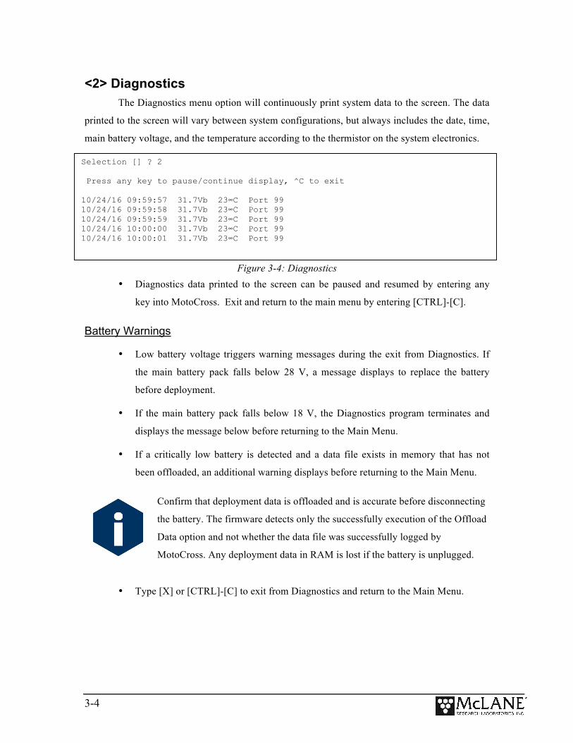
Instrument Settings <1> Set Time
The set time menu option allows you to program the system real time clock (RTC).
McLane recommends setting the RTC during the power-up sequence. When the PPS is powered
on, the clock defaults to January 1,1970, 00:00:00. The clock can be set to any date and time in
the allowed range and the count will continue from the new value.
Systems with a backup battery will retain the date and time as long as the backup
batteries are installed and have an acceptable voltage. Systems without a backup battery will not
keep time when the main battery pack is unplugged. To set the time:
1. Select the Set Time menu option.
2. Enter the date and time using the provided format.
3. Accept the changes to the system clock.
Clock reads 02/08/70 02:20:25. Change [N] ? y Format is mm/dd/[yyyy or yy] hh:mm:ss Enter correct time [02/08/1970 02:21:25] ? 03/04/2015 11:29:11 Clock reads 03/04/2015 11:29:11. Change [N] ? Initializing data array ..............................
Figure 3-3: Set Time
3-4
<2> Diagnostics The Diagnostics menu option will continuously print system data to the screen. The data
printed to the screen will vary between system configurations, but always includes the date, time,
main battery voltage, and the temperature according to the thermistor on the system electronics.
Figure 3-4: Diagnostics • Diagnostics data printed to the screen can be paused and resumed by entering any
key into MotoCross. Exit and return to the main menu by entering [CTRL]-[C].
Battery Warnings
• Low battery voltage triggers warning messages during the exit from Diagnostics. If
the main battery pack falls below 28 V, a message displays to replace the battery
before deployment.
• If the main battery pack falls below 18 V, the Diagnostics program terminates and
displays the message below before returning to the Main Menu.
• If a critically low battery is detected and a data file exists in memory that has not
been offloaded, an additional warning displays before returning to the Main Menu.
Confirm that deployment data is offloaded and is accurate before disconnecting
the battery. The firmware detects only the successfully execution of the Offload
Data option and not whether the data file was successfully logged by
MotoCross. Any deployment data in RAM is lost if the battery is unplugged.
• Type [X] or [CTRL]-[C] to exit from Diagnostics and return to the Main Menu.
Selection [] ? 2 Press any key to pause/continue display, ^C to exit 10/24/16 09:59:57 31.7Vb 23∞C Port 99 10/24/16 09:59:58 31.7Vb 23∞C Port 99 10/24/16 09:59:59 31.7Vb 23∞C Port 99 10/24/16 10:00:00 31.7Vb 23∞C Port 99 10/24/16 10:00:01 31.7Vb 23∞C Port 99

3-5
<3> Manual Operations The Manual Operations menu allows you to operate the different peripherals such as the
valve and pump installed on your PPS. The manual operations available in this menu will vary
depending on the system configuration.
• Manual Valve Operations: Options 1 – 4 of the PPS Manual Operation Menu move
the 25 Port Valve to the specified positions.
• Manual Pumping Operations: Options 5 – 7 of the PPS Manual Operation Menu
allows the user to perform manual pumping operations based on predefined, or user-
defined pumping parameters.
• Manual Fixative Valve Operation: If the PPS has a Fixative Valve installed, the
Manual Operation Menu will have an option that switches between the OFF (Water)
and ON (Fixative) positions.
Figure 3-5: Manual Operation Menu
Do not run the pump dry. If conducting a bench test, submerge the PPS intake
and exhaust lines in water.
________________________________________________________________ Configuration: WTS-125M-SV CF2 V2_05 of May 9 2016
_________________________________ Manual Operation
_________________________________ Mon Oct 24 10:00:04 2016
Port 99
<1> Find port : home <2> Find port : J <3> Next port : advance <4> Next port : retreat <5> Run pump : forward (250 ml @ 100 ml/min) <6> Run pump : reverse (250 ml @ 100 ml/min) <7> Run pump : programmable <8> Fixative Valve: OFF
<M> Main Menu
Selection [] ? 1

3-6
Option <1> Find Port: home
This option moves the valve to a reference position located at the water flush port, also
known as the Home Port or Port 0.
Figure 3-6: Find Port: Home
Option <2> Find Port:
This option moves the valve to a specified port.
Option <3> Next port:advance
This option moves the valve forward one port position (for example, from Home Port 00
to Port 01).
Figure 3-7: Next Port: Advance
Selection [] ? 1
Seeking home port.. located. Aligning... Confirmed.
Seeking port 01.. located. Aligning... Confirmed. ________________________________________________________________
Configuration: WTS-125M-SV CF2 V2_05 of May 9 2016
_________________________________ Manual Operation
_________________________________ Mon Oct 24 10:00:49 2016
Port 01
<1> Find port : home <2> Find port : J <3> Next port : advance <4> Next port : retreat <5> Run pump : forward (250 ml @ 100 ml/min) <6> Run pump : reverse (250 ml @ 100 ml/min) <7> Run pump : programmable <8> Fixative Valve: OFF
<M> Main Menu
Selection [] ?

3-7
Option <4> Next port:retreat
This option moves the valve backwards one port position (for example, from Port 01 to
Home Port 00).
Figure 3-8: Next Port: Retreat
Option <5> Run pump: forward
This option pumps 500 ml of water at 75 ml/min. in the forward direction. The pump can
be stopped at any time before the operation is complete by pressing [CTRL]-[C]. Each row of the
display shows the pump speed control value; the instantaneous pump speed in Hertz, the average
pump speed in Hertz, the cumulative volume pumped, the instantaneous flow rate in ml/min, and
the elapsed time in seconds.
Figure 3-9: Run Pump Forward
Selection [] ? 4
Seeking port 00.. located. Aligning... Confirmed.
Selection [] ? 5
Counts |Hall Freq |Hall Avg | Volume Pumped |FlowRate | Elapsed Seconds | Batt. V | Pump Current |Code 1920 h 179 I_Hz 44 A_Hz 1.2 ml 74.8 ml/min 1 secs 31.7 V 81 mA 0
1921 h 239 I_Hz 104 A_Hz 2.9 ml 99.9 ml/min 2 secs 31.7 V 71 mA 0
1901 h 249 I_Hz 166 A_Hz 4.6 m 104.1 ml/min 3 secs 31.7 V 78 mA 0 . . .
1921 h 238 I_Hz 238 A_Hz 246.3 ml 99.5 ml/min 148 secs 31.7 V 91 mA 0 1923 h 238 I_Hz 238 A_Hz 247.9 ml 99.5 ml/min 149 secs 31.7 V 87 mA 0 1919 h 241 I_Hz 239 A_Hz 249.6 ml 100.8 ml/min 150 secs 31.7 V 84 mA 0
Volume reached
Total volume pumped = 250 ml Elapsed time of event = 151 sec Lowest battery detected = 31.7 V
Average pump current = 83 mA Highest pump current = 96 mA
Display shortened to save space

3-8
Option <6> Run pump: reverse
This option pumps 500 ml of water at 75 ml/min. in the reverse direction. The pump can
be stopped at any time before the operation is complete by pressing [CTRL]-[C].
Figure 3-10: Run Pump Reverse
Option <7> Run pump: programmable
Use this option to enter the volume, time limit and direction for pumping. The pump can
be stopped at any time before the operation is complete by pressing [CTRL]-[C].
The various software features controlling and safeguarding pump operation are in effect
whenever the pump is running.
Selection [] ? 6
Counts | Hall Freq | Hall Avg | Volume Pumped | FlowRate | Elapsed Seconds | Batt. V | Pump Current | Code
1926 h 176 I_Hz 44 A_Hz 1.2 ml 73.6 ml/min 1 secs 31.7 V 88 mA 0 1939 h 233 I_Hz 102 A_Hz 2.9 ml 97.4 ml/min 2 secs 31.7 V 86 mA 0 1925 h 246 I_Hz 163 A_Hz 4.6 ml 102.9 ml/min 3 secs 31.7 V 82 mA 0 ... 1921 h 238 I_Hz 238 A_Hz 246.3 ml 99.5 ml/min 148 secs 31.7 V 91 mA 0 1923 h 238 I_Hz 238 A_Hz 247.9 ml 99.5 ml/min 149 secs 31.7 V 87 mA 0 1919 h 241 I_Hz 239 A_Hz 249.6 ml 100.8 ml/min 150 secs 31.7 V 84 mA 0
Volume reached
Total volume pumped = 250 ml Elapsed time of event = 151 sec Lowest battery detected = 31.7 V
Average pump current = 83 mA Highest pump current = 96 mA
Press any key to continue.
Display shortened to save space
3-9
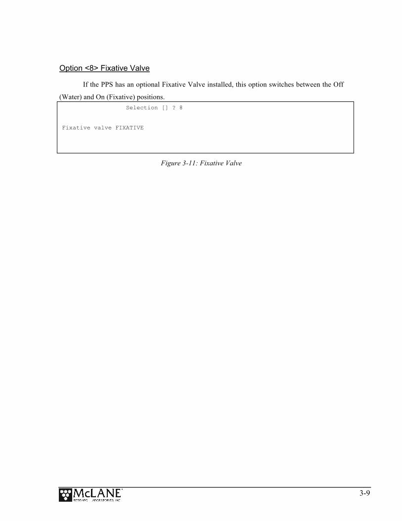
Option <8> Fixative Valve
If the PPS has an optional Fixative Valve installed, this option switches between the Off
(Water) and On (Fixative) positions.
Figure 3-11: Fixative Valve
Selection [] ? 8
Fixative valve FIXATIVE
3-10
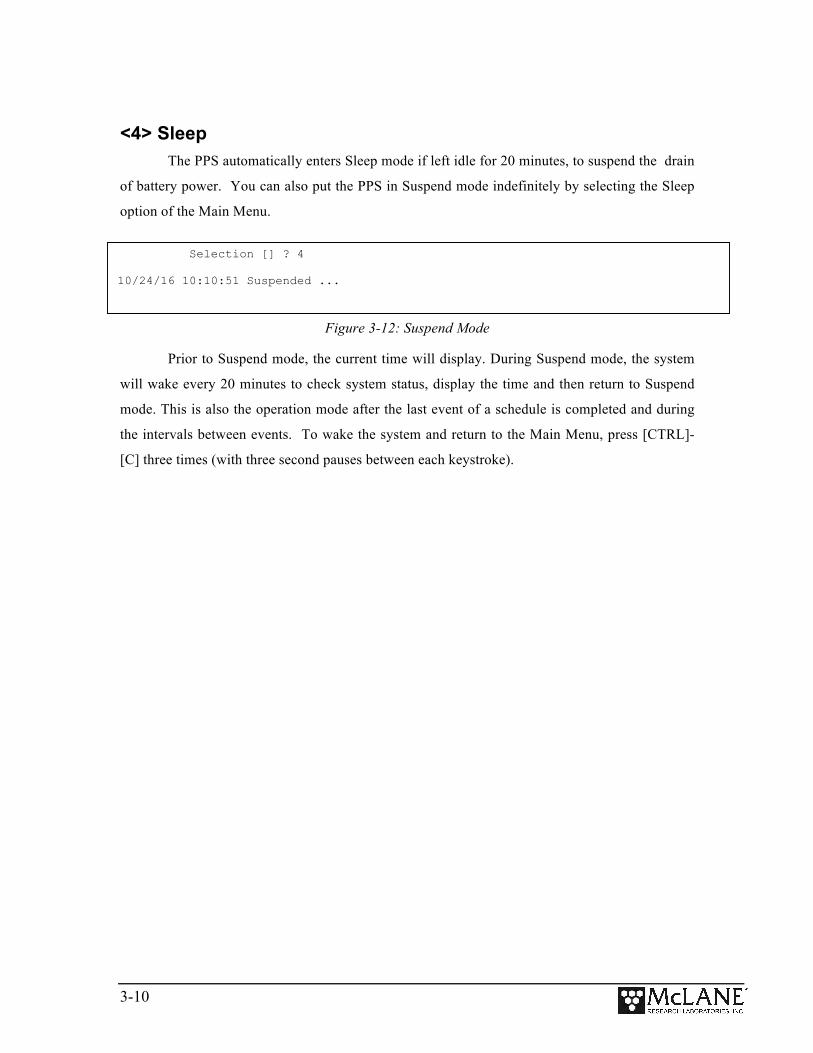
<4> Sleep The PPS automatically enters Sleep mode if left idle for 20 minutes, to suspend the drain
of battery power. You can also put the PPS in Suspend mode indefinitely by selecting the Sleep
option of the Main Menu.
Figure 3-12: Suspend Mode
Prior to Suspend mode, the current time will display. During Suspend mode, the system
will wake every 20 minutes to check system status, display the time and then return to Suspend
mode. This is also the operation mode after the last event of a schedule is completed and during
the intervals between events. To wake the system and return to the Main Menu, press [CTRL]-
[C] three times (with three second pauses between each keystroke).
Selection [] ? 4 10/24/16 10:10:51 Suspended ...

3-11
Section 3.3
Deployment Settings The remaining Main Menu options are used to prepare and perform a deployment. These
options are:
• Create Schedule: Used to create a sampling schedule before the actual deployment.
The schedule specifies the number of samples to be taken (from 1 through 25), and
consists of preprogrammed dates and times that will trigger pumping events.
• Deploy System: Checks EEPROM and requires a reboot if data is stored there,
confirms that the valve is aligned to Home Port (00), and warns if there is data ready
to be offloaded. Confirms the date and time, changes or keeps the existing sampling
schedule, and displays a final sampling parameter check with options to make
changes.
• Offload Data: Works with the “Capture to file” feature of MotoCross. After
recovering the PPS and re-connecting the communications cable to the electronics
and the computer, this option captures data to a text file.
Deployment Settings (create schedule, deploy system are explained in Chapter 4
‘Operations’ of this user manual. Offload Data options are explained in Chapter 5 of this
user manual.
3-12
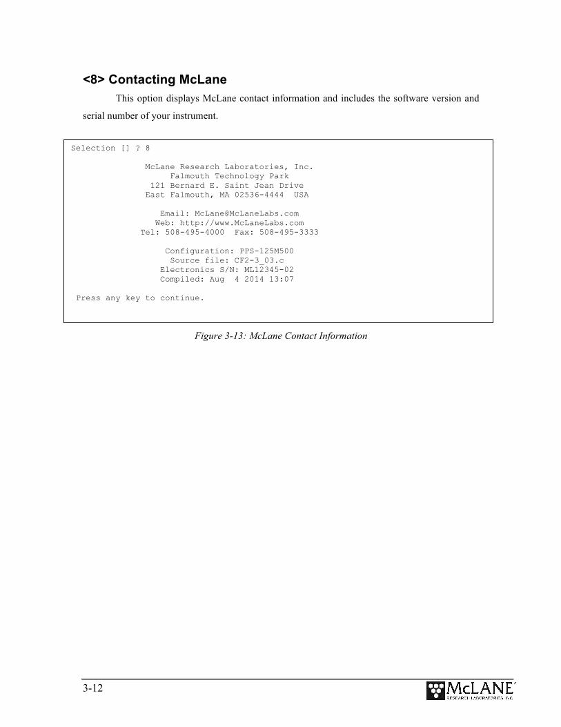
<8> Contacting McLane This option displays McLane contact information and includes the software version and
serial number of your instrument.
Figure 3-13: McLane Contact Information
Selection [] ? 8 McLane Research Laboratories, Inc. Falmouth Technology Park 121 Bernard E. Saint Jean Drive East Falmouth, MA 02536-4444 USA Email: [email protected] Web: http://www.McLaneLabs.com Tel: 508-495-4000 Fax: 508-495-3333 Configuration: PPS-125M500 Source file: CF2-3_03.c Electronics S/N: ML12345-02 Compiled: Aug 4 2014 13:07 Press any key to continue.

4-1
Chapter 4 Operations
This chapter describes the procedures involved in preparing the PPS for a deployment.
Topics include:
• Priming the PPS Filter Holders and Plumbing.
• Installing the Water Flush Filter
• Preparing the optional Fixative Valve for a Deployment.
• Preparing the optional Post-Sample Acid Flush Reservoir
• Programming deployment parameters.
Section 4.1Priming the PPS Filter Holders and Plumbing
The ultimate goal of the priming procedure is to clear all fluid lines and valve ports of
trapped air. This is a wet process and should be completed by two people.
Parts for the Priming Process Hose A
Hose B
Hose C
Hose D
Hose E
Hose F
Water Syringe
Fixative Syringe Optional if fixative valve is installed
To prime the PPS:
1. Follow the steps in the Getting Started chapter of this User Manual to establish
communications with the PPS.
2. Close and seal the controller housing.
3. From the Manual Operation Menu select option 1 to align the 25 port valve to the
home port.

4-2
4. Check option 8 of the Manual Operations Menu to make sure the Fixative valve
is OFF (the water position).
5. Locate the Water Syringe, Hose-A, Hose-B, and Hose-C in the toolkit.
6. Disconnect all of the filter bodies from the filter base plate, but keep the tops of
the filter bodies connected to the 25 port valve.
Figure 4.1-1:Priming Setup
7. Place a container of neutral water on top of the 25 port valve.
8. Connect Hose-A to the common intake on the 25 port valve (or to the Water
sample Reservoir intake if the Fixative is installed) and place the opposite end in
the water container.
9. Connect Hose-A to the common intake on the 25 port valve. If the fixative valve
is installed, connect Hose-A to the water intake port of the fixative valve instead.
Place the opposite end of Hose-A in the water container.
10. Connect Hose-C to the syringe, fill the syringe with water, and remove air from
the syringe.
11. Select option 3 of the Manual Operation Menu to advance to the next port (Port
1).

4-3
12. Open filter holder 1 by twisting the top half from the bottom half, and connect
the bottom half of the filter to Hose-C which is connected to the syringe.
Figure 4.1-2:Priming Setup
13. Use the syringe to inject water through the bottom half of the filter holder until
all air is removed and water pools on the top.
Figure 4.1-3: Injecting Water with Syringe
14. Place a filter on the bottom half of the filter holder, and allow it to soak up the
pool of water. Continue to slowly inject water if the filter requires more to
become completely saturated.

4-4
15. Reattach the bottom half to the top half of the filter body. The top filter ring of
the filter holder must be fully engaged and tightened down to the filter holder
body. To avoid introducing air back into the purged bottom half of the filter
body, the syringe can be used to inject water very slowly while attaching the top
and bottom halves.
Figure 4.1-4: Reattaching Top and Bottom of Filter
16. Once the two halves of the filter body are connected, slowly inject the remaining
contents of the syringe through the filter body to remove all air from the
remaining plumbing. Lightly tapping the filter against the PPS frame while
doing this will remove any trapped air. As water is injected, air bubbles should
appear in the water container.
17. Continue injecting until air bubbles stop, the syringe may need to be refilled
during this process.
The filter body has a valved connection and will seal immediately when
disconnected quickly. This seal will protect from introducing air while refilling
the syringe. Remember to remove all air from the syringe before reconnecting
the syringe to the filter body.
18. When all air has been purged from the filter position plumbing, disconnect the
syringe from the filter body.

4-5
19. Connect Hose-G to port 1 on the filter base plate, and place the other side of the
hose in the water container.
Figure 4.1-5: Reattaching Top and Bottom of Filter
20. Select option 6 of the Manual Operation Menu to pump 500 ml of water at 125
ml/minute in reverse [R]. While the system pumps in reverse, air is pushed from
the plumbing into the water container. Once all air has been removed from the
filter position plumbing, cancel the pumping operation with [CTRL]-[C].
Figure 4.1-6: Pump in Reverse
________________________________________________________________ Configuration: WTS-125M-SV CF2 V2_05 of May 9 2016 _________________________________ Manual Operation _________________________________ Mon Oct 24 10:04:13 2016 Port 00 <1> Find port : home <2> Find port : J <3> Next port : advance <4> Next port : retreat <5> Run pump : forward (250 ml @ 100 ml/min) <6> Run pump : reverse (500 ml @ 125 ml/min) <7> Run pump : programmable <8> Fixative Valve: OFF <M> Main Menu Selection [] ? 6 Counts | Hall Freq | Hall Avg | Volume Pumped | FlowRate | Elapsed Seconds | Batt. V| Pump Current |Code 1942 h 168 I_Hz 42 A_Hz 1.2 ml 70.2 ml/min 1 secs 31.7 V 86 mA 0 1949 h 236 I_Hz 101 A_Hz 2.8 ml 98.7 ml/min 2 secs 31.7 V 84 mA 0 . . . Display shortened to save space
4-6
While pumping air, bubbles can become trapped in the bends of the tubing
below the base plate. These air bubbles should be helped out of the tubing by
gently tilting the hose upward to let the bubble to travel through the tube.
21. Select option 3 of the Manual Operation Menu to advance to the next port.
22. Disconnect Hose-G and reattach the filter body to port 1 of the filter base plate.
23. Repeat steps 12 – 22 for all filter positions.
24. After priming port 24, select option 3 of the Manual Operation Menu one last
time to advance to the home port.
25. Once priming is complete, disconnect Hose-A and Hose-B from the Fixative
valve, remove the water container from the top of the 25 Port Valve and move on
to the next step, Installing the Water Flush Filter.
4-7
Section 4.2Installing the Water Flush Filter
The water flush filter installed in-line to Home Port (Port 0) accepts a 25mm filter with a
pore size from 5 to 10 microns. The filter protects the pump head from damage by large particles
when the water flush clears the fluid lines between samples. This is an optional feature. To install
the water flush filter, complete the following steps:
1. Place the pump exhaust tube in a bucket of neutral water.
2. Connect the large syringe filled with neutral water to the valve intake.
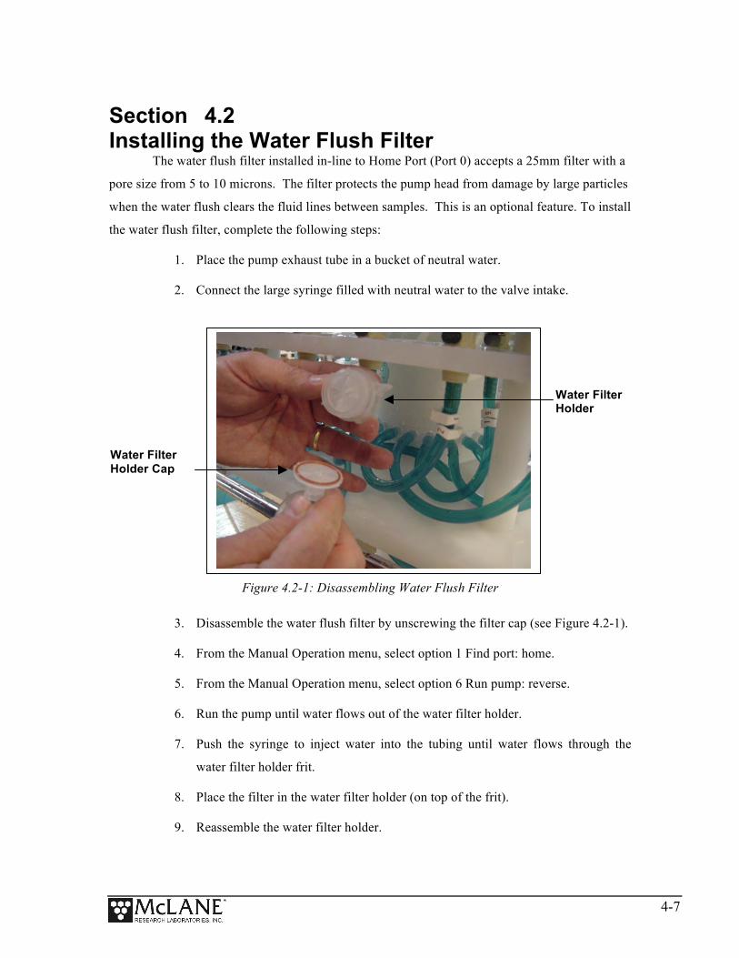
Figure 4.2-1: Disassembling Water Flush Filter
3. Disassemble the water flush filter by unscrewing the filter cap (see Figure 4.2-1).
4. From the Manual Operation menu, select option 1 Find port: home.
5. From the Manual Operation menu, select option 6 Run pump: reverse.
6. Run the pump until water flows out of the water filter holder.
7. Push the syringe to inject water into the tubing until water flows through the
water filter holder frit.
8. Place the filter in the water filter holder (on top of the frit).
9. Reassemble the water filter holder.
Water Filter Holder Cap
Water Filter Holder

4-8
Section 4.3Preparing the Fixative Valve for a Deployment
If the PPS has the optional Fixative valve, use the steps that follow to prime the Fixative
valve plumbing and prepare for a deployment. Skip section 4.3 and proceed to section 4.4 if you
do not have the Fixative option installed.
• Chemical Compatibility: PPS and Fixative materials are compatible with most
fixative solutions. Before deploying the PPS with the Fixative valve option, confirm
fixative concentrations by running tests to determine how much fixative is sufficient
for your specific science needs. Contact [email protected] for questions
about using specific fixatives.
PPS#System#Hydraulics#with#Fixa5ve#Valve#Op5on#
Fixa%ve(Valve(
Micropump(
24(Port(Valve(
Filter(Holder(
Fixa%ve(Bag(
Intake(from(Environment(
Collec%on(Bag(
Figure 4.3-1: PPS System Schematic with Fixative Valve Option
# # # ## # #
( (
(
( ( (
( (
( (
( ((
( (

4-9
Determining the Total Amount of Fixative
A few factors need to be considered when determining the total amount of fixative for a
deployment:
• The PPS with Fixative option includes 200 ml bags. Contact
[email protected] for information about using bags of a different size.
• A Fixative Flush of 4x the internal volume of the filter holder should be sufficient for
a fixative that requires a high end concentration.
• The internal volume of each PPS filter holder and tubing is approximately 22 ml.
• The maximum allowable fixative flush volume for a single event is 95% of the
available fixative volume divided by the number of events in the deployment.
Therefore:
Total Required Fixative = (Fixative Flush volume * number of events) + (1.05 * Fixative Reservoir Bag size)
While the provided fixative reservoir bag capacity is labeled as 2000 ml, it is
capable of holding approximately 2200 ml of fluid.
The deployment setup process requires an understanding of how much fixative is inside
of the Fixative Intake Bag prior to a deployment. The measurements on the Fixative Syringe can
be used to measure the amount of fixative added, although the purging process described in the
following steps can add or subtract from the injected amount. The most accurate way to measure
the fixative added to the fixative reservoir bag is to weigh the bags before, and after filling them.
Follow the recommended chemical safety precautions for the Fixative being
used.
4-10
Prime the Fixative Plumbing These instructions assume that the filter holder plumbing has already been primed, and
the 25 port valve has been aligned to the home port per the final instructions of the Filter Holder
Priming procedure in section 4.1. If these steps have not been completed, go back and follow
them before continuing.
1. Locate Hose E, Hose-A, and the Fixative Syringe.
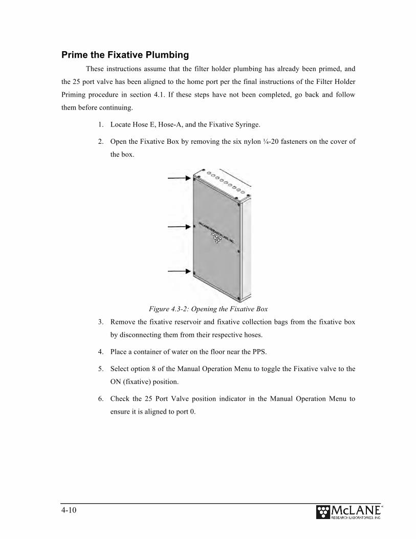
2. Open the Fixative Box by removing the six nylon ¼-20 fasteners on the cover of
the box.
Figure 4.3-2: Opening the Fixative Box
3. Remove the fixative reservoir and fixative collection bags from the fixative box
by disconnecting them from their respective hoses.
4. Place a container of water on the floor near the PPS.
5. Select option 8 of the Manual Operation Menu to toggle the Fixative valve to the
ON (fixative) position.
6. Check the 25 Port Valve position indicator in the Manual Operation Menu to
ensure it is aligned to port 0.

4-11
7. Connect Hose-A to the Fixative Collection-1 Hose inside of the Fixative Box,
and place the other end in the water container. Use the nut attached to the hose
as a weight to keep it submerged in the water container.
8. Connect Hose-E to the Fixative Syringe, and fill the syringe with Fixative.
9. Connect the Fixative Syringe and Hose-E to Fixative Reservoir-2 Hose inside the
Fixative Box.
10. Use the Fixative Syringe to SLOWLY inject fixative through the fixative
plumbing. This will cause air to exit Hose-A into the water container. If it is not
very easy to push water through the fixative plumbing, stop and check the
Manual Operation Menu to make sure that the Fixative is in the ON position, and
the 25 Port Valve is aligned to port 0.
Figure 4.3-3: Aligned to Home Port, Fixative ON
________________________________________________________________ Configuration: WTS-125M-SV CF2 V2_05 of May 9 2016
_________________________________ Manual Operation
_________________________________ Mon Oct 24 10:00:33 2016
Port 00
<1> Find port : home <2> Find port : J <3> Next port : advance <4> Next port : retreat <5> Run pump : forward (250 ml @ 100 ml/min) <6> Run pump : reverse (250 ml @ 100 ml/min) <7> Run pump : programmable <8> Fixative Valve: ON
<M> Main Menu

4-12
11. When the air bubbles have stopped, select option 8 of the Manual Operation
Menu to switch the Fixative valve to the OFF (Water) position. This will seal the
fixative plumbing, and keep air out.
12. Disconnect Hose-A, and the Fixative Syringe from the fixative intake and
exhaust plumbing.
Fill the Fixative Intake Bag 1. Weigh the Fixative Intake Bag, and make a note of the weight.
2. Locate the Fixative Syringe, Hose-F, and the quick disconnect plugs in the
toolkit.
3. Fill a container with fixative, place it on a surface with the fixative bags.
4. Connect the Fixative Syringe to Hose-F, and fill the syringe with fixative.

4-13
5. Inject the contents of the syringe into Fixative Intake Bag. Repeat this process
until the amount of fixative required by the deployment is added to the Fixative
Intake Bag.
Figure 4.3-4: Inject Syringe Contents into Fixative Bag
6. When filling is complete, remove Hose-F from the syringe, while leaving Hose-F
attached to the Fixative Intake Bag.
7. Place the free end of Hose-F into the fixative container using the nut attached to
the hose as a weight to keep the hose submerged.
Figure 4.3-5: Place Hose-F into Fixative Container
8. Squeeze the air out of the fixative intake bag, through the hose, into the
container.

4-14
Note that removing air from the bag will cause a slight vacuum, allowing the
bag to pull more fixative from the container after air is removed.
9. After air is removed, seal the Fixative Intake Bag by folding the end of the hose
and pinching it shut. Disconnect Hose-F from the Fixative Intake Bag, and
connect the quick disconnect plug.
Figure 4.3-6: Pinch Fixative Bag Hose, Attach to Intake-2 Hose
10. Weigh the Fixative Intake Bag and make a note of the weight. Subtract the filled
bag weight from the empty bag weight to determine the total amount of fixative
added.
11. Pinch the Fixative Intake Bag hose, disconnect the plug, while continuing to
pinch the hose, attach the bag to the Fixative Intake-2 hose inside of the Fixative
Box. If done correctly no air should have been introduced.
Fill the Fixative Collection Bag It is important to fill the collection bag with a volume of water equal to 5% of the bag’s
rated capacity. Without this water a differential pressure could build across Fixative valve O-ring
seals at ocean depths, potentially damaging the fixative valve.
1. Locate the Fixative Syringe, Hose-E, a water container, and the quick disconnect
plugs in the toolkit.
2. Connect Hose-E to the Fixative Syringe.

4-15
3. Fill the syringe with neutral water. This is the exhaust bag, and shouldn’t require
fixative.
4. Inject approximately 5% of the Fixative Exhaust Bag’s capacity into the bag.
5. When filling is complete, remove Hose-E from the syringe while leaving it
attached to the Fixative Exhaust bag.
6. Place the free end of Hose-E into the container using the nut attached to the hose
as a weight to keep the hose submerged.
7. Roll up the Fixative Exhaust Bag to force air from it into the water container.
Figure 4.3-7: Roll Fixative Bag to Release Air
8. Pinch the end of the Fixative Exhaust Bag hose, disconnect Hose-E. While
continuing to pinch the hose, attach the bag to the Fixative Exhaust-1 hose inside
of the Fixative Box. If done correctly no air should have been introduced.
9. Attach the Fixative Intake Bag and Fixative Exhaust Bag to the fixative box
using the nylon ¼ -20 fasteners. Keep the hose connections facing downward,
and the Fixative Exhaust bag in front of the Fixative Intake bag.

4-16
Section 4.4
Preparing the Post Sample Acid Flush Reservoir Acid provides an optional, programmable post-sample bio-fouling flush that further
cleans the intake tube. Port 24 is used as the antifouling acid flush chamber, leaving a maximum
of 23 sample events. Use the steps that follow to prepare the acid flush reservoir. Skip to section
4.5 if you are not using this optional feature.
Setting the acid flush and antifouling fluid volume is completed on the
Configuration menu. The Antifouling flush must also be enabled on the Event
Parameters menu. Individual event settings can be changed from the Schedule
Verification display. Contact [email protected] to upgrade an older PPS
system to use the post-sample acid flush feature (the addition of an acid
chamber is required).
1. Using option 3 from the Manual Operation menu, advance to Port 24, the
position used for acid cleaning.
2. Remove insert an acid bag in the fixative chamber.
3. Gently fold the bag, slide it into the chamber and secure the cap.
4. Install the supplied acid bag fitting.
5. Fill a clean syringe with an acid solution and inject acid into the bag. The acid
bag will hold just over 500 ml of acid, so filling will require multiple injections
from the syringe. Keep track of the volume of acid injected. Overfilling could
cause the bag to burst.
6. Remove the acid bag fitting and reconnect the top tubing.
7. Remove the clean water syringe from the valve intake and replace the intake cap.
8. From the Manual Operation menu, select option 6 Run pump: reverse. Perform a
reverse pump to fill the remaining volume of the acid reservoir with clean water.
9. Filling the entire volume may require a few restarts of the pumping routine.

4-17
10. Press [CTRL]-[C] to stop the pump manually when water emerges from the bleed
hole at the top of the acid cap.
11. Remove the intake cap and attach a syringe of acid solution.
12. Disconnect the top tubing from the acid cap and inject acid into the intake until
the top tubing is filled.
13. Reattach the top tubing to the acid reservoir cap.
14. Remove the acid syringe from the intake and replace the intake cap.
4-18
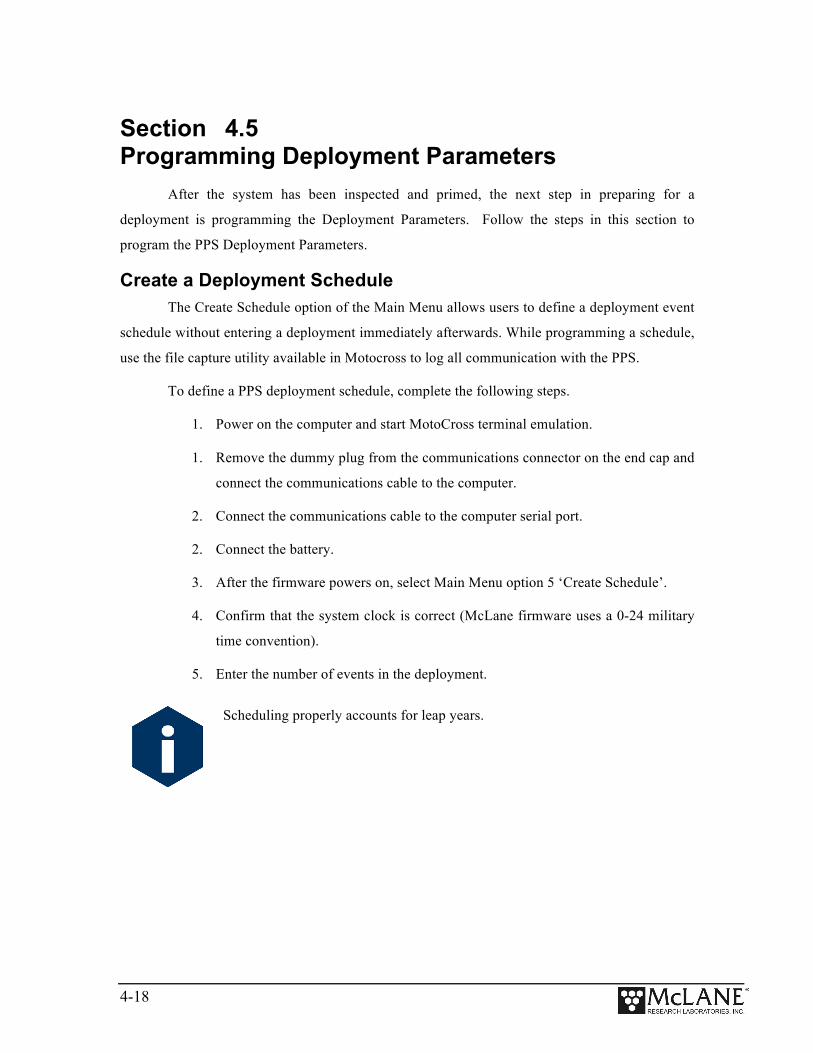
Section 4.5
Programming Deployment Parameters After the system has been inspected and primed, the next step in preparing for a
deployment is programming the Deployment Parameters. Follow the steps in this section to
program the PPS Deployment Parameters.
Create a Deployment Schedule The Create Schedule option of the Main Menu allows users to define a deployment event
schedule without entering a deployment immediately afterwards. While programming a schedule,
use the file capture utility available in Motocross to log all communication with the PPS.
To define a PPS deployment schedule, complete the following steps.
1. Power on the computer and start MotoCross terminal emulation.
1. Remove the dummy plug from the communications connector on the end cap and
connect the communications cable to the computer.
2. Connect the communications cable to the computer serial port.
2. Connect the battery.
3. After the firmware powers on, select Main Menu option 5 ‘Create Schedule’.
4. Confirm that the system clock is correct (McLane firmware uses a 0-24 military
time convention).
5. Enter the number of events in the deployment.
Scheduling properly accounts for leap years.

4-19
This prompt will be preceded by warnings if previous deployment records (a data
file) or a deployment schedule exist. The system requires a reboot to clear EEPROM
before saving a new schedule if there is at least one file in memory. If a reboot is
needed, a message displays.
Figure 4.5-1: System Reboot Required
Selection [] ? 5 Records show that the system requires a post-deployment reboot before proceeding with deployment setup. A data set exists in system memory that has not been offloaded. Existing data will be lost if the system is rebooted. Reboot now? [Y] ? y Resetting...
4-20
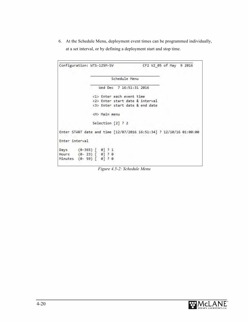
6. At the Schedule Menu, deployment event times can be programmed individually,
at a set interval, or by defining a deployment start and stop time.
Figure 4.5-2: Schedule Menu

4-21
Option <1> Enter each event time
This option enters events one at a time (month, day, year, hour, minute, and second). The
events do not have to be entered in chronological order and will be automatically sorted.
Option <2> Enter start date & interval
This option enters a start date and a desired interval between the event start times. The
interval is entered in units of days, hours and minutes.
Figure 4.5-3: Schedule – Option 2
Selection [2] ? 2 Enter START date and time [03/18/2015 10:25:45] ? 03 18 15 10 45 00 Enter interval Days (0-365) [ 0] ? Hours (0- 23) [ 0] ? Minutes (0- 59) [ 0] ? 20 Schedule Verification Event 1 of 48 at 03/18/15 10:45:00 Event 2 of 48 at 03/18/15 11:05:00 Event 3 of 48 at 03/18/15 11:25:00 Event 4 of 48 at 03/18/15 11:45:00 . . . Event 47 of 48 at 03/19/15 02:05:00 Event 48 of 48 at 03/19/15 02:25:00 Modify an event [N] ?
Display shortened to save space

4-22
Option <3> Enter start date & end date
This option schedules events at regular intervals between the entered start and end dates.
Figure 4.5-4: Schedule – Option 3
7. Review to confirm correct dates and times (press any key to scroll the display
forward).
Figure 4.5-5: Schedule Verification
8. Type Y to change an event date or time.
Selection [2] ? 3
Enter START date and time [03/17/2015 13:15:14] ? 03/17/2015 13:21:00 Enter END date and time [03/17/2015 13:15:31] ? 03/18/2015 07:48:00
Schedule Verification
Event 1 of 48 at 03/17/15 13:21:00 Event 2 of 48 at 03/17/15 13:44:33 Event 3 of 48 at 03/17/15 14:08:06 Event 4 of 48 at 03/17/15 14:31:39 . . . Event 47 of 48 at 03/18/15 07:24:18 Event 48 of 48 at 03/18/15 07:47:51
Modify an event [N] ?
Schedule Verification Event 1 of 48 at 03/17/15 13:21:00 Event 2 of 48 at 03/17/15 13:44:33 Event 3 of 48 at 03/17/15 14:08:06 Event 4 of 48 at 03/17/15 14:31:39… . . . Event 47 of 48 at 03/18/15 07:24:18 Event 48 of 48 at 03/18/15 07:47:51 Modify an event [N] ?
Display shortened to save space

4-23
Event Parameters Menu
After a schedule is defined, the user is brought to the Event Parameters Menu. The
parameters defined here will be applied globally to all events in the deployment.
Figure 4.5-6: Event Parameters Menu
• Headers: Options A, B, and C of the Event Parameters Menu allow the user to define
three headers to describe the deployment.
• Water Flush: To prevent sample contamination and reduce accumulated bio-fouling, the
Home Port (Port 0) can be used to flush standing water from the 25 port valve intake tube
and valve heads before each sample is collected. Users can program the flush volume
here. The flush flow rate will always be the maximum flow rate the pump is capable of,
and the time limit is automatically calculated by the system.
__________________________________________________ Event Parameters __________________________________________________ Header A| B| C| Water D| Flushing volume = 100 [ml] Flush | Flushing time limit = 2 [min] Sample E| Sample volume = 20000 [ml] F| Pumping flow rate = 200 [ml/min] G| Minimum flow rate = 75 [ml/min] H| Pumping time limit = 267 [min] Fixative J| Enabled Flush K| Fixative volume = 25 [ml] L| Pumping flow rate = 150 [ml/min] M| Minimum flow rate = 100 [ml/min] N| Pumping time limit = 1 [min] Antifouling O| Enabled Flush P| Antifouling volume = 20 [ml] Q| Pumping flow rate = 150 [ml/min] R| Minimum flow rate = 100 [ml/min] S| Pumping time limit = 1 [min] Data I| Pump data period = 1 [min] V| Verify and continue.

4-24
• Sample: Sample volume, flow rate, minimum flow rate, and pumping time limits are
user-programmable, and acceptable values are determined by the system configuration.
• Data: Pump data is stored to memory at a set interval while pumping a sample. This
interval is user-programmable, and applied to all deployment events.
• Fixative Flush: If the PPS is configured with the optional Fixative valve, the Fixative
Flush must be enabled in the Event Parameters Menu. The Fixative Flush is disabled by
default, after enabling the Fixative Flush using menu option J, program the available
fixative volume. Once these initial steps are completed, global Fixative Flush parameters
are defined in the Event Parameters menu. However, specific parameters can also be
created for each event.
• Post-Sample Antifouling Flush (optional): The PPS can perform an acid flush after
sample events if the optional anti foul chamber option is installed. This option uses Port
24 as an antifouling flush chamber, leaving a maximum of 23 sample events. The anti-
fouling flush can be changed for individual samples later in the deployment setup.

4-25
Optional Post-Sample Antifouling Flush
This option is enabled on the Configuration menu. The maximum recommended anti-
fouling flush volume for a sample event is the total available volume less 10 divided by the
number of events in the deployment.
Figure 4.5-7: Configuration Menu
Contact [email protected] to upgrade an older PPS to the antifoul flush
option.
________________________________________________________________
Configuration: WTS-250M-SV CF2 V2_05 of Apr 8 2016 _________________________________
Configuration _________________________________
Fri Apr 8 13:32:57 2016
<1> 50ml pump: No <2> 125ml pump: No <3> 250ml pump: Yes <M> Maxon motor: Yes <P> Pittman motor: No <S> Fixative valve: Yes
Volume: 1000.0 ml <A> Antifouling fluid: Yes
<X> Save & Exit <^C> Cancel & Exit
Selection [] ? a
Is there an Antifouling fluid installed? [N] ? y Enter the available antifouling fluid volume (ml) (0.0 to 500.0) [500.0] ? 500

4-26
Schedule Verification and Modifying Individual Event Parameters
Once the global event parameters are defined and accepted, the next step is the schedule
verification.
• All events and their individual parameters are printed to the screen, and the system asks if
the user wants to modify any events.
• At this point users can modify individual event parameters by answering ‘Y’, and
specifying which event to modify.
In the example below the user modified the Fixative Flush volume and flow rate of Event 1.
Notice in the schedule verification that Event 1 will now only pump a 50 ml fixative flush at 100
ml/min. If no event parameters need modifying, respond ‘N’ to this question. All data will be
saved, and the PPS will return to the Main Menu.
Figure 4.5-8: Event 1 Parameters

4-27
Figure 4.5-9: Schedule Verification
Checking for Event Overlap
After a schedule is accepted, the PPS firmware checks for potential problems, such as
expired or overlapping events.
If an overlap occurs during deployment, the start of the next event is delayed until the
current event is completed (an overlap condition does not terminate the deployment).
Event overlap is calculated after the sampling parameters have been entered and is based
on the acid exposure delay and the duration of the combined flushing and sample volumes at their
minimum flow rates. The system compares the time limit of each event to the scheduled start
time of each subsequent event.
The warning message indicates that an overlap could occur, not that it will.
Entering a schedule with intentionally short intervals can be a technique to
secure rapid, sequential samples. The overlap message is only a reminder and
can be ignored if tight scheduling is intended.

4-28
The following event(s) overlap previous event(s): 2 3 4 5 The listed events may begin later than their scheduled start. Any events that are actually delayed will start as soon as earlier events are completed. Press any key to continue.
Figure 4.5-10: Overlap Reminder
One line of system status information displays followed by a message reminder to offload
data written to the EEPROM backup during a previous deployment. Disregard the message if the
data has already been recovered.
The pre-deployment process checks to confirm that backup batteries are
correctly installed. If backup batteries are not detected, the firmware will not
accept the ‘Y’ entry to start the deployment.
The data offload reminder and low power sleep check will be followed by a prompt to
proceed with or terminate the deployment (a final chance to check the settings prior to
deployment). The deployment will not start if the low power sleep test fails.

4-29
Figure 4.5-11: Deploy System
If the main battery voltage is too low to support the deployment, warnings will display.
Proceeding with the Deployment
After the status line (and battery warnings if any), a final prompt displays. Type Y to
commit to the deployment (or N to cancel and return to the Main Menu). Prior to submerging the
sampler, disconnect the communications cable from the controller housing. Reconnect the
dummy plug to the communications connector on the controller housing and deploy the PPS.
Figure 4.5-12: Proceed with Deployment
Proceed with the deployment [N] ? y Erasing EEPROM entries ......................... >>> Remove communication cable and attach dummy plug. <<< >>> System is ready to deploy. <<< 03/17/15 13:18:38 Waiting for event 01 of 48 @ 03/17/15 13:21:00 03/17/15 13:18:38 Suspended until 03/17/15 13:21:00 ...
Performing 6 second low-power sleep mode test... System status: 05/02/16 15:40:08 35.9Vb 27∞C Port 00 Caution: Deployment will erase all EEPROM data backup entries. Proceed with the deployment Yes|No [N] ?

4-30
The PPS enters a low power sleep mode until the time of the first scheduled event. The
PPS automatically wakes up and begins sampling at the scheduled time of the first pumping
event.
>>> Remove communication cable and attach dummy plug. <<<
>>> System is ready to deploy. <<<
03/06/15 10:38:46 Waiting for event 01 of 05 @ 03/06/15 11:30:00
03/06/15 10:38:46 Suspended until 03/06/15 11:30:00 ....
Figure 4.5-13: Deploy System For a bench test, leave the communications cable attached to the PPS electronics to
observe the operation of the instrument in the MotoCross window.
Pumping begins whether or not the PPS is on station. Reconnecting the COM
cable and typing [CTRL]-[C] will terminate the deployment.

5-1
Chapter 5 Deployment and Recovery Attaching to a Mooring
The PPS can be deployed on different mooring types. Once sampling is complete, the
recovery process includes removing the filters and offloading deployment data.
Deployment Preparation After the Operations steps are completed, deploying the PPS requires the following (in
order):
• Connect the battery and close the end cap (see chapter 2 for details about the end cap and connectors).
• Connect the communicaitons cable and confirm firmware deployment settings (see chapter 4 for details about programming the deployment).
• Disconnect the communiucations cable and attach the dummy plug. • Attach the PPS to the mooring.
Recovery Procedure After the deployment is completed, the required steps are:
• Remove the water from the top of the filters.
• Remove the filters for storage and later analysis.
• Offload the deployment data.
Steps for offloading the data are included in this User Manual.
Emptying Water and Removing the Filters
This procedure clears the water above the filters in the filter holders.
Do not open the filter holders until these steps are completed and water is
removed from above the filters.
1. Remove the filter holder in tact.
2. Connect the syringe and the 1/8” ID tubing (provided in the toolkit) with the
male quick disconnect fitting to the bottom of the filter holder.
5-2
3. Using the syringe, create a vacuum on the filter holder to draw the water through
the filter. Continue until water is no longer flowing into the syringe.
4. Open the filter holder, carefully remove the filter and store it for analysis.
5. Repeat steps 1-4 for each filter holder.
6. Perform necessary maintenance on the PPS after all filter holders are removed.
Offloading Data Once the steps are completed to recover the PPS, data can be offloaded. This section
contains instructions for running the data offload. The deployment data will display on screen and
a log file can be created for use in analysis.
This procedure can be repeated because deployment data remains in memory until a new
deployment schedule is created or the batteries are drained and/or removed.
Do not disconnect the battery (which erases the data) until checking the capture
files to confirm that the data offload was successful.
1. Start Motocross on the host computer (see Chapter 2 in this User Manual for
Terminal emulation details).
2. Within MotoCross, specify a “Capture file” for the offloaded data.
3. If necessary, turn the capture On.

5-3
4. Connect the communications cable to a computer and then connect the
communications cable to the PPS.
The computer should be on and MotoCross running before connecting to the
PPS electronics.
5. From the Offload/Display Data File Menu select option <1>, <2>, <3>, or <4> to
display recorded data.
Figure 5-1: Offload/Display Data File Menu
The screens that follow show Option <1> ‘Display ALL Data’.
6. Press any key to offload the data and display to the screen (the data is saved to
the Capture filename specified in Step 2). An example data offload file is shown
next.
________________________________________________________________ Configuration: WTS-125M-SV CF2 V2_05 of May 9 2016 _________________________________ Offload/Display Data File _________________________________ Mon Oct 24 13:04:49 2016 <1> Display ALL data <2> Display event summary data <3> Display pump data <4> EEPROM data backup cache <M> Main Menu Selection [] ? 1

5-4
Figure 5-2: Display All Data
________________________________________________________________ Configuration: WTS-125M-SV CF2 V2_05 of May 9 2016 _________________________________ Offload/Display Data File _________________________________ Mon Oct 24 13:04:49 2016 <1> Display ALL data <2> Display event summary data <3> Display pump data <4> EEPROM data backup cache <M> Main Menu Selection [] ? 1 Start the capture file now. Then, press any key to start the transfer. The data file will remain in memory and is not erased by this offload procedure. Software version: WTS-2.05.c Compiled: May 9 2016 14:09:28 Electronics S/N: ML12345-03 Data start: 10/24/16 10:57:20 Data stop: 10/24/16 13:04:37
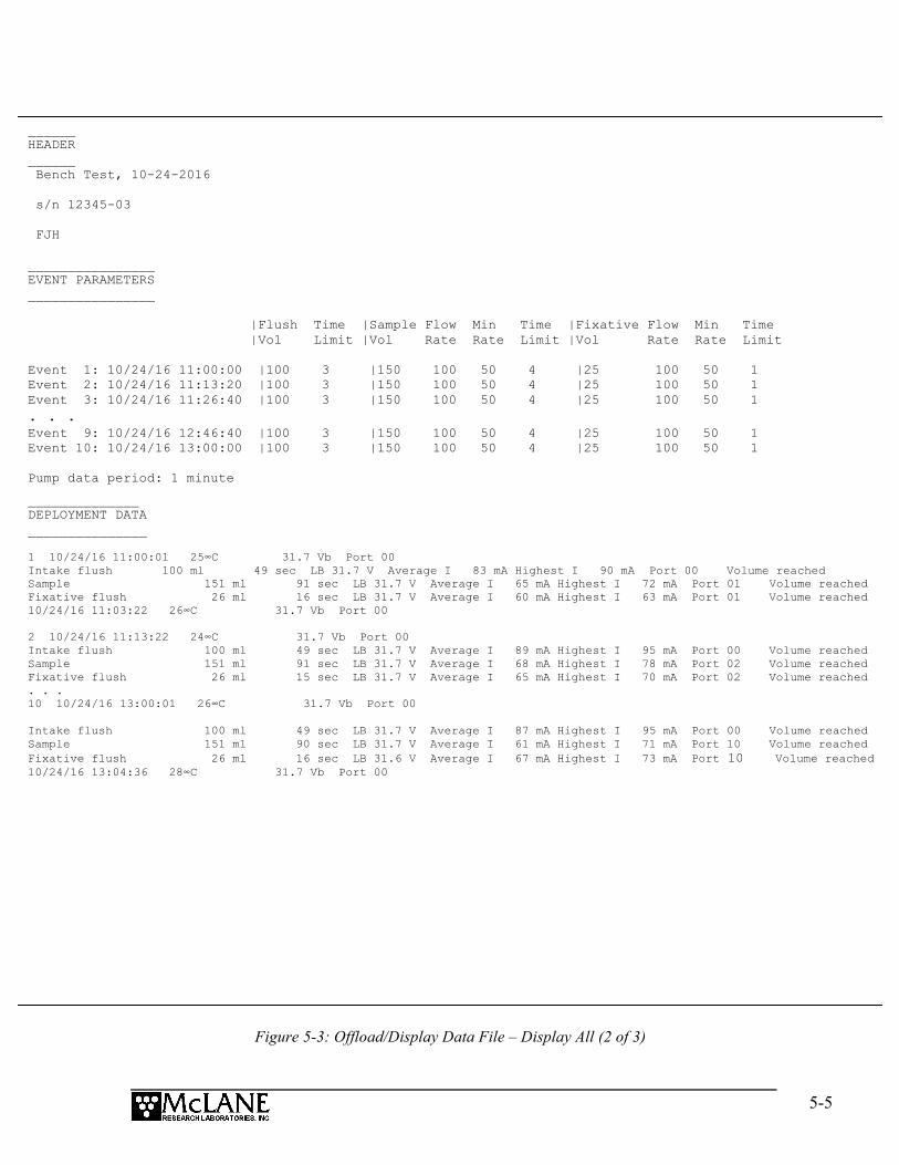
5-5
Figure 5-3: Offload/Display Data File – Display All (2 of 3)
______ HEADER ______ Bench Test, 10-24-2016 s/n 12345-03 FJH ________________ EVENT PARAMETERS ________________ |Flush Time |Sample Flow Min Time |Fixative Flow Min Time |Vol Limit |Vol Rate Rate Limit |Vol Rate Rate Limit Event 1: 10/24/16 11:00:00 |100 3 |150 100 50 4 |25 100 50 1 Event 2: 10/24/16 11:13:20 |100 3 |150 100 50 4 |25 100 50 1 Event 3: 10/24/16 11:26:40 |100 3 |150 100 50 4 |25 100 50 1 . . . Event 9: 10/24/16 12:46:40 |100 3 |150 100 50 4 |25 100 50 1 Event 10: 10/24/16 13:00:00 |100 3 |150 100 50 4 |25 100 50 1 Pump data period: 1 minute
______________ DEPLOYMENT DATA _______________ 1 10/24/16 11:00:01 25∞C 31.7 Vb Port 00 Intake flush 100 ml 49 sec LB 31.7 V Average I 83 mA Highest I 90 mA Port 00 Volume reached Sample 151 ml 91 sec LB 31.7 V Average I 65 mA Highest I 72 mA Port 01 Volume reached Fixative flush 26 ml 16 sec LB 31.7 V Average I 60 mA Highest I 63 mA Port 01 Volume reached 10/24/16 11:03:22 26∞C 31.7 Vb Port 00 2 10/24/16 11:13:22 24∞C 31.7 Vb Port 00 Intake flush 100 ml 49 sec LB 31.7 V Average I 89 mA Highest I 95 mA Port 00 Volume reached Sample 151 ml 91 sec LB 31.7 V Average I 68 mA Highest I 78 mA Port 02 Volume reached Fixative flush 26 ml 15 sec LB 31.7 V Average I 65 mA Highest I 70 mA Port 02 Volume reached . . . 10 10/24/16 13:00:01 26∞C 31.7 Vb Port 00 Intake flush 100 ml 49 sec LB 31.7 V Average I 87 mA Highest I 95 mA Port 00 Volume reached Sample 151 ml 90 sec LB 31.7 V Average I 61 mA Highest I 71 mA Port 10 Volume reached Fixative flush 26 ml 16 sec LB 31.6 V Average I 67 mA Highest I 73 mA Port 10 Volume reached 10/24/16 13:04:36 28∞C 31.7 Vb Port 00

5-6
Figure 5-4: Offload/Display Data File – Display All (3 of 3)
7. After the data is offloaded, stop the Motocross file capture.
The Offload option can be repeated if necessary (the data file remains in
memory until a new deployment schedule is created or the batteries are
disconnected).
8. From the Main Menu, select <4> Sleep to put the firmware into Suspend mode.
9. Disconnect the COM cable from the controller and reinstall the dummy plug.
___________ PUMPING DATA ____________
Pump data period = 1 minute
[event#] [ml/min] [ml] [Vbat] [Av. Cur] [High Cur]
1 100 100 31.7 65.0 72.0 2 100 100 31.7 68.0 78.0
3 100 100 31.7 67.0 75.0 4 100 100 31.7 65.0 73.0 5 100 100 31.7 63.0 71.0
6 100 100 31.7 67.0 74.0 7 100 100 31.7 70.0 78.0 8 100 100 31.7 65.0 71.0 9 100 100 31.7 66.0 72.0
10 100 100 31.7 62.0 71.0
End of instrument data file.
Terminate file logging operation now and press any key to continue.
6-1
Chapter 6 Maintenance and Storage
Several maintenance procedures before and after each deployment provide smooth
operation and long instrument life for the PPS. Rinsing the entire instrument assembly with clean
fresh water after every deployment is critical to prevent corrosion. Other maintenance
recommendations are included in this chapter.
Cleaning the PPS Fluid Paths and Filter Holders Allowing the buildup of biofouling and salt is detrimental to system performance and will
shorten the life of the PPS. Follow the steps in this section to clean the fluid pathways of the PPS
after every deployment.
The recommended cleaning solution is a 1:10 hydrochloric acid water mixture.
Preparing To Clean:
1. Follow the steps in Chapter 2 ‘Getting Started with your McLane Sampler” to establish
communications with the PPS.
2. Enter the Manual Operation Menu and select option 1 to align the 25 Port Valve to the
home port.
3. Check option 8 of the Manual Operations Menu to make sure the optional Fixative
Valve is OFF (the water sample position).
4. Prepare 3 liters of cleaning solution, a container to collect system exhaust, and 9 liters
of reverse osmosis or distilled water in separate containers.
5. Find Hose-A, Hose-B, Hose-F, the water container, and the Water Syringe in the PPS
toolkit.
6. Fill the container with cleaning solution and place it on top of the 25 port valve.
7. Remove the water flush filter holder (if used).
8. Connect Hose-A to the Water Intake port of the Fixative valve.
6-2
9. Connect Hose-B to the Water Exhaust port of the Fixative valve, and place the opposite
end in the exhaust container.
10. Attach Hose-F to the Water syringe, and fill the syringe with water.
11. Attach the opposite end of Hose-F to Hose-A, and SLOWLY inject water through the
pump to prime the pump plumbing.
Pump Cleaning Solution Each Port:
1. Select option 3 of the Manual Operation Menu to advance to port 1.
2. Remove the syringe and Hose-F from Hose-A, and place Hose-A in cleaning solution.
3. Select option 7 of the Manual Operation Menu to pump 100 ml of cleaning solution
forward at the 125 ml/minute.
4. When this pumping operation completes, advance to the next port to seal the cleaning
solution in the port plumbing.
5. Repeat this process for ports 2-24.
Rinse Each Port:
6. Remove Hose-A from the cleaning solution and place it in a container of neutral water.
7. Select option 7 of the Manual Operation Menu to pump 300 ml of water forward at the
125 ml/minute through port 1.
8. Repeat this process for all ports.
9. After all ports have been cleaned, return to port 0.
Cleaning the Optional Fixative Plumbing 1. Disconnect the Fixative Intake and Fixative Exhaust from their respective bags.
2. Connect Hose-A to the Fixative Intake Hose in the Fixative Box, and place the other end
of Hose-A in the cleaning solution.
3. Connect Hose-B to the Fixative Exhaust Hose in the Fixative Box, and place the other
end of Hose-B into the exhaust container.
4. Select option 8 of the Manual Operation Menu to switch the Fixative Valve to the ON
position.

6-3
5. Select option 7 of the Manual Operation Menu to pump 100 ml of cleaning solution
forward at the 125 ml/minute.
6. To seal the cleaning solution in the fixative plumbing select option 8 of the Manual
Operation Menu to switch the Fixative Valve to the OFF position.
7. Place Hose-A in neutral water, and let the cleaning solution soak for about 10 minutes.
8. After the cleaning solution has soaked for 10 minutes in the fixative plumbing, select
option 8 of the Manual Operation Menu to switch the Fixative Valve to the ON position.
9. Select option 7 of the Manual Operation Menu to pump 300 ml of water forward at the
125 ml/min through the fixative plumbing.
10. To seal the cleaning solution in the fixative plumbing select option 8 of the Manual
Operation Menu to switch the Fixative Valve to the OFF position.
Final Flush
1. Connect Hose-A to the Water sample Intake port of the Fixative Valve and the other end
in the water container.
2. Connect Hose-B to the Water sample Exhaust port of the Fixative Valve, and place the
opposite end in the exhaust container
3. Select option 7 of the Manual Operation Menu to pump 300 ml of water forward at 125
ml/minute through port 0.
Clean and Inspect Filter Holders
After the lines have been cleaned and rinsed, open the filter holders and clean the threads
and O-rings with alcohol and a lint-free wipe. Inspect the O-rings visually and feel them for wear.

6-4
Pump Gears Periodically examine the graphite pump gears and replace them if there are any visible
signs of wear or cracks. To inspect the gears, complete the following steps:
1. Remove the pump from the PPS and remove the four screws that hold the pump
head to the pump housing.
2. Carefully remove the pump head from the pump housing (the gears are mounted
on the bottom of the pump head). Invert the pump housing for easier removal.
Figure 6-1: Pump Housing, Gears, and Pump Head Magnet
Do not remove the magnet cavity from the pump motor housing (the area under
the metal cavity is filled with oil).
Magnet Cavity
Pump Gears
Pump Head Magnet
Pump Housing

6-5
Storage The shipping crate is a reusable international freight container that is ISPM-15 compliant
for international transport.
To prevent instrument damage during transport or storage, crate should remain
upright. Avoid excessive vibration and extreme temperatures for prolonged
periods of time.
There are several procedures to complete before packing the PPS in the crate for storage
longer than one month:
• Offload all data from memory.
• Rinse all instrument components with fresh water.
• Flush the valve with fresh water.
• Always disconnect and remove batteries. For a battery pack that is still usable,
first cover the connector with insulation tape and then store the battery in a
refrigerator.
• Reassemble the main battery holder and insert the electronics package back into
the controller housing.
• Replace all bolts and apply a small amount of anti-seize to the threads.

6-6
Notes

Appendix A-1
Appendix A Adaptive Sampling Firmware
Adaptive sampling firmware provides the user with command-line control over the PPS.
By issuing commands from a provided command set, the user has full control over the system and
can execute valve movements, pumping operations, and other system functions.
The Adaptive Sampling option requires a continuous RS-232 connection from
the PPS to a computer or other microcontroller.
PPS Adaptive Sampling firmware AWT-2_05 and higher includes Antifouling and
Solenoid Valve commands, and an Adaptive Deployment option. Adaptive deployment automates
many of the necessary steps required to perform a deployment from the command-line interface.
• The Antifouling option replaces Sample 24 with an antifouling reservoir bag and
sample container.
• The Fixative Valve option is used to administer a fixative onto the sample filter
after the water sample has been taken. See the User Manual for more detailed
information.
Adaptive Deployment An Adaptive Deployment is a deployment that is pre-programmed to perform the same
functions as a standard (time-series) deployment, except that a serial command sent to the
controller triggers each sample collection. In standard deployment mode, a date and time trigger
sample collection.
Adaptive deployment provides a single command that automates many deployment steps,
or users can perform on-demand actions by using commands that function the same as the
Manual Operations menu in the standard PPS firmware.
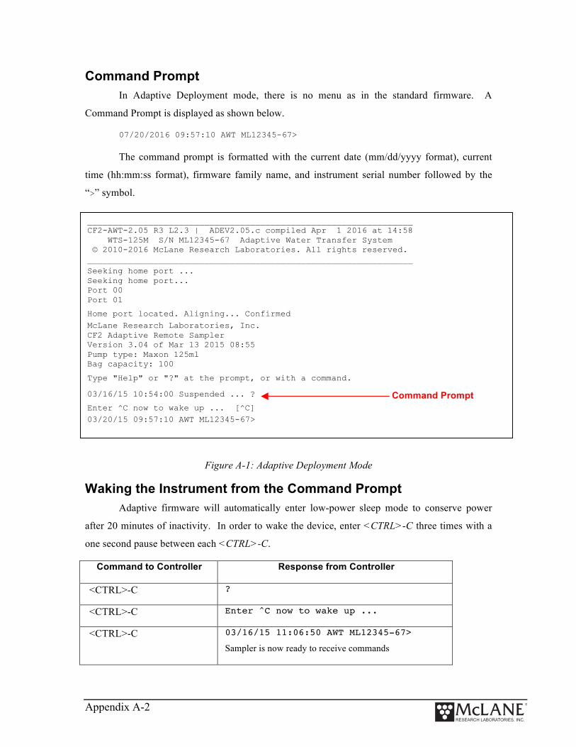
Appendix A-2
Command Prompt In Adaptive Deployment mode, there is no menu as in the standard firmware. A
Command Prompt is displayed as shown below.
07/20/2016 09:57:10 AWT ML12345-67>
The command prompt is formatted with the current date (mm/dd/yyyy format), current
time (hh:mm:ss format), firmware family name, and instrument serial number followed by the
“>” symbol.
Figure A-1: Adaptive Deployment Mode
Waking the Instrument from the Command Prompt Adaptive firmware will automatically enter low-power sleep mode to conserve power
after 20 minutes of inactivity. In order to wake the device, enter <CTRL>-C three times with a
one second pause between each <CTRL>-C.
Command to Controller Response from Controller
<CTRL>-C ?
<CTRL>-C Enter ^C now to wake up ...
<CTRL>-C 03/16/15 11:06:50 AWT ML12345-67>
Sampler is now ready to receive commands
________________________________________________________________ CF2-AWT-2.05 R3 L2.3 | ADEV2.05.c compiled Apr 1 2016 at 14:58 WTS-125M S/N ML12345-67 Adaptive Water Transfer System © 2010-2016 McLane Research Laboratories. All rights reserved. ________________________________________________________________
Seeking home port ... Seeking home port... Port 00 Port 01
Home port located. Aligning... Confirmed
McLane Research Laboratories, Inc. CF2 Adaptive Remote Sampler Version 3.04 of Mar 13 2015 08:55 Pump type: Maxon 125ml Bag capacity: 100
Type "Help" or "?" at the prompt, or with a command.
03/16/15 10:54:00 Suspended ... ?
Enter ^C now to wake up ... [^C]
03/20/15 09:57:10 AWT ML12345-67>
Command Prompt

Appendix A-3
AWT Commands (Adaptive PPS Sampling) The section that follows lists AWT commands included in firmware AWT-2_05 and
higher. Some parameters are password protected to prevent accidental configuration changes.
Where passwords are required, the entry is mclane. Commands are listed in alphabetical order.
Command Help Command help is displayed by entering “Help” at the command line, or by entering a
question mark after a specific command (Figure A-2).
Figure A-2: Command Help
Command: ANTIFOUL Syntax: ANTIFOUL | ENABLE or DISABLE Description: Enables or disables antifoul operations. Example: 03/20/15 09:57:10 AWT ML12345-67>ANTIFOUL ENABLE 03/20/15 09:57:10 AWT ML12345-67>ANTIFOUL DISABLE
Command: ANTIFOULFLUSHSyntax: ANTIFOULFLUSH | volume | flow rate | min. flow rate | time limit Description: Performs an Antifouling Flush using the specified parameters. Example: 03/20/15 09:57:10 AWT ML12345-67>ANTIFOULFLUSH 20 80 50 0
07/15/16 10:19:21 AWT ML12345-67>applyfixative ? _____________
APPLYFIXATIVE _____________
____________ Description: ____________
Apply fixative using the provided parameters.
Example: APPLYFIXATIVE 10 100 50 0 1 _______ Syntax: _______
APPLYFIXATIVE |volume|flow rate|min. flow|time limit|port
Type command ? for Help
Command description
Command example
Command syntax
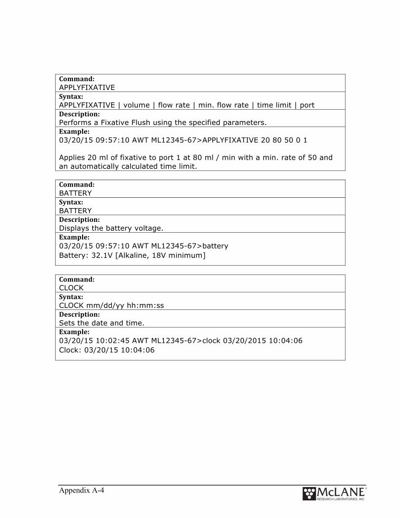
Appendix A-4
Command: APPLYFIXATIVE Syntax: APPLYFIXATIVE | volume | flow rate | min. flow rate | time limit | port Description: Performs a Fixative Flush using the specified parameters. Example: 03/20/15 09:57:10 AWT ML12345-67>APPLYFIXATIVE 20 80 50 0 1 Applies 20 ml of fixative to port 1 at 80 ml / min with a min. rate of 50 and an automatically calculated time limit. Command: BATTERY Syntax: BATTERY Description: Displays the battery voltage. Example: 03/20/15 09:57:10 AWT ML12345-67>battery Battery: 32.1V [Alkaline, 18V minimum]
Command: CLOCK Syntax: CLOCK mm/dd/yy hh:mm:ss Description: Sets the date and time. Example: 03/20/15 10:02:45 AWT ML12345-67>clock 03/20/2015 10:04:06 Clock: 03/20/15 10:04:06

Appendix A-5
Command: CODES Syntax: CODES Description: Displays the pumping termination code table. Pumping codes are displayed in the RESULT command.
Example: 03/20/15 10:04:06 AWT ML12345-67>codes
Termination Codes: # description 0 = Pumping in progress 1 = Volume reached 2 = Time limit reached 3 = Min flow reached 4 = Low battery 5 = Stopped by user 6 = Pump would not start
Command: COPYRIGHT Syntax: COPYRIGHT Description: Displays the firmware copyright notice. Example: 03/20/15 10:04:06 AWT ML12345-67>copyright
_____________________________________________________________ CF2-AWT-2.05 R3 L2.3 | ADEV2.05.c compiled Apr 1 2016 at 14:58 WTS-125M S/N ML12345-67 Adaptive Water Transfer System © 2010-2016 McLane Research Laboratories. All rights reserved. _____________________________________________________________ Command: DATE Syntax: DATE mm/dd/yy Description: Sets the date. Example: 03/20/15 10:46:20 AWT ML12345-67>date 03/20/15 Clock: 03/20/15 10:47:04

Appendix A-6
Command: EXIT password required Syntax: EXIT [password] Description: Exits the program to the operating system. Restart the program by typing app at the prompt. Example: 03/20/15 10:47:04 AWT ML12345-67>exit mclane Command: FORWARD Syntax: FORWARD volume | flow rate | min. flow rate | time limit Description: Starts a forward pump operation. If zero is entered for time limit, time limit will automatically be calculated based on the volume and the minimum allowable flow rate. Example: 03/20/15 10:41:10 AWT ML12345-67>forward 50 100 50 0 | --- command --- | ------------------------- result -------------------------- | port vol flo min tl vol flowr minfl sec mmddyy hhmmss batt V pump cur. code Status 00 | 50 100 50 2 | 1.1 69.0 0.0 1 040116 111220 | 29.8 V 91 mA 0 Status 00 | 50 100 50 2 | 2.7 92.0 0.0 2 040116 111221 | 29.8 V 87 mA 0 Status 00 | 50 100 50 2 | 4.3 99.9 0.0 3 040116 111222 | 29.8 V 80 mA 0 Status 00 | 50 100 50 2 | 6.0 100.3 0.0 4 040116 111223 | 29.8 V 90 mA 0 Status 00 | 50 100 50 2 | 7.7 100.3 0.0 5 040116 111224 | 29.8 V 88 mA 0 Status 00 | 50 100 50 2 | 9.4 99.9 0.0 6 040116 111225 | 29.8 V 89 mA 0 Status 00 | 50 100 50 2 | 11.0 99.9 0.0 7 040116 111226 | 29.8 V 85 mA 0 Status 00 | 50 100 50 2 | 12.7 100.3 0.0 8 040116 111227 | 29.8 V 88 mA 0

Appendix A-7
Command: HELP Syntax: [command] ? Description: Displays the help text including syntax. Example: 07/15/16 10:19:21 AWT ML12345-67>applyfixative ? _____________ APPLYFIXATIVE _____________ ____________ Description: ____________ Apply fixative using the provided parameters. Example: APPLYFIXATIVE 10 100 50 0 1 _______ Syntax: _______ APPLYFIXATIVE |volume|flow rate|min. flow|time limit|port Command: HISTORY Syntax: HISTORY Description: Displays the command history list. Example: 07/15/16 10:19:21 AWT ML12345-67>HISTORY -1: COPYRIGHT -2: VERSION -3: SERIAL -4: CODES -5: CLOCK 11/11/11 11:11:11 -6: DATE 11/11/11 -7: TIME 11:11:11 -8: TIME -9: BATTERY -10: ID -11: REVERSE 50 100 50 0 -12: PUMPTYPE mclane maxon 125 -13: PUMPTYPE

Appendix A-8
Command: HOME Syntax: HOME Description: Sets the valve to the home position Example: 07/15/16 10:19:21 AWT ML12345-67>HOME Seeking port 24... Located. Aligning... Confirmed.
Seeking home port... Located. Aligning... Confirmed.
Port: 00 Command: ID Syntax: ID Description: Displays identification information. Example: 07/15/16 10:19:21 AWT ML12345-67>ID Identity: CF2-ADEV2.05 ML12345-67 Command: MCLANE Syntax: MCLANE Description: Displays McLane contact information.

Appendix A-9
Command: OFFLOAD Syntax: OFFLOAD ALL Description: Offloads deployment data. Example: 03/20/15 10:41:10 AWT ML12345-67> OFFLOAD ALL Command: OFFLOADEEP Syntax: OFFLOADEEP Description: Offloads EEPROM deployment data Example: Example: 03/20/15 10:41:10 AWT ML12345-67> OFFLOADEEP ____________ EVENT SUMMARY _____________ Event: 1 Start time: 04/01/16 11:26:34 Volume pumped: 101 ml Elapsed time: 61 sec Lowest battery: 29.8 V Average current: 87.0 mA Highest current: 93.0 mA Port used: 00 Stop time: 04/01/16 11:29:41 Status: Volume reached End of EEPROM event backup cache. Terminate file logging operation now and press any key to continue. End of EEPROM data. Command: PAUSEDEPLOY Syntax: PAUSEDEPLOY Description: Pauses an adaptive deployment. This command is built in because certain commands cannot be executed while there is an active deployment. It is not suggested to enter these commands mid-deployment, but this command makes it possible.

Appendix A-10
Command: PORT Syntax: PORT [port] Description: Displays or sets the valve position. Example: 03/20/15 10:51:20 AWT ML12345-67>port 1 Command: PRINTPARMS Syntax: PRINTPARAMS Description: Print the programmed event parameters. Example: 03/20/15 10:51:20 AWT ML12345-67>PRINTPARAMS SAMPLE PARAMETERS _________________ 04/01/16 11:12:55 Water Flush: Volume [ml] = 100 Flow rate [ml/min] = 100 Min. flow rate [ml/min] = 50 Time limit [minutes] = 3 Sample: Volume [ml] = 101 Flow rate [ml/min] = 101 Min. flow rate [ml/min] = 51 Time limit [minutes] = 3 Fixative Flush: Volume [ml] = 25 Flow rate [ml/min] = 70 Min. flow rate [ml/min] = 50 Time limit [minutes] = 1

Appendix A-11
Command: PUMPTYPE password required Syntax: Set pump type: PUMPTYPE | password | Maxon or Pittman | 125 or 250 Display pump type: PUMPTYPE
Description: Displays or sets the pump type. Example: 03/20/15 10:52:39 AWT ML12345-67>pumptype mclane maxon 250 Configuration successfully stored Pump type: Maxon 250ml Command: QUIT password required Syntax: QUIT [password] Description: Quits the program. Example: 03/20/15 10:52:39 AWT ML12345-67>quit mclane Command: REBOOT Syntax: REBOOT Description: Reboots system, after confirming the command. Example: 03/20/15 10:52:39 AWT ML12345-67>REBOOT Reboot the system? [N] ? Command: REBOOTNOW Syntax: REBOOTNOW Description: Reboots system immediately.
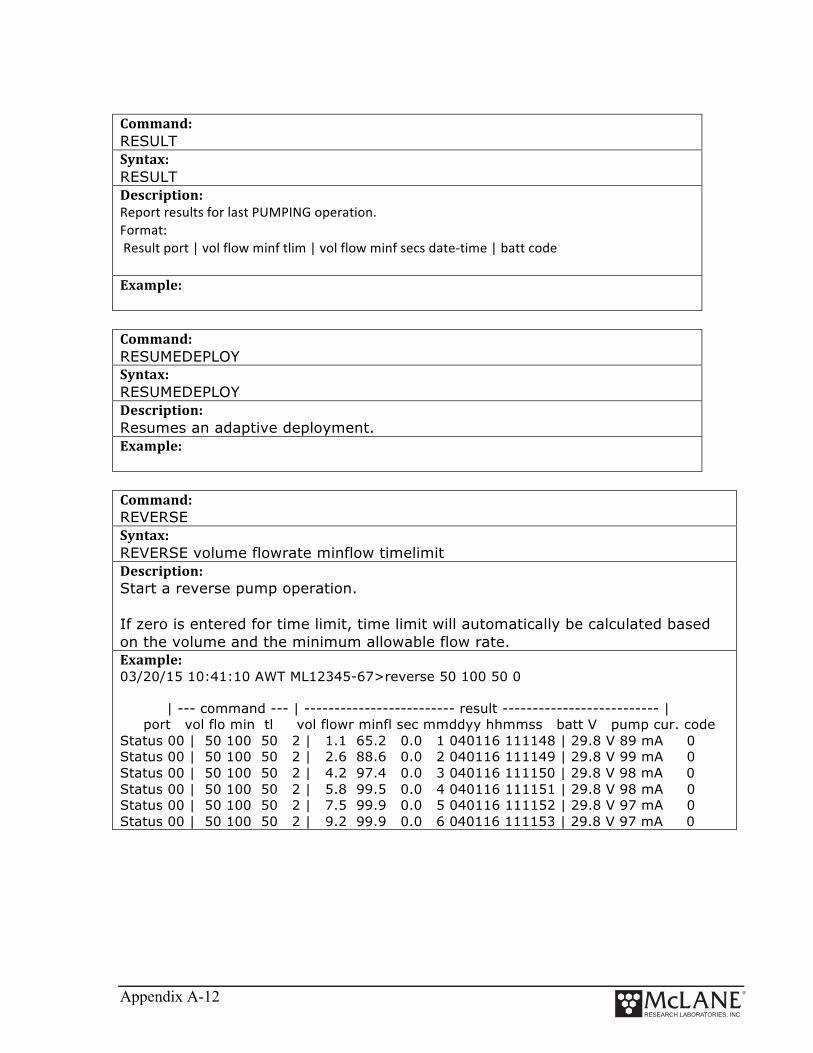
Appendix A-12
Command: RESULT Syntax: RESULT Description: Report results for last PUMPING operation. Format: Result port | vol flow minf tlim | vol flow minf secs date-‐time | batt code Example: Command: RESUMEDEPLOY Syntax: RESUMEDEPLOY Description: Resumes an adaptive deployment. Example: Command: REVERSE Syntax: REVERSE volume flowrate minflow timelimit Description: Start a reverse pump operation. If zero is entered for time limit, time limit will automatically be calculated based on the volume and the minimum allowable flow rate. Example: 03/20/15 10:41:10 AWT ML12345-67>reverse 50 100 50 0 | --- command --- | ------------------------- result -------------------------- | port vol flo min tl vol flowr minfl sec mmddyy hhmmss batt V pump cur. code Status 00 | 50 100 50 2 | 1.1 65.2 0.0 1 040116 111148 | 29.8 V 89 mA 0 Status 00 | 50 100 50 2 | 2.6 88.6 0.0 2 040116 111149 | 29.8 V 99 mA 0 Status 00 | 50 100 50 2 | 4.2 97.4 0.0 3 040116 111150 | 29.8 V 98 mA 0 Status 00 | 50 100 50 2 | 5.8 99.5 0.0 4 040116 111151 | 29.8 V 98 mA 0 Status 00 | 50 100 50 2 | 7.5 99.9 0.0 5 040116 111152 | 29.8 V 97 mA 0 Status 00 | 50 100 50 2 | 9.2 99.9 0.0 6 040116 111153 | 29.8 V 97 mA 0

Appendix A-13
Command: SAMPLE Syntax: SAMPLE Description: Sample next position in an adaptive deployment using the predefined parameters programmed with the set command. The system must be in an active deployment. Example: See Figure E-3 in this Appendix Command: SAMPLERESULT Syntax: SAMPLERESULT Description: Displays results of last sample. Example: 03/20/15 10:41:10 AWT ML12345-67>SAMPLERESULT 1 Start: 04/01/16 11:26:34 29.8 Vbat 25.2 ¯C PORT = 00 Intake Flush PORT 00 100 ml 61 sec LB 29.8 V Average I 83.0 mA Highest I 89.0 mA Volume reached Sample PORT 01 101 ml 61 sec LB 29.8 V Average I 87.0 mA Highest I 93.0 mA Volume reached Fixative Flush PORT 01 25 ml 22 sec LB 29.8 V Average I 57.0 mA Highest I 64.0 mA Volume reached End: 04/01/16 11:29:42 29.8 Vbat 26.0 ¯C PORT = 00 Command: SERIAL Syntax: SERIAL Description: Displays the sampler serial number. Example: Serial: ML12345-67

Appendix A-14
Command: SET Syntax: SET | procedure name | Procedure parameters (see examples) Description: Sets event parameters for an adaptive deployment. Example: Auto calculate time limits by entering zero for time limit value. Example: SET WATER 100 200 50 0
To turn flush off just enter: SET WATER 0
PRE-SAMPLE FLUSH PARAMETERS: SET | WATER | VOLUME | FLOW RATE | MINIMUM FLOW RATE | TIME LIMIT (Minutes) Example: SET WATER 100 200 50 0
SAMPLE PARAMETERS: SET | SAMPLE | VOLUME | FLOW RATE | MINIMUM FLOW RATE | TIME LIMIT (Minutes) Example: SET SAMPLE 500 200 50 0
FIXATIVE PARAMETERS (if solenoid valve is installed and enabled): SET | FIXATIVE | VOLUME | FLOW RATE | MINIMUM FLOW RATE | TIME LIMIT (Minutes) Example: SET FIXATIVE 30 75 50 0
ANTIFOULING FLUSH PARAMETERS (If antifouling is installed and enabled): SET | ANTIFOUL | VOLUME | FLOW RATE | MINIMUM FLOW RATE | TIME LIMIT (Minutes) Example: 03/20/15 10:41:10 AWT ML12345-67> SET ANTIFOUL 30 75 50 0
Command: SLEEP Syntax: SLEEP Description: Invokes low-power sleep.

Appendix A-15
Command: STARTDEPLOY Syntax: STARTDEPLOY Description: Starts an adaptive deployment. Allows user to perform samples using parameters defined with the SET command. The system automatically selects the next port in the deployment and will stop when there are no available ports left to sample. Example: See Figure E-8 in this Appendix. Command: STOPDEPLOY Syntax: STOPDEPLOY Description: Stops an adaptive deployment. Command: SV Syntax: SV | ENABLE or DISABLE SV | ON or OFF SV | FIXATIVE or OCEAN Description: The SV command has arguments that will enable or disable the solenoid valve, and switch the solenoid valve position. ON is the alternate fluid source (typically a fixative) and off is the resting position, which is plumbed to the primary fluid source (the environment) you can use either the ON/OFF arguments or the OCEAN/FIXATIVE arguments to switch the valve position. Example: 03/20/15 10:41:10 AWT ML12345-67>SV ENABLE - Configures system with a solenoid valve. 03/20/15 10:41:10 AWT ML12345-67>SV DISABLE - Configures system without a solenoid valve. 03/20/15 10:41:10 AWT ML12345-67>SV ON - Energizes solenoid valve, switches to alternate fluid position. 03/20/15 10:41:10 AWT ML12345-67>SV FIXATIVE Energizes solenoid valve, switches to alternate fluid position.. 03/20/15 10:41:10 AWT ML12345-67>SV OFF - De-energizes solenoid valve, moves to resting position (default fluid position). 03/20/15 10:41:10 AWT ML12345-67>SV OCEAN - De-energizes solenoid valve, moves to resting position (default fluid position).

Appendix A-16
Command: TIME Syntax: TIME hh:mm:ss Description: Sets the time. Example: 03/20/15 10:41:10 AWT ML12345-67>TIME 11:11:11 Clock: 04/01/16 11:11:11 Command: VERSION Syntax: VERSION Description: Displays version information Example: 03/20/15 10:41:10 AWT ML12345-67>VERSION Version: McLane Research Laboratories, Inc. CF2 Adaptive Water Transfer System Version 2.05 of Apr 1 2016 14:58 Pump type: Maxon 125ml Command: VOLUME Syntax: VOLUME | ANTIFOUL or FIXATIVE Description: Sets the available fixative or antifouling fluid volume. Example: 03/20/15 10:41:10 AWT ML12345-67>VOLUME FIXATIVE 100 03/20/15 10:41:10 AWT ML12345-67>VOLUME ANTIFOULING 100

Appendix A-17
Using Automated Adaptive Commands To perform an adaptive deployment, use the SET, STARTDEPLOY and SAMPLE
commands. Use the OFFLOAD DATA command to offload the deployment data.
SET Command With the SET command, the user can predefine water flush, sample parameters, fixative
flush, and antifouling flush parameters.
Figure A-3: SET Command
Deploy Commands The commands STARTDEPLOY and ENDEPLOY start and stop the automated
deployment. After the sample event parameters have been predefined, entering STARTDEPLOY
starts the deployment. The system clears stored data from the previous deployment, then goes to
sleep until the user enters the SAMPLE command to wake the system.
Figure A-4: STARTDEPLOY Command Sample Command
When the SAMPLE command is entered the system automatically selects the next
available port, executes the predefined sample parameters, and records event data. The system
locates the next port, confirms alignment and remains in suspend mode until the next sample is
automatically triggered (Figure A-5).
The SET command can be run during the deployment to change the sample volume, flow
rates and time limits, for the remaining samples.
03/13/15 10:54:03 AWT ML12345-67>startdeploy Erasing previous deployment data ............. Deployment started. 04/01/16 11:12:58 Suspended ... 04/01/16 11:20:01 Suspended ... SAMPLE 04/01/16 11:26:34 Event 1 starting
03/13/15 10:43:48 AWT ML12345-67>set water 100 100 50 0
Water Flush: Volume [ml] = 100 Flow rate [ml/min] = 100 Min. flow rate [ml/min] = 50 Time limit [minutes] = 3

Appendix A-18
Figure A-5: SAMPLE and SET Commands
Collect Sample
Set Sample Parameters
Collect Sample
12/10/15 16:14:58 AWT ML12935-01>sample 12/10/15 16:15:01 Event 1 starting ____________________ FLUSHING INTAKE PORT ____________________ | --- command --- | ------------------------- result -------------------------- | port vol flo min tl vol flowr minfl sec mmddyy hhmmss batt V pump cur. code Status 00 | 50 125 100 1 | 0.6 36.4 0.0 1 121015 161503 | 22.5 V 105 mA 0 Status 00 | 50 125 100 1 | 2.0 81.1 0.0 2 121015 161504 | 22.5 V 129 mA 0 . . . Status 00 | 50 125 100 1 | 47.1 125.0 125.0 24 121015 161526 | 22.5 V 151 mA 0 Status 00 | 50 125 100 1 | 49.2 125.0 125.0 25 121015 161527 | 22.5 V 140 mA 0 Volume reached Total volume pumped = 50 ml Elapsed time of event = 26 sec Lowest battery detected = 22.5 V Average pump current = 142 mA Highest pump current = 151 mA Seeking port 01... Located. Aligning... Confirmed. ______________ PUMPING SAMPLE ______________ | --- command --- | ------------------------- result -------------------------- | port vol flo min tl vol flowr minfl sec mmddyy hhmmss batt V pump cur. code Status 01 | 255 125 50 6 | 0.6 36.4 0.0 1 121015 161540 | 22.5 V 108 mA 0 Status 01 | 255 125 50 6 | 2.0 81.5 0.0 2 121015 161541 | 22.5 V 133 mA 0 . . . Status 01 | 255 125 50 6 | 251.4 125.0 124.6 122 121015 161741 | 22.5 V 150 mA 0 Status 01 | 255 125 50 6 | 253.5 125.0 124.6 123 121015 161742 | 22.5 V 147 mA 0 Volume reached Total volume pumped = 255 ml Elapsed time of event = 124 sec Lowest battery detected = 22.5 V Average pump current = 149 mA Highest pump current = 153 mA Seeking port 02... Located. Aligning... Confirmed. 12/10/15 16:18:48 AWT ML12935-01>set sample 200 75 50 0 Sample: Volume [ml] = 200 Flow rate [ml/min] = 75 Min. flow rate [ml/min] = 50 Time limit [minutes] = 5 12/10/15 16:19:01 AWT ML12935-01>sample 12/10/15 16:19:04 Event 2 starting ____________________ FLUSHING INTAKE PORT ____________________ | --- command --- | ------------------------- result -------------------------- | port vol flo min tl vol flowr minfl sec mmddyy hhmmss batt V pump cur. code Status 00 | 100 75 50 3 | 0.6 36.8 0.0 1 121015 161906 | 22.5 V 75 mA 0 Status 00 | 100 75 50 3 | 1.6 57.3 0.0 2 121015 161907 | 22.5 V 84 mA 0 Shortened to save space
Shortened to save space
Shortened to save space

Appendix A-19
Ending the Deployment
The deployment automatically ends when all available ports have been sampled.
Alternatively, the user can end the deployment at any point using the STOPDEPLOY command.
Once STOPDEPLOY is entered, the automated deployment cannot be restarted.
Figure A-6: Deployment Ends After Last Sample
. . . Status 01 | 101 101 51 3 | 97.0 100.8 100.8 58 040116 112845 | 29.8 V 90 mA 0 Status 01 | 101 101 51 3 | 98.7 101.2 100.8 59 040116 112846 | 29.8 V 88 mA 0 Status 01 | 101 101 51 3 | 100.4 100.8 100.8 60 040116 112847 | 29.8 V 84 mA 0
Volume reached Total volume pumped = 101 ml Elapsed time of event = 61 sec Lowest battery detected = 29.8 V Average pump current = 87 mA Highest pump current = 93 mA Seeking port 24... Located. Aligning... Confirmed. Seeking home port... Located. Aligning... Confirmed. Sample completed. Normal shutdown now in effect. 04/01/16 16:18:10 Suspended ...

Appendix A-20
Figure A-7: End Deployment Using STOPDEPLOY
Seeking port 01... Located. Aligning... Confirmed. . . . ______________ PUMPING SAMPLE ______________ | --- command --- | ------------------------- result -------------------------- | port vol flo min tl vol flowr minfl sec mmddyy hhmmss batt V pump cur. code Status 01 | 101 101 51 3 | 1.2 69.8 0.0 1 040116 112748 | 29.8 V 90 mA 0 Status 01 | 101 101 51 3 | 2.7 92.8 0.0 2 040116 112749 | 29.8 V 88 mA 0 Status 01 | 101 101 51 3 | 4.4 100.3 0.0 3 040116 112750 | 29.8 V 88 mA 0 Status 01 | 101 101 51 3 | 6.1 101.2 0.0 4 040116 112751 | 29.8 V 88 mA 0 . . . Status 01 | 101 101 51 3 | 97.0 100.8 100.8 58 040116 112845 | 29.8 V 90 mA 0 Status 01 | 101 101 51 3 | 98.7 101.2 100.8 59 040116 112846 | 29.8 V 88 mA 0 Status 01 | 101 101 51 3 | 100.4 100.8 100.8 60 040116 112847 | 29.8 V 84 mA 0
Volume reached Total volume pumped = 101 ml Elapsed time of event = 61 sec Lowest battery detected = 29.8 V Average pump current = 87 mA Highest pump current = 93 mA 04/01/16 11:26:34 AWT ML12345-67> STOPDEPLOY
Shortened to save space

Appendix A-21
Offload Command
The OFFLOAD command is used any time during the deployment to offload data. This
command is available if you use adaptive deployment rather than Manual Operations commands
such as PUMP FORWARD.
Figure A-8: OFFLOAD Command
12/10/15 16:27:27 AWT ML12935-01>offload Software version: AWT-2.05.c Compiled: Dec 10 2015 16:04:04 Electronics S/N: ML12345-01 Data start: 12/10/15 16:14:53 Data stop: 12/10/15 16:23:53 ______ HEADER ______ ... ... ... _________________ SAMPLE PARAMETERS _________________ Flush Flush Sample Flow Min Sample Pump Vol Time Lim. Vol Rate Flow Time Lim. Data Increment Event 1 50 1 255 125 50 6 60 Set at 12/10/15 16:14:32 Event 2 100 3 200 75 50 5 60 Set at 12/10/15 16:19:01 _______________ DEPLOYMENT DATA _______________ 1 Start: 12/10/15 16:15:01 22.6 Vbat 23.7 øC PORT = 00 Intake Flush PORT 00 50 ml 26 sec LB 22.5 V Average I 142.0 mA Highest I 151.0 mA Volume reached Sample PORT 01 255 ml 124 sec LB 22.5 V Average I 149.0 mA Highest I 153.0 mA Volume reached End: 12/10/15 16:18:10 22.6 Vbat 23.7 øC PORT = 01 2 Start: 12/10/15 16:19:04 22.6 Vbat 23.8 øC PORT = 00 Intake Flush PORT 00 100 ml 81 sec LB 22.5 V Average I 88.0 mA Highest I 95.0 mA Volume reached Sample PORT 02 200 ml 162 sec LB 22.5 V Average I 87.0 mA Highest I 95.0 mA Volume reached End: 12/10/15 16:23:53 22.6 Vbat 24.0 øC PORT = 02 ____________ PUMPING DATA ____________ Pump data period = 1 minute [event#] [ml/min] [ml] [Vbat] [Av. Cur] [High Cur] 1 125 122 22.5 147.0 152.0 1 125 247 22.5 149.0 153.0 2 75 74 22.5 87.0 94.0 2 75 149 22.5 88.0 95.0

Appendix A-22
Using Manual Commands To perform adaptive sampling with manual commands for each step, use the PORT,
FORWARD, and REVERSE commands. Using manual commands do not have a data offload.
These commands are equal to using the Manual Operations menu in the standard firmware.
Figure A-9 shows manually commanding the move to Port 1. Manually commanding
forward pumping is also shown.
Figure A-9: Manually Commanding Pumping
12/10/15 15:09:39 AWT ML12935-01>port 1 Seeking port 01... Located. Aligning... Confirmed. Port: 01 12/10/15 15:01:10 AWT ML12935-01>forward 100 250 100 0 | --- command --- | ------------------------- result -------------------------- | port vol flo min tl vol flowr minfl sec mmddyy hhmmss batt V pump cur. code Status 00 | 100 250 100 2 | 1.0 72.8 0.0 1 121015 150150 | 22.5 V 108 mA 0 Status 00 | 100 250 100 2 | 3.5 160.6 0.0 2 121015 150151 | 22.5 V 132 mA 0 Status 00 | 100 250 100 2 | 6.7 207.4 0.0 3 121015 150152 | 22.5 V 139 mA 0 Status 00 | 100 250 100 2 | 10.3 227.5 0.0 4 121015 150153 | 22.5 V 144 mA 0
Port 1
Forward

Appendix A-23
Configuring the Fixative Valve and Antifouling Options If the Fixative Valve or Antifouling options are installed, these options must be enabled
in the firmware, and the volume of available fixative or antifouling solution must be defined.
Fixative and Antifouling Flush parameters can be predefined and automatically executed in an
Adaptive Deployment, or executed manually using the FIXATIVEFLUSH and
ANTIFOULFLUSH commands. The following examples explain how to configure a system with
the Solenoid Valve and Antifouling option, and how to predefine Fixative and Antifouling
Parameters.
Fixative Valve Option 1. Type SV ENABLE to enable the solenoid valve option.
Figure A-10: Enabling the Fixative Valve Option
2. Define the available fixative volume.
Figure A-11: Defining the Available Fixative
3. Type SET FIXATIVE to define the Fixative Flush parameters.
Figure A-12: Setting the Fixative Parameters
07/15/16 10:03:20 PPS ML12345-67>sv enable Solenoid fixative valve ENABLED
07/15/16 10:03:25 AWT ML12345-67>volume fixative 1000 Available fixative: 1000.0 ml
07/15/16 10:04:08 AWT ML12345-67>set fixative 20 100 50 0 Fixative Flush: Volume [ml] = 20 Flow rate [ml/min] = 100 Min. flow rate [ml/min] = 50 Time limit [minutes] = 1

Appendix A-24
Antifouling Flush Option 1. Type ANTIFOUL ENABLE to enable the Antifouling Option.
Figure A-13: Enabling the Antifouling Option
2. Define the available antifouling solution volume.
Figure A-14: Defining the Available Antifouling Solution
3. Type SET ANTIFOUL to define the Antifouling Flush parameters.
Figure A-15: Setting the Antifouling Parameters
07/15/16 10:03:32 AWT ML12345-67>antifoul enable Antifouling ENABLED
07/15/16 10:03:39 AWT ML12345-67>volume antifoul 1000 Available antifouling solution: 1000.0 ml
07/15/16 10:04:17 AWT ML12345-67>set antifoul 20 100 50 0 Antifouling Flush: Volume [ml] = 20 Flow rate [ml/min] = 100 Min. flow rate [ml/min] = 50 Time limit [minutes] = 1 Fixative Flush: Volume [ml] = 25 Flow rate [ml/min] = 70 Min. flow rate [ml/min] = 50 Time limit [minutes] = 1

Appendix A-25
Adaptive Deployment with Solenoid Fixative and Antifouling Figure A-16 and A-17 show a deployment with Fixative Valve and Antifouling options
enabled.
Figure A-16: Adaptive Deployment, Solenoid Fixative and Antifouling Enabled (Screen 1 of 2)
07/15/16 10:04:23 AWT ML12345-67>startdeploy Erasing previous deployment data ............. Deployment started. 07/15/16 10:04:31 Suspended ... [^C] 07/15/16 10:05:01 AWT ML12345-67>sample Seeking home port... Located. Aligning... Confirmed. 07/15/16 10:05:23 Event 1 starting ____________________ FLUSHING INTAKE PORT ____________________ | --- command --- | ------------------------- result -------------------------- | port vol flo min tl vol flowr minfl sec mmddyy hhmmss batt V pump cur. code Status 00 | 20 100 50 1 | 0.4 22.2 0.0 1 010136 000225 | 23.9 V 25 mA 0 Status 00 | 20 100 50 1 | 1.1 41.8 0.0 2 010136 000226 | 23.9 V 32 mA 0 . . . Status 00 | 20 100 50 1 | 18.0 97.8 93.7 14 010136 000238 | 23.8 V 86 mA 0 Status 00 | 20 100 50 1 | 19.6 98.3 93.7 15 010136 000239 | 24.2 V 83 mA 0 Volume reached Total volume pumped = 20 ml Elapsed time of event = 16 sec Lowest battery detected = 23.5 V Average pump current = 499 mA Highest pump current = 868 mA Seeking port 01... Located. Aligning... Confirmed. ______________ PUMPING SAMPLE ______________ | --- command --- | ------------------------- result -------------------------- | port vol flo min tl vol flowr minfl sec mmddyy hhmmss batt V pump cur. code Status 01 | 20 100 50 1 | 0.0 0.0 0.0 1 010136 000252 | 23.9 V 21 mA 0 Status 01 | 20 100 50 1 | 17.8 98.7 98.3 12 010136 000308 | 23.7 V 81 mA 0 Status 01 | 20 100 50 1 | 19.5 98.3 98.3 13 010136 000309 | 24.0 V 84 mA 0 Volume reached Total volume pumped = 20 ml Elapsed time of event = 14 sec Lowest battery detected = 23.7 V Average pump current = 0 mA Highest pump current = 859 mA

Appendix A-26
Figure A-17: Adaptive Deployment, Solenoid Fixative and Antifouling Enabled (Screen 2 of 2)
Solenoid valve FIXATIVE _________________ APPLYING FIXATIVE _________________ | --- command --- | ------------------------- result -------------------------- | port vol flo min tl vol flowr minfl sec mmddyy hhmmss batt V pump cur. code Status 01 | 20 100 50 1 | 0.0 0.0 0.0 1 010136 000313 | 24.0 V 11 mA 0 Status 01 | 20 100 50 1 | 17.9 98.7 96.2 13 010136 000327 | 23.8 V 85 mA 0 Status 01 | 20 100 50 1 | 19.6 98.3 96.2 14 010136 000328 | 23.9 V 79 mA 0 Volume reached Total volume pumped = 20 ml Elapsed time of event = 15 sec Lowest battery detected = 23.5 V Average pump current = 0 mA Highest pump current = 852 mA Solenoid valve OCEAN Seeking port 24... Located. Aligning... Confirmed. _________________ ANTIFOULING FLUSH _________________ | --- command --- | ------------------------- result -------------------------- | port vol flo min tl vol flowr minfl sec mmddyy hhmmss batt V pump cur. code Status 24 | 20 100 50 1 | 0.0 1.7 0.0 1 010136 000350 | 23.7 V 660 mA 0 Status 24 | 20 100 50 1 | 17.9 98.7 98.7 12 010136 000406 | 23.5 V 81 mA 0 Status 24 | 20 100 50 1 | 19.5 98.7 98.7 13 010136 000407 | 23.5 V 81 mA 0 Volume reached Total volume pumped = 20 ml Elapsed time of event = 14 sec Lowest battery detected = 22.7 V Average pump current = 0 mA Highest pump current = 819 mA Seeking home port... Located. Aligning... Confirmed. Sample completed. Normal shutdown now in effect.
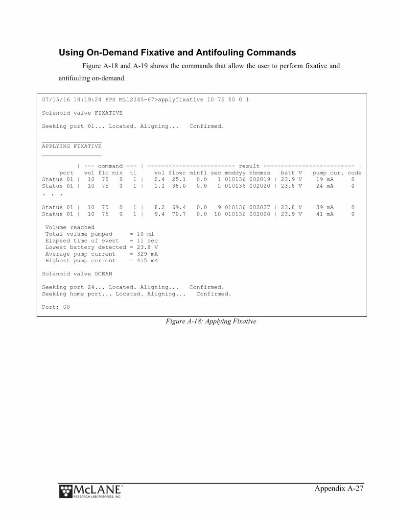
Appendix A-27
Using On-Demand Fixative and Antifouling Commands
Figure A-18 and A-19 shows the commands that allow the user to perform fixative and
antifouling on-demand.
Figure A-18: Applying Fixative
07/15/16 10:19:24 PPS ML12345-67>applyfixative 10 75 50 0 1 Solenoid valve FIXATIVE Seeking port 01... Located. Aligning... Confirmed. _________________ APPLYING FIXATIVE _________________ | --- command --- | ------------------------- result -------------------------- | port vol flo min tl vol flowr minfl sec mmddyy hhmmss batt V pump cur. code Status 01 | 10 75 0 1 | 0.4 25.1 0.0 1 010136 002019 | 23.9 V 19 mA 0 Status 01 | 10 75 0 1 | 1.1 38.0 0.0 2 010136 002020 | 23.8 V 24 mA 0 . . . Status 01 | 10 75 0 1 | 8.2 69.4 0.0 9 010136 002027 | 23.8 V 39 mA 0 Status 01 | 10 75 0 1 | 9.4 70.7 0.0 10 010136 002028 | 23.9 V 41 mA 0 Volume reached Total volume pumped = 10 ml Elapsed time of event = 11 sec Lowest battery detected = 23.8 V Average pump current = 329 mA Highest pump current = 415 mA Solenoid valve OCEAN Seeking port 24... Located. Aligning... Confirmed. Seeking home port... Located. Aligning... Confirmed. Port: 00

Appendix A-28
Figure A-19: Applying Antifouling
07/15/16 10:15:44 PPS ML12345-67>antifoulflush 10 75 50 0 Seeking port 24... Located. Aligning... Confirmed. _________________ ANTIFOULING FLUSH _________________ | --- command --- | ------------------------- result -------------------------- | port vol flo min tl vol flowr minfl sec mmddyy hhmmss batt V pump cur. code Status 24 | 10 75 50 1 | 0.4 22.6 0.0 1 010136 001611 | 23.9 V 18 mA 0 Status 24 | 10 75 50 1 | 1.0 35.5 0.0 2 010136 001612 | 23.8 V 26 mA 0 Status 24 | 10 75 50 1 | 1.7 44.7 0.0 3 010136 001613 | 23.9 V 31 mA 0 . . . Status 24 | 10 75 50 1 | 8.0 69.4 0.0 9 010136 001619 | 23.8 V 45 mA 0 Status 24 | 10 75 50 1 | 9.1 71.1 0.0 10 010136 001620 | 23.7 V 43 mA 0 Volume reached Total volume pumped = 10 ml Elapsed time of event = 11 sec Lowest battery detected = 23.7 V Average pump current = 358 mA Highest pump current = 438 mA Seeking home port... Located. Aligning... Confirmed.
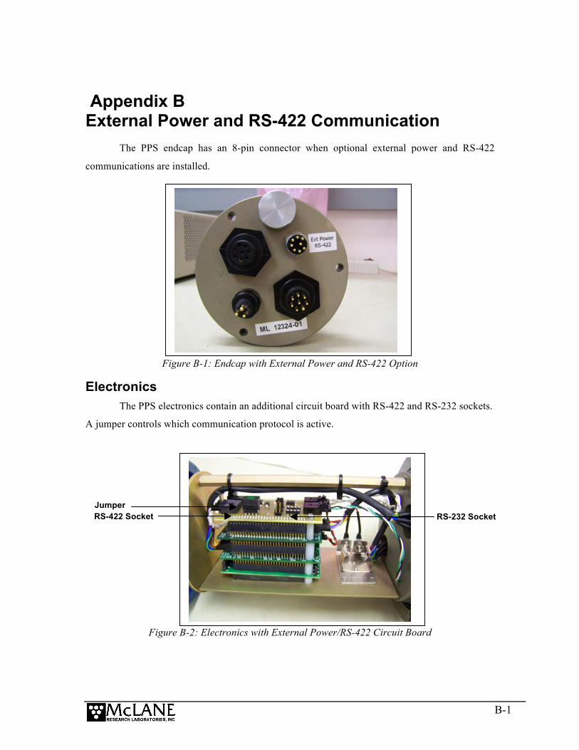
B-1
Appendix B External Power and RS-422 Communication
The PPS endcap has an 8-pin connector when optional external power and RS-422
communications are installed.
Figure B-1: Endcap with External Power and RS-422 Option
Electronics The PPS electronics contain an additional circuit board with RS-422 and RS-232 sockets.
A jumper controls which communication protocol is active.
Figure B-2: Electronics with External Power/RS-422 Circuit Board
RS-422 Socket RS-232 Socket Jumper
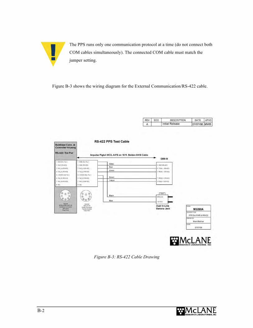
B-2
The PPS runs only one communication protocol at a time (do not connect both
COM cables simultaneously). The connected COM cable must match the
jumper setting.
Figure B-3 shows the wiring diagram for the External Communication/RS-422 cable.
Figure B-3: RS-422 Cable Drawing

B-3
Power Requirements The external power specification is 32 to 36 Volts DC. RS-422 communication is
designed for use with external power. Using RS-422 communication with battery power is not
recommended because the energy draw is 2.7 mA during lower power sleep. This draw is not an
issue under external power, but places a significant drain on battery power (RS-232
communication draws .30 mA from the battery in low power sleep).
Estimated Battery Endurance Calculation with RS-422 Communication The section that follows provides values and an estimated battery endurance calculation
with RS-422 communication. This example uses a one-year deployment. The values for pumping
or moving the valve include the current drain of the controller, which is awake during valve
rotation and pumping.
Controller unit 3.0 mA
Controller unit in low power sleep (LPS) mode 2.7 mA
Pumping 160 mA
Moving the valve from one port to the next 0.23 mAh (2.7 seconds)
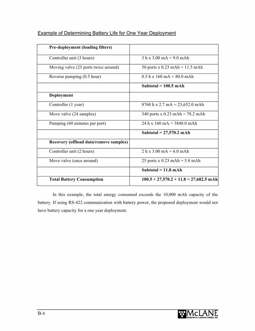
B-4
Example of Determining Battery Life for One Year Deployment
Pre-deployment (loading filters)
Controller unit (3 hours) 3 h x 3.00 mA = 9.0 mAh
Moving valve (25 ports twice around) 50 ports x 0.23 mAh = 11.5 mAh
Reverse pumping (0.5 hour) 0.5 h x 160 mA = 80.0 mAh
Subtotal = 100.5 mAh
Deployment
Controller (1 year) 8760 h x 2.7 mA = 23,652.0 mAh
Move valve (24 samples) 340 ports x 0.23 mAh = 78.2 mAh
Pumping (60 minutes per port) 24 h x 160 mA = 3840.0 mAh
Subtotal = 27,570.2 mAh
Recovery (offload data/remove samples)
Controller unit (2 hours) 2 h x 3.00 mA = 6.0 mAh
Move valve (once around) 25 ports x 0.23 mAh = 5.8 mAh
Subtotal = 11.8 mAh
Total Battery Consumption 100.5 + 27,570.2 + 11.8 = 27,682.5 mAh
In this example, the total energy consumed exceeds the 10,000 mAh capacity of the
battery. If using RS-422 communication with battery power, the proposed deployment would not
have battery capacity for a one year deployment.
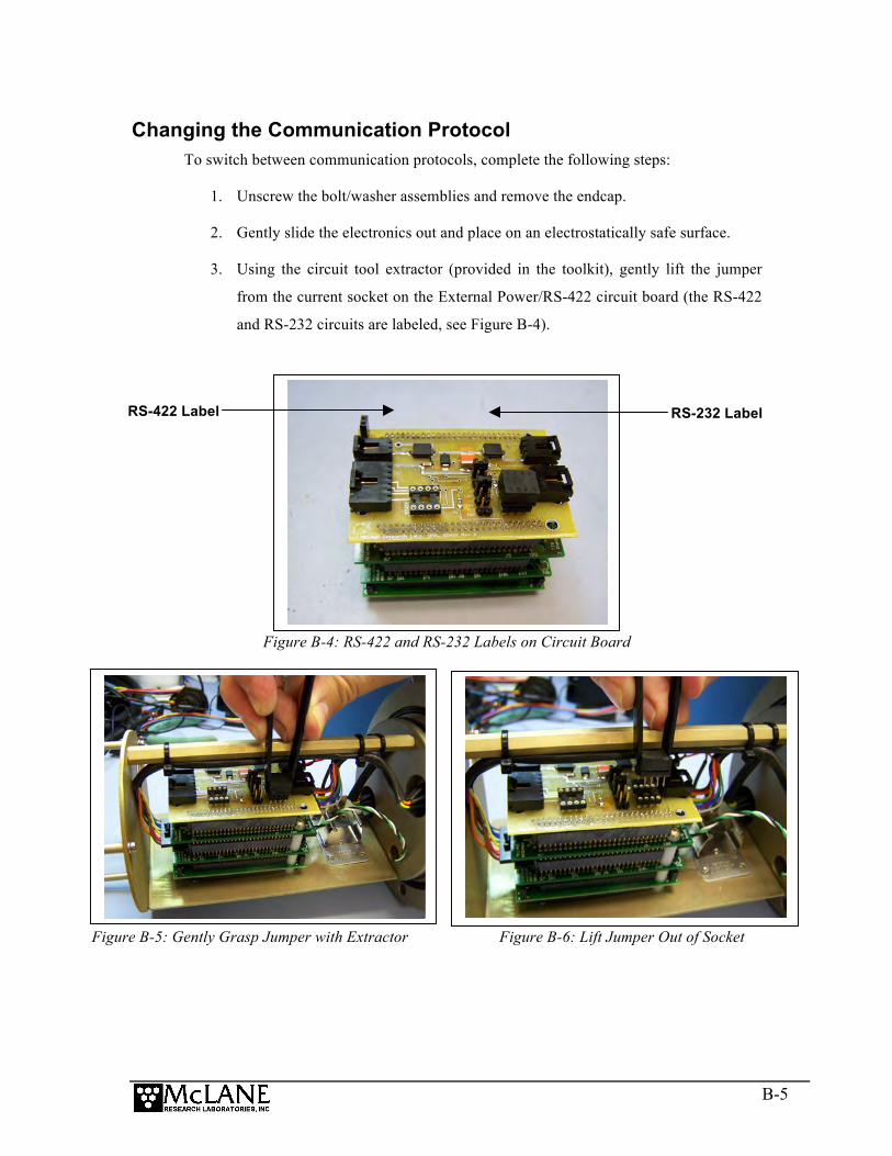
B-5
Changing the Communication Protocol To switch between communication protocols, complete the following steps:
1. Unscrew the bolt/washer assemblies and remove the endcap.
2. Gently slide the electronics out and place on an electrostatically safe surface.
3. Using the circuit tool extractor (provided in the toolkit), gently lift the jumper
from the current socket on the External Power/RS-422 circuit board (the RS-422
and RS-232 circuits are labeled, see Figure B-4).
Figure B-4: RS-422 and RS-232 Labels on Circuit Board
Figure B-5: Gently Grasp Jumper with Extractor Figure B-6: Lift Jumper Out of Socket
RS-422 Label RS-232 Label

B-6
4. Place the jumper in the other socket and press down firmly to secure in place.
Figure B-7: Place the Jumper in Socket Figure B-8: Press to Secure Jumper
5. Slide the electronics chassis back into the controller housing and secure the
endcap.

C-1
Appendix C Training Videos
There is a priming and a battery replacement training video available for the PPS. These
videos are included on the media that ships with a new sampler and can also be downloaded from
the McLane website at:
http://mclanelabs.com/phytoplankton-sampler/pps-videos/.
A description of each video and content is provided below for reference.
Video Content
Priming the PPS Illustrates a sample of the PPS priming step that clears lines and valve ports of trapped air. For the complete and most up to date priming procedure, refer to the PPS User Manual.
Replacing the Batteries in the Drop-in
Holder
Explains the correct orientation for replacing batteries using a drop-in battery holder.

C-2
Notes