vtt publications 552 espoo 2004 antti o. niskanen … incentive for this work was obtained when i...
TRANSCRIPT

Tätä julkaisua myy Denna publikation säljs av This publication is available from
VTT TIETOPALVELU VTT INFORMATIONSTJÄNST VTT INFORMATION SERVICEPL 2000 PB 2000 P.O.Box 2000
02044 VTT 02044 VTT FIN–02044 VTT, FinlandPuh. (09) 456 4404 Tel. (09) 456 4404 Phone internat. +358 9 456 4404Faksi (09) 456 4374 Fax (09) 456 4374 Fax +358 9 456 4374
ISBN 951–38–6420–0 (soft back ed.) ISBN 951–38–6421–9 (URL: http://www.vtt.fi/inf/pdf/)ISSN 1235–0621 (soft back ed.) ISSN 1455–0849 (URL: http://www.vtt.fi/inf/pdf/)
ESPOO 2004 VTT PUBLICATIONS 552
Antti O. Niskanen
Control of Quantum Evolution andJosephson Junction Circuits
Ever since Peter Shor's ground-breaking discovery in 1994 of an algorithmcapable of factoring large integers on a quantum-mechanical computerexponentially faster than using any known classical method, research onquantum computing has boomed. Quantum information – a unique mixtureof computer science, physics and mathematics – has developed into a newbranch of information theory. On the experimental side, physicists frommany different disciplines including atomic, solid-state and low-temperature physics, as well as optics, are striving today towards a practicalquantum computer. All the candidate quantum bit technologies have onething in common: They rely on the controlled time-evolution of a closedquantum system, a seemingly paradoxical task. This work investigates thetemporal control of various quantum systems. While the bulk of the workis theoretical, also experimental results are reported. The topics discussedinclude both geometrical and dynamical quantum computing as well asadiabatic charge pumping. Particular attention is paid to Josephsonjunction systems.


VTT PUBLICATIONS 552
Control of Quantum Evolution and Josephson Junction
Circuits
Antti O. Niskanen VTT Information Technology
Dissertation for the degree of Doctor of Science in Technology to be presented with due permission of the Department of Engineering Physics
and Mathematics for public examination and debate in Auditorium F1 at Helsinki University of Technology (Espoo, Finland)
on the 26th of November, 2004, at 12 noon.
ISBN 951–38–6420–0 (soft back ed.) ISSN 1235–0621 (soft back ed.) ISBN 951–38–6421–9 (URL: http://www.vtt.fi/inf/pdf/) ISSN 1455–0849 (URL: http://www.vtt.fi/inf/pdf/) Copyright © VTT Technical Research Centre of Finland 2004 JULKAISIJA – UTGIVARE – PUBLISHER VTT, Vuorimiehentie 5, PL 2000, 02044 VTT puh. vaihde (09) 4561, faksi (09) 456 4374 VTT, Bergsmansvägen 5, PB 2000, 02044 VTT tel. växel (09) 4561, fax (09) 456 4374 VTT Technical Research Centre of Finland, Vuorimiehentie 5, P.O.Box 2000, FIN–02044 VTT, Finland phone internat. + 358 9 4561, fax + 358 9 456 4374 VTT Tietotekniikka, Tietotie 3, PL 1207, 02044 VTT puh. vaihde (09) 4561, faksi (09) 456 7012 VTT Informationsteknik, Datavägen 3, PB 1207, 02044 VTT tel. växel (09) 4561, fax (09) 456 7012 VTT Information Technology, Tietotie 3, P.O.Box 1207, FIN–02044 VTT, Finland phone internat. + 358 9 4561, fax + 358 9 456 7012
Technical editing Leena Ukskoski Otamedia Oy, Espoo 2004

3
Niskanen, Antti O. Control of Quantum Evolution and Josephson Junction Circuits. Espoo 2004. VTTPublications 552. 46 p. + app. 61 p.
Keywords quantum systems, quantum mechanics, quantum computing, quantum algorithms, Cooperpair pumping
Abstract Ever since Peter Shor's ground-breaking discovery in 1994 of an algorithm capable of factoring large integers on a quantum-mechanical computer exponentially faster than using any known classical method, research on quantum computing has boomed. Quantum information – a unique mixture of computer science, physics and mathematics – has developed into a new branch of information theory. On the experimental side, physicists from many different disciplines including atomic, solid-state and low-temperature physics, as well as optics, are striving today towards a practical quantum computer. All the candidate quantum bit (qubit) technologies have one thing in common: They rely on the controlled time-evolution of a closed quantum system, a seemingly paradoxical task.
In this Thesis the temporal control of quantum systems is studied. The topics included can be divided into two according to the type of temporal evolution; geometrical or dynamical. Geometrical realization-independent methods for quantum computing are studied first. Then the study is extended into dynamical quantum computing and the so-called Josephson charge-qubit register is considered as a test bench. Finally, a spin-off application of the geometrical evolution of a Josephson junction system is studied, i.e. Cooper pair pumping. A novel Cooper pair pump, the Cooper pair "sluice", is introduced.
The work on quantum computing reported in this Thesis is theoretical while the Cooper pair "sluice" is studied both theoretically and experimentally. Numerical simulations, both sequential and parallel, are used extensively throughout the Thesis. The experiments were carried out under cryogenic mK conditions and the sample fabrication was done using e-beam nanolithography.
Because the execution time of a quantum algorithm is always limited by the inevitable process of decoherence, it is important to utilize any measure available for accelerating quantum computations. It is found that practical quantum algorithms could greatly benefit from classical computer-aided optimization. Moreover, it is found that even a modest demonstrator of a full quantum algorithm using Josephson charge qubits is just barely realizable within present-day coherence times. However, the experimental part of this Thesis shows clear evidence of the functioning of the "sluice". While the worldwide effort of improving the coherence properties of qubits is underway, the "sluice" could well find practical use, e.g., in metrology in the foreseeable future.
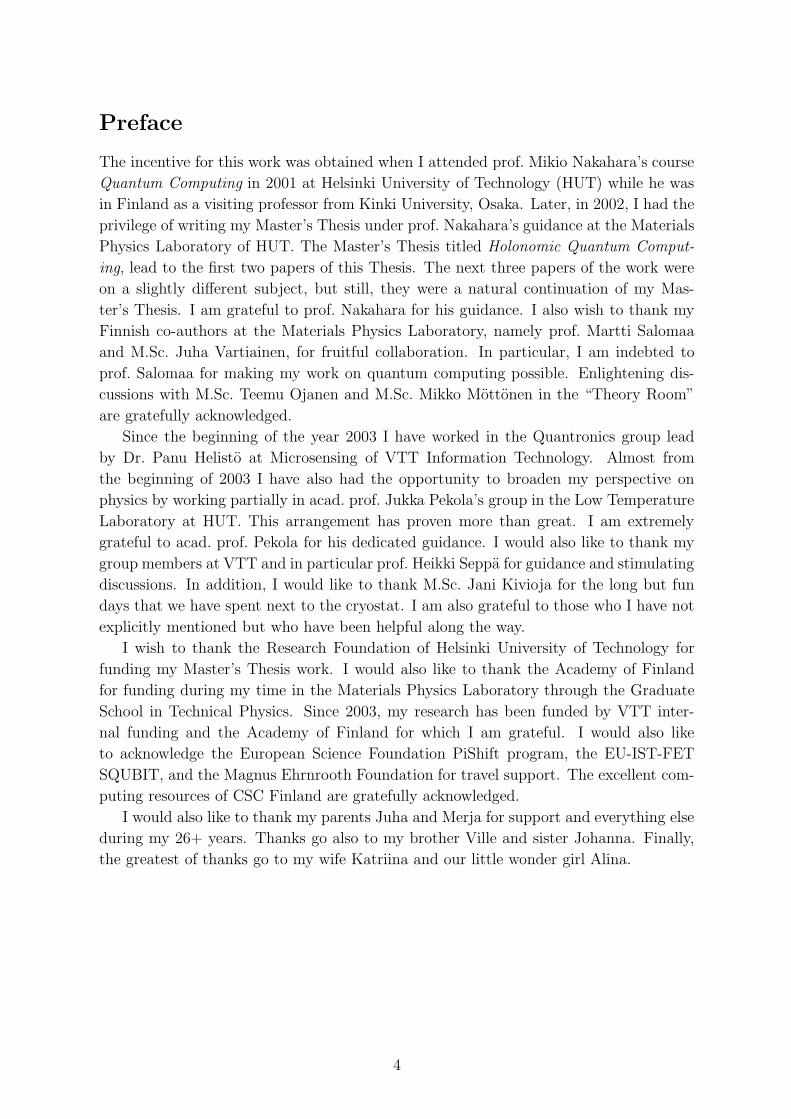
Preface
The incentive for this work was obtained when I attended prof. Mikio Nakahara’s course
Quantum Computing in 2001 at Helsinki University of Technology (HUT) while he was
in Finland as a visiting professor from Kinki University, Osaka. Later, in 2002, I had the
privilege of writing my Master’s Thesis under prof. Nakahara’s guidance at the Materials
Physics Laboratory of HUT. The Master’s Thesis titled Holonomic Quantum Comput-
ing, lead to the first two papers of this Thesis. The next three papers of the work were
on a slightly different subject, but still, they were a natural continuation of my Mas-
ter’s Thesis. I am grateful to prof. Nakahara for his guidance. I also wish to thank my
Finnish co-authors at the Materials Physics Laboratory, namely prof. Martti Salomaa
and M.Sc. Juha Vartiainen, for fruitful collaboration. In particular, I am indebted to
prof. Salomaa for making my work on quantum computing possible. Enlightening dis-
cussions with M.Sc. Teemu Ojanen and M.Sc. Mikko Mottonen in the “Theory Room”
are gratefully acknowledged.
Since the beginning of the year 2003 I have worked in the Quantronics group lead
by Dr. Panu Helisto at Microsensing of VTT Information Technology. Almost from
the beginning of 2003 I have also had the opportunity to broaden my perspective on
physics by working partially in acad. prof. Jukka Pekola’s group in the Low Temperature
Laboratory at HUT. This arrangement has proven more than great. I am extremely
grateful to acad. prof. Pekola for his dedicated guidance. I would also like to thank my
group members at VTT and in particular prof. Heikki Seppa for guidance and stimulating
discussions. In addition, I would like to thank M.Sc. Jani Kivioja for the long but fun
days that we have spent next to the cryostat. I am also grateful to those who I have not
explicitly mentioned but who have been helpful along the way.
I wish to thank the Research Foundation of Helsinki University of Technology for
funding my Master’s Thesis work. I would also like to thank the Academy of Finland
for funding during my time in the Materials Physics Laboratory through the Graduate
School in Technical Physics. Since 2003, my research has been funded by VTT inter-
nal funding and the Academy of Finland for which I am grateful. I would also like
to acknowledge the European Science Foundation PiShift program, the EU-IST-FET
SQUBIT, and the Magnus Ehrnrooth Foundation for travel support. The excellent com-
puting resources of CSC Finland are gratefully acknowledged.
I would also like to thank my parents Juha and Merja for support and everything else
during my 26+ years. Thanks go also to my brother Ville and sister Johanna. Finally,
the greatest of thanks go to my wife Katriina and our little wonder girl Alina.
4

List of Publications
This Thesis is a review of the author’s work on the control of the temporal evolution of
quantum systems in general and of Josephson junction systems in particular. It consists
of an overview and the following publications:
I. A. O. Niskanen, M. Nakahara, and M. M. Salomaa, Realization of arbitrary gates
in holonomic quantum computation, Physical Review A 67, 012319 (2003).
II. A. O. Niskanen, M. Nakahara, and M. M. Salomaa, Optimal holonomic quantum
gates, Quantum Information and Computation 2, 560–577 (2002).
III. A. O. Niskanen, J. J. Vartiainen, and M. M. Salomaa, Optimal multiqubit operations
for Josephson charge qubits, Physical Review Letters 90, 197901 (2003).
IV. J. J. Vartiainen, A. O. Niskanen, M. Nakahara, and M. M. Salomaa, Acceleration
of quantum algorithms using three-qubit gates, International Journal of Quantum
Information 2, 1–10 (2004).
V. J. J. Vartiainen, A. O. Niskanen, M. Nakahara, and M. M. Salomaa, Implementing
Shor’s algorithm on Josephson charge qubits, Physical Review A 70, 012319 (2004).
VI. A. O. Niskanen, J. P. Pekola, and H. Seppa, Fast and accurate single-island charge
pump: Implementation of a Cooper pair pump, Physical Review Letters 91, 177003
(2003).
VII. A. O. Niskanen, J. M. Kivioja, H. Seppa, and J. P. Pekola, Evidence of Cooper
pair pumping with combined flux and voltage control, submitted, 4 pages (2004);
cond-mat/0410758.
Throughout the overview the above articles are referred to by their Roman numerals.
5

Author’s Contribution
The research reported in this Thesis has been carried out in the Materials Physics Labo-
ratory at Helsinki University of Technology in 2002 (Publications I–III) and in 2003–2004
(Publications VI and VII) jointly at Microsensing of VTT Information Technology and
the Low Temperature Laboratory at Helsinki University of Technology. During 2003–
2004 the author has also continued, out of academic interest, part-time the research
initiated at the Materials Physics Laboratory in 2002 (Publications IV and V).
The author has had a central role in all aspects of the work reported in this The-
sis. The author has written the manuscripts for Publications I–III, VI and VII and
actively participated in writing Publications IV and V. The computer programs used in
Publications I, II and VI were developed by the author. The author was a co-developer
of the parallel programs and methods used in Publications III–V, which are based on
the author’s original sequential algorithms used in Publications I and II. Publication VI,
the theory of the Cooper pair “sluice”, is based on the author’s original idea. Publica-
tion VII is a report of the experimental verification of this idea. The author fabricated
the samples used in the experiment, actively participated in the low-temperature mea-
surements and analyzed the data of Publication VII.
In addition, the author has presented the results of the work at major international
conferences including the Erato Workshop on Quantum Information Science (EQIS)
in Tokyo (Japan) 2002, the 6th European Conference on Applied Superconductivity
(EUCAS) in Sorrento (Italy) 2003 and the 39th Rencontres de Moriond on Quantum
Information and Decoherence in Nanosystems in La Thuile (Italy) 2004. Some results of
the Thesis were also presented in the Applied Superconductivity Conference (ASC) in
Jacksonville (Florida, USA) 2004.
6

Contents
Abstract 3
Preface 4
List of Publications 5
Author’s Contribution 6
1 Introduction 9
2 Controlled Evolution of Quantum Systems 112.1 Quantum mechanics and dynamical temporal evolution . . . . . . . . . . 11
2.2 Geometrical temporal evolution . . . . . . . . . . . . . . . . . . . . . . . 13
3 Optimization of Quantum Algorithms 163.1 Quantum computing . . . . . . . . . . . . . . . . . . . . . . . . . . . . . 16
3.2 Adiabatic non-Abelian quantum gates . . . . . . . . . . . . . . . . . . . 19
3.3 Non-adiabatic Josephson charge-qubit gates . . . . . . . . . . . . . . . . 22
4 Cooper Pair Pumping 294.1 Adiabatic Cooper pair pumping and Berry’s phase . . . . . . . . . . . . . 29
4.2 Cooper pair “sluice” . . . . . . . . . . . . . . . . . . . . . . . . . . . . . 32
4.3 Experiments on the “sluice” . . . . . . . . . . . . . . . . . . . . . . . . . 35
5 Conclusions 39
References 41
Appendices: Publications I–VII
7

8

1 Introduction
The temporal control of pure quantum systems has two competing requirements. On one
hand, it is desired that the system under scrutiny is well isolated from its environment
such that the dynamics may be assumed to be unitary. On the other hand, however,
any temporal control implies a time dependence in the Hamiltonian which can only be
an effective approximation and a result of an interaction with the environment such
that the system cannot stay pure indefinitely. Despite this, ever since the emergence of
Shor’s algorithm [1] for factoring large composite integers on a quantum computer [2–5]
the control of the temporal evolution of quantum systems has been a topic of intensive
investigations in physics. The “killer application” of Shor’s algorithm would be the
breaking of the RSA cryptosystem. This could have a remarkable societal impact, and
not necessarily a negative one. To complement the possible emergence of a quantum
computer, quantum cryptography [6] is quite advanced already today. Nevertheless, in
order to perform calculations on a quantum computer, the quantum programmer needs
to have full control over the time-evolution of the system. Moreover, the system needs to
stay pure in the quantum-mechanical sense. It is possible to have quantum control that
does not maintain the purity, and the difference between the control of an impure state
and that of a pure state should be distinguished. Roughly speaking, in the control of
pure states not only the probabilities of different states but also the quantum-mechanical
phases are of interest. This Thesis discusses the control of pure or almost pure quantum
systems.
Quantum control has been studied in the past particularly in the context of nuclear
magnetic resonance (NMR) [7] and, e.g., within molecular dynamics [8]. Quite com-
plicated quantum-computing experiments have also been carried out in NMR with the
most spectacular achievement of a seven-qubit algorithm for factoring the number fif-
teen [9]. The topic of controlling the macroscopic quantum state of a system such as the
nanoelectronic superconducting Cooper pair box [10] is less thoroughly explored. Never-
theless, many steps have been taken in recent years towards an experimental realization
of a Josephson junction based quantum computer. In the experiments by Nakamura et
al. [11–13], the coherent oscillations of a Cooper pair box were first observed. The coher-
ent operation of a coupled Cooper pair box system has also been demonstrated [14, 15].
The dual realization, i.e. the superconducting qubit taking advantage of the flux degree
of freedom [16, 17] has been experimentally verified as well [18, 19]. The macroscopic
coherent behavior of a current-biased large Josephson junction, or the phase qubit, was
recently realized [20,21] with as high as µs coherence times reported in Ref. [20]. Coher-
ence times on the same order were measured in the so-called quantronium circuit [22]
in Saclay. A generalization of the current-biased Josephson junction, the current-biased
SQUID, has also been demonstrated to exhibit coherent behavior [23]. Exotic scenarios,
such as the tetrahedral qubit [24], have been suggested as well. For a review of various
superconducting qubits up to year 2001 see in particular Ref. [25].
The control of adiabatic Cooper pair pumps (CPPs) [26–28] is an instance of the geo-
metrical control of a superconducting system similar to superconducting qubits. While in
9
superconducting qubits the control is typically achieved via ordinary dynamical temporal
evolution, the CPPs are controlled adiabatically and cyclically such that no transitions
between states occur. In quantum computing unitary transformations are pursued while
in Cooper pair pumping the time-integral of the current is of interest. It is however
possible, at least in principle, to achieve also general unitary transformations via adia-
batic evolutions as holonomies. This branch of quantum information is called holonomic
quantum computing (HQC) [29]. This Thesis contains examples of both adiabatic and
dynamical quantum computing as well as Cooper pair pumping.
The Overview is organized as follows. Section 2 briefly discusses the unitary evolu-
tion of quantum systems in general and the concept of geometrical evolution in partic-
ular. Section 3 discusses the optimization of quantum algorithms developed in detail in
Publications I–V. Finding unitary operations within a realization-independent model of
holonomic quantum computing (Publications I and II) is studied first. Then the con-
struction of dynamical quantum gates (Publications III–V) for a model identical to a
Cooper pair box array is explored. The highlight of the Section is a theoretical study
of carrying out the simplest nontrivial application of Shor’s factorization algorithm on
Josephson charge qubits. The topic of Section 4 is the adiabatic Cooper pair pump
and especially the so-called Cooper pair “sluice” of Publications VI and VII. This topic
is an illustration of the multitude of present-day applications achievable with almost
identical techniques and structures as those intended to be used in quantum computing.
As explained below this device aimed at a metrological application has many common
features with superconducting qubits and it is further closely related to the concept of
Berry’s phase. Cooper pair pumping has been studied extensively in the past but has
never proven even nearly as accurate as, e.g., single-electron pumping [30]. The sluice is
hoped to bridge this gap. Finally, Section 5 is dedicated to a discussion of the results in
this Thesis.
10

2 Controlled Evolution of Quantum Systems
The topics discussed in this Thesis rely on the cyclic control of quantum systems achieved
via manipulating their Hamiltonians in time. That is, in all the applications considered
the parameters of a Hamiltonian go around loops in the parameter space in order to
achieve some desired effect. These controlled cyclic temporal evolutions may roughly
be divided into two main categories: Evolution may be either dynamical or geometri-
cal in nature. Geometrical evolution may arise if the time dependence is slow enough
compared to the relevant energy level separations, i.e., all the controllable parameters
of the Hamiltonian are tuned adiabatically. As the term geometrical implies, only the
geometry of the loop matters and not the speed at which it is traversed. Geometri-
cal, or adiabatic, evolutions may further be divided into Abelian and non-Abelian ones.
Abelian evolutions are commuting, i.e. the order in which the loops are arranged does
not matter, while non-Abelian evolutions do not commute. Abelian evolutions give rise
to Berry’s phase [31] while non-Abelian evolutions may not be characterized by a simple
phase but rather unitary matrices are needed as pointed out by Wilczek and Zee [32].
They are called holonomies.
Decoherence mechanisms and open quantum systems (see, e.g., Ref. [33,34]) are not
considered in detail in this Thesis. Many studies on the decoherence mechanisms in
superconducting circuits exist in the literature, see e.g. Refs. [25, 35–39] and references
therein. In Subsection 2.1 below we give a brief introduction to the concepts of quantum
mechanics that are important for the present work including general dynamical evolu-
tion. We then proceed to discuss geometrical evolution in Subsection 2.2. For a critical
discussion of the fundamentals of quantum mechanics, see e.g. Ref. [40]. Publications
I, II, VI and VII are related to adiabatic evolution while Publications III–V discuss
dynamical evolutions.
2.1 Quantum mechanics and dynamical temporal evolution
The state of a pure quantum system is described by a state vector |ψ〉 in a complete
inner-product space called the Hilbert space. A physical state vector |ψ〉 can always be
normalized to unity 〈ψ|ψ〉 = 1. It may occur, however, that the state is not pure but
rather mixed in which case the system is described with a state operator, or a density
matrix (operator) ρ with Tr ρ = 1. The system is pure if and only if Tr ρ2 = 1 in
which case one may use the state vector to describe the system. Given a state vector,
the corresponding density operator may be formed via ρ = |ψ〉〈ψ|. The state vector
and the state operator are not themselves directly observable quantities in quantum
mechanics. Namely, every observable has an associated self-adjoint operator O = O†. In
the spirit of the statistical interpretation of quantum mechanics, the expectation value
for the kth moment of an observable is given by either 〈Ok〉 = Tr(ρOk
)or alternatively
by 〈Ok〉 = 〈ψ|Ok|ψ〉 in the special case of a pure system. The measurement of the
observable always yields an eigenvalue of the operator O. Even if the state |ψ〉 is not
an eigenstate of O, then owing to the self-adjointness of O we may utilize the complete
11

eigenbasis to expand the state. That is, we may write
|ψ〉 =∑
α
cα|ψα〉, (1)
where O|ψα〉 = ωα|ψα〉,∑
α |cα|2 = 1, 〈ψβ|ψα〉 = δαβ and ωα ∈ R. An ideal projective
measurement will result in ωα with the probability |cα|2. Immediately following the
measurement, the system will reside in the state |ψα〉.For every quantum system, there exists a Hamiltonian operator H which describes the
energy of the system. This dictates the exact form of the temporal evolution. Namely,
the dynamics of an isolated quantum system is governed by the Schrodinger equation
i~d
dt|ψ(t)〉 = H|ψ(t)〉. (2)
The corresponding equation for the density operator is
i~ρ(t) = [H, ρ]. (3)
For a time-independent Hamiltonian Eq. (2) may be simply solved using operator expo-
nentiation, i.e. |ψ(t1)〉 = exp(−iH(t1 − t0)/~)|ψ(t0)〉. If the Hamiltonian has a general
time dependence H ≡ Hq(t) the situation is considerably more complicated since the
Hamiltonian may have a non-vanishing commutator with itself at different instants of
time. In this work the Hamiltonian is taken to depend on a set of tunable parameters.
These parameters are described by a vector-valued function of time q(t). This vector
naturally contains all the parameters that we have control over. We can, even then, still
formally solve for the time evolution using the time-ordering operator T , which results
in
|ψ(t1)〉 = T exp
(
−i∫ t1
t0
Hq(t)dt/~
)
|ψ(t0)〉. (4)
In spite of the integral, the above expression does not involve integration in the ordinary
sense but it is rather a product integral. The effect of T is to arrange a sequence of
operators, each of which is associated with an instant in time, such that the operators
associated with earlier times are always to the right from those associated with later
instants. Regardless of the exact details, however, the dynamics of an isolated quantum
system is always unitary. We may write |ψ(t1)〉 = U(t1, t0)|ψ(t0)〉 where in the general
case the unitary operator U(t1, t0) is given by
U(t1, t0) = T exp
(
−i∫ t1
t0
Hq(t)dt/~
)
. (5)
Due to unitarity, the quantum-temporal evolution of a closed system is always reversible:
U(t1, t0)−1 = U(t1, t0)
†. The norm is also preserved, i.e.
〈ψ(t1)|ψ(t1)〉 = 〈ψ(t0)|U(t1, t0)†U(t1, t0)|ψ(t0)〉 = 〈ψ(t0)|ψ(t0)〉 = 1, (6)
which is consistent with the probability interpretation of quantum mechanics. The
unitary temporal evolution of a mixed state may be expressed also very concisely as
ρ(t1) = U(t1, t0)ρ(t0)U(t1, t0)†.
12

Equation (5) is quite general and comprises all forms of unitary evolution, i.e. both
adiabatic and non-adiabatic behaviors. It serves as the natural starting point for numer-
ical calculations. Depending on the application, one either aims at realizing a certain
unitary evolution (quantum computing) or a certain consequence of evolutions (e.g.,
quantum pumping). The unitarity of the temporal evolution only breaks down when
the system in consideration is no longer isolated. The quantum measurement mentioned
briefly above is clearly non-unitary and, as a matter of fact, it is just through interactions
that the actual measurements take place. This brings us to the problem of combining
quantum systems. Two quantum systems with separate Hilbert spaces may be combined
by considering their tensor product. That is, for any |ψ1〉 (ρ1) and |ψ2〉 (ρ2) the com-
bined state is |ψ1〉 ⊗ |ψ2〉 (ρ1 ⊗ ρ2). In the case of finite-dimensional spaces the tensor
product is just the Kronecker product for matrices. The total Hamiltonian is, on the
other hand Htot = H1 ⊗ I + I ⊗ H2. However, it may be that the two systems are
non-isolated such that the total Hamiltonian may not be written as a sum of two terms
each of which acts non-trivially only on the subspace of one of the systems but rather
Htot = H1 ⊗ I + I ⊗H2 + Hint. It may also be the case that two initially separate pure
systems cannot be described by |ψ1〉 ⊗ |ψ2〉. Then the total system is called entangled.
To obtain the state operator for a certain subsystem of a possibly entangled total system
one simply traces over the degrees of freedom of the uninteresting part of the Hilbert
space. That is, if we have two systems 1 and 2, then ρ1 = Tr2ρ is the state operator of
subsystem 1. This partial trace combined with unitary global evolution may result in
non-unitary temporal evolution.
2.2 Geometrical temporal evolution
In the special case when the temporal evolution of a quantum system may be considered
to be adiabatic, Eq. (5) may be further refined. Adiabaticity in quantum mechanics
means that if the quantum system in question, described by some Hamiltonian Hq(t),
is initially in the kth eigenstate of energy, then we may also assume that it stays in the
corresponding kth eigenstate. This is the case when the dynamics is slow compared to
the energy-level separations. Clearly no level crossings can be allowed such that the
ordering of the states is possible and the separations remain nonzero. In this Thesis
we consider only adiabatic systems in the ground state. Thus, for our purposes, the
adiabaticity criterion means that all the related frequencies are much lower than the
resonant frequency between the ground state and the first exited state. This resonant
frequency may of course also depend on time, and thus the condition must hold at all
times.
This basic assumption has quite nontrivial consequences [31,32,41]. For our purposes
it is sufficient to concentrate on what happens to the ground state. Let us assume that
the ground state has g degenerate eigenstates denoted by |0α;q〉 (α = 1, ..., g) and that
no level crossings occur at least between the ground state and the higher excited states.
The eigenvalue of the ground state is εq, such that
Hq|0α;q〉 = εq|0α;q〉 (7)
13

and
〈0α;q|0β;q〉 = δαβ. (8)
Moreover, the eigenvectors of the ground-state subspace are also orthogonal to the higher
excited states. Let us assume that the state of the system is initially any one of orthonor-
mal ground states |α;q(t0)〉 and that the system evolves adiabatically over time t ∈ [t0, t1]
and also that the parameters go around a loop such that q(t0) = q(t1). Then we may
write the state of the system |ψα(t)〉 at time t as
|ψα(t)〉 =
g∑
θ=1
Uθα(t, t0)|0θ;q(t)〉 (9)
with some complex coefficients Uβα(t, t0) that must satisfy Uβα(t0, t0) = δβα. Plugging
this into the Schrodinger equation, multiplying from the left by 〈0β;q(t)| and using the
orthonormality of the states yields
dUβα(t, t0)
dt= −
g∑
θ=1
〈0β;q(t)| ddt|0θ;q(t)〉Uθα(t, t0) − iεq(t)Uβα(t, t0)/~. (10)
This has the solution
U(t, t0) = e−i∫
t
t0εq(τ)dτ/~T exp
(
−∫ t
t0
A(τ)dτ
)
, (11)
where A(t) is a matrix whose entries Aβα(t) are given by
Aβα(t) = 〈0β;q(t)| ddt|0α;q(t)〉. (12)
Neglecting the dynamical phase θdyn = −∫ t
t0εq(τ)dτ/~ for now and introducing the
connection matrices Ai whose elements are
Ai;βα = 〈0β;q| ∂∂qi
|0α;q〉 (13)
allows us to rewrite Eq. (11) at the instant t = t1 as
U(t1, t0) ≡ Uγ = P exp
(
−∮
γ
Aidqi
)
, (14)
where γ is the loop around which we traverse. The quantity Aidqi is sometimes called
the Wilczek-Zee connection one-form. Einstein’s summation convention over all the
components of the control parameter vector, i.e. the index i, is assumed. The path-
ordering operator P is used above. Its operation is similar to that of T .
Now if instead of the state |α;q(t0)〉 we were initially to start from an arbitrary
superposition∑g
α=1 cα|α;q(t0)〉 then at time t1 the state of the system would be
|ψ(t1)〉 =
g∑
α=1
cα|ψα(t1)〉 (15)
14

or
|ψ(t1)〉 =
g∑
α,β=1
Uβα(t1, t0)cα|β;q(t1)〉 =
g∑
α,β=1
(Uγ)βαcα|β;q0〉. (16)
We see form this that Uγ is indeed the unitary matrix that describes how the quantum
state evolves during each loop based at q(t0) = q0. This is called a non-Abelian holonomy
[32,41] in the degenerate case (Publications I and II) and Berry’s phase [31] (Publications
VI and VII) in the nondegenerate case, i.e. Uγ = eiθBerry if g = 1. In the nondegenerate
case we may denote the ground state simply as |0;q〉 and since the path ordering is then
meaningless, Berry’s phase is simply
θBerry = i
∮
γ
〈0;q| ∂∂qi
|0;q〉dqi = i
∮
γ
〈0;q(t)|∇q|0;q(t)〉 · dq. (17)
Thus, the cyclic quantum evolution of the ground state in the adiabatic limit has two con-
tributions; the more-or-less trivial dynamical factor e−i∫ t1t0
εq(t)dt/~ that can be neglected
in e.g. quantum computing applications and the geometrical contribution Uγ . To obtain
some desired holonomic evolution one needs to describe a loop γ in the parameter space
spanned by all the controllable parameters. Whereas in general the speed at which a
loop is traversed plays a role, in the adiabatic evolution only the geometry of the path
(not its parameterization) matters. It may appear at first sight that for a nondegenerate
system in its ground state, Berry’s phase would be meaningless since it only describes a
global phase. This is not the case as will be seen in Section 4 where we discuss Cooper
pair pumps. For universal quantum computation based solely on ground-state adiabatic
control, however, a degenerate system is required.
15
3 Optimization of Quantum Algorithms
Quantum computing is potentially a very spectacular application of the temporal control
of quantum systems. Basically any collection of two-state (or more) quantum systems
that can be controlled, and moreover, the couplings of which we have control over, or
can take into account somehow, is a potential quantum computer. Provided that the
quantum system is sufficiently well isolated from its environment, we may assume the
dynamics to be unitary as in the previous Section. However, the parameters of the
Hamiltonian need to be tunable and thus the isolation must not be perfect. In this
Section we shall first introduce the concept of quantum computing. Many excellent
overviews of this subject may be found in the literature, see e.g. Refs. [2–5]. It will turn
out that a quantum algorithm is nothing but a unitary operator. It is programmed by
finding a proper control pulse q(t) and executed by applying the pulse on the quantum
system. In Subsection 3.2 we consider a realization–independent approach for finding
physical implementations of holonomic quantum computations. Subsection 3.3 describes
a similar approach for finding optimized logical dynamical quantum gates on Josephson
charge qubits. All the methods presented rely on intensive numerical optimization. The
key point of this Section is that instead of using sequences of elementary operations, we
pursue a method of finding direct implementations of single and multiple qubit operations
in a single pulse sequence. We demonstrate that it is in practice much more advantageous
to implement a quantum algorithm via first finding, using ordinary computers, a direct
implementation for as large a multiqubit operation as possible and then implementing
this optimized operation on a quantum computer rather than using some limited set of
elementary operations.
3.1 Quantum computing
Quantum computers can solve certain problems that are classically considered to require
exponential resources (time and space) in polynomial time and space. The idea of quan-
tum computing is to take advantage of the global properties of a very high-dimensional
multi-partite Hilbert space. A quantum computer is a quantum system typically con-
sisting of multiple two-state subsystems called quantum bits, or qubits. A prototype
for a qubit is the spin degree of freedom of a spin-1/2 particle. Information is encoded
in the states of the qubits such that one state of the qubit corresponds to the “0” of a
classical digital bit while the other corresponds to “1”. Let us denote the basis states
of the collection of N qubits by |0j〉 and |1j〉 with j ∈ {1, . . . , N}. One often uses the
vector notation
|0j〉 =
(1
0
)
and |1j〉 =
(0
1
)
(18)
for these states. If the states of the individual qubits are |ψj〉 with ψj = 0, 1 then the
state of the composite system may be expressed using the tensor product as
|Ψ〉 =
N⊗
j=1
|ψi〉 = |ψN〉 ⊗ . . .⊗ |ψ1〉 = |ψN . . . ψ1〉 , (19)
16

where the last form is an often used abbreviation. In the absence of superpositions
the quantum information contained in this quantum register is interpreted just like the
information in a classical bit register; the data is just a binary number. The strength
of a quantum computer, however, emerges from the fact that the quantum register may
evolve into a superposition of all the possible 2N states. That is, if |Ψα〉 is some N -qubit
state corresponding to a binary number, then the state of the quantum computer can be
|Ψ〉 =
2N
∑
α=1
cα|Ψα〉 , (20)
with 〈Ψ|Ψ〉 = 1. The prototype of an entangled superposition is the so-called Bell state
for two qubits
|Ψ〉 =1√2
(|0〉 ⊗ |0〉 + |1〉 ⊗ |1〉) . (21)
The interpretation of the data contained in this register is entirely non-classical; with
probability one half the bits are either both zeros or ones. Moreover, the measurement of
one of the qubits immediately tells us the result that the measurement of the second qubit
would give. This has some very counterintuitive implications and the interpretation of
this kind of state even confused Einstein [42]. Entangled states, such as the Bell state
above, can be used for so-called (deterministic) quantum teleportation that has been
recently realized using ion traps [43, 44].
The quantum algorithm is nothing but a 2N -dimensional unitary operator of Eq. (5)
which dictates the temporal evolution of the quantum register, i.e.
|Ψ(t1)〉 = U(t1, t0)|Ψ(t0)〉. (22)
The evolution of the quantum computer is governed by the Hamiltonian Hq(t) whose
time-dependence the experimenter must have control over. The control is mediated by
the parameters q(t) and different formal expressions for the algorithm U can be derived
as discussed in the previous Section. Clearly the number of degrees of freedom for the
algorithm is immense; it takes 22N − 1 real numbers to describe the most general kind
of an algorithm while for applications N � 100. Luckily, practical algorithms exist
too. Typically, we would desire the operator U to perform, for instance, the quantum
part of Shor’s algorithm [1] or the Grover search [45] both of which can be carried
out by applying a polynomial number of so-called elementary operations [46]. Shor’s
algorithm can factor large integers in polynomial time, which is otherwise believed to be
exponentially hard, while Grover’s search can be used to carry out a database search of
an unsorted database in time proportional to the square root of the entries in it. The best
known decompositions of arbitrary multiqubit gates have been reported in Refs. [47,48]
but, nevertheless, the number of required gates scales exponentially with the number of
qubits.
The unique property of quantum mechanics that makes quantum computing attrac-
tive is that unitary operator “processes” all orthogonal basis states independently. In
other words, the quantum algorithm may process 2N different inputs at once if the regis-
ter is initialized for instance in an equal superposition. This is sometimes called quantum
17

parallelism. The task carried out e.g. in Shor’s algorithm is the evaluation of a certain
modular function, see e.g. Refs. [1, 2] or Paper V. With N ∼ 103 the number of states
is already immense and beyond the capacity of all classical computers. However, after
the unitary temporal evolution one has to measure the state of the system. Each qubit
is found in either the state |0〉 or |1〉. If the state of the register prior to measurement is
|Ψ〉, then the probability of obtaining the result |Ψ〉 =⊗N
j=1 |ψj〉 (ψj = 0 or ψj = 1) is
given by
P (Ψ) = 〈Ψ|Ψ〉〈Ψ|Ψ〉 = |〈Ψ|Ψ〉|2. (23)
This is the tricky part. No matter how many orthogonal basis states have non-vanishing
amplitudes in the superposition, upon measurement only one of them survives. Moreover,
the result is stochastic. The quantum measurement makes it impossible to obtain more
than one output. The trick that can be used then is to further process the information
in the quantum register before measurement and to look for “global” properties in it. In
Shor’s algorithm one is interested in the period of the modular function and luckily the
quantum equivalent of the fast Fourier transform may be carried out efficiently. This
causes the quantum register to form strong interference patterns and upon measurement
it is possible, stochastically, to deduce the period. Thus the true strength of quantum
computing is only unleashed in a certain class of applications in which some well-defined
global property is known.
We list the requirements for practical quantum computing following DiVincenzo [49].
One needs to have:
• a scalable physical system with well characterized qubits
• the ability to initialize the state of the qubits to a simple fiducial state
• long relevant decoherence times, much longer than the gate operation time
• a universal set of quantum gates
• a qubit-specific measurement capability.
All of these points are necessary and it seems that all the existing suggestions for physical
realizations of quantum computing possess strengths in some of these areas but not in
each one of them. In this work we are primarily interested in how to carry out the
unitary transformations, i.e. the quantum gates.
As mentioned above, typically the unitary operator U is decomposed into a sequence
of so-called elementary gates [46] that act non-trivially only on one or two qubits. These
are analogous with the basic logical operations of an ordinary computer. The physical
implementation for these is often found by hand and the Hamiltonian is sometimes even
considered piecewise constant in time. This leads to abrupt switchings in the parameter
sequences which are hard if not impossible to implement. Finite rise and fall times of
real pulses lead to errors [50]. Furthermore, in general only a limited number of logically
different gates are assumed to be available. Thus the logical gate sequences may get
prohibitively long. In the next two subsections methods for finding arbitrary single and
18

multiple qubit gates avoiding abrupt switchings are considered. The motivation for this is
that the more complicated gates we may perform in a single step, the more of the valuable
execution time we save. This is extremely important due to the presence of decoherence
which inevitably limits the total execution time of the algorithm. In Subsection 3.2,
methods for finding the adiabatic loop γ in the control-parameter space for any one-qubit
and two-qubit operation for a certain toy model is presented, while in Subsection 3.3
control sequences realizing up to three-qubit operations for Josephson charge qubits are
found. The developments presented here have recently obtained experimental verification
when Nakahara et al. demonstrated [51] the acceleration of the two-qubit Grover search
at best by four times by first optimizing the algorithm and then by carrying it out
experimentally in an NMR setup.
3.2 Adiabatic non-Abelian quantum gates
Holonomic quantum computing (HQC) [29, 52–55] is a subfield of quantum information
processing in which the quantum register is assumed to be fully degenerate and the
quantum control is implemented using Eq. (14). The reason for studying holonomic
quantum computing is that it is hoped to be robust against decoherence due to the
degeneracy of the spectrum. A clear benefit is also the fact that the exact timing of the
pulses is not crucial since the evolution is purely geometrical as long as the adiabaticity
is maintained. Additional features include the absence of unwanted phases on idle qubits
that inevitably accumulate in any scenario in which the logical states are energetically
different.
Thus in HQC each unitary gate is associated with a loop in the parameter space,
and a sequence of loops forms the full quantum algorithm. Holonomic or adiabatic
non-Abelian gates in a three-state model are studied in papers I and II. The results
obtained are quite general and are not limited to any particular physical system. For
various suggestions for the realization of non-Abelian holonomies with Josephson junc-
tion structures, see Refs. [56–58]. Also optical [59] and semiconductor [60] HQC has
been suggested. Berry’s Abelian geometrical phase has been envisaged to be used for
universal quantum computation in superconducting systems by Falci et al. [61], but there
the system under study is not in the ground state such that differences in Berry phases
are of interest and, furthermore, sudden changes in the parameters are also used. In
HQC purely ground state systems and strictly adiabatic control is used.
The problem considered is the following: Given a unitary quantum gate U , what is
the parameter loop γ that produces U through Eq. (14), i.e. under which conditions Uγ =
P exp(
−∮
γAidq
i)
equals U? It is straightforward to solve the direct problem but the
solution of the inverse problem turns out to involve heavy computations. However, this
is clearly the relevant question from the point of view of holonomic quantum computing
since γ is just the experimental control sequence. A possible way of finding a path γ
that realizes U is to use numerical optimization. Namely, let us define
f(γ) = ‖U − Uγ‖, (24)
19

where ‖ · ‖ is some specified norm. In this Thesis we use the Frobenius norm ‖ · ‖F
defined as ‖A‖F =√
Tr (A†A). Then finding the minimum of f(γ), which clearly is
equal to zero if a solution to the original problem exists, is equivalent to finding a path γ
that implements U . In practice, the multidimensional path is conveniently discretized for
instance into polygonal loops, i.e., into loops that have a finite number of vertices between
which one interpolates linearly. Then we are effectively searching for the minimum in a
subspace of all (continuous) loops and the coordinates of the vertices serve as natural
optimization variables. Various numerical algorithms for the minimization are possible,
but the so-called polytope search [62] was found to be particularly successful for the
problem. Exact methods have been studied also for the solution of a similar problem [63].
The functional evaluations for a given polygonal path may easily be carried out by
the discretization of the path and considering the connection coefficients Ai piecewise
constant such that evaluation of Uγ reduce to multiplication of matrix exponentials.
That is, for a discretization γ1, . . . , γn of the loop γ we may write
Uγ ≈ exp(−∑
i
Ai(γn)δγin) · · · exp(−
∑
i
Ai(γ1)δγi1), (25)
where Ai(γk) stands for the ith connection component evaluated at the discretization
point γk and δγjk is the finite difference of the jth parameter component of the kth
interval. The number of connection components and thus the bounds on the summation
index i depend on the number of controllable parameters. From this discretization it is
clear why expressions of the kind appearing in Eqs. (14) and (5) are sometimes called
product integrals; letting n → ∞ and δγjk → 0 renders the approximation in Eq. (25)
exact. The matrix exponentials may be either calculated using the Taylor expansion or
the Cayley form, see Paper V. More details of the numerics can be found in publications
I and II. In general, a realization for an arbitrary N -qubit gate is expected to exist if
the number of degrees of freedom in the optimization exceeds the dimensionality of the
Lie algebra u(2N) which is 22N .
Single-qubit gates
To get some concreteness to the problem we consider as an example a case where the indi-
vidual qubits are encoded in the twofold degenerate ground state of a three-dimensional
Hilbert space. We assume that the Hamiltonian is diagonal at the reference point q0
where the holonomy loops are based and the ground state energy is set to zero. Then
the Hamiltonian at this point may be written simply as
Hq0 =
ε 0 0
0 0 0
0 0 0
, (26)
with ε > 0. We then consider the adiabatic isospectral temporal dependence of the
Hamiltonian to be of the form Hq = WqHq0W†q, where Wq is a unitary transformation
that satisfies Wq0 = I3, where I3 is the 3×3 identity matrix. All the temporal dependence
of the Hamiltonian is encoded in Wq and this dependence is assumed to be adiabatic.
20

−4 −2 0 2 40
0.2
0.4
0.6
0.8
1
1.2
1.4
−4 −2 0 2 4−2.5
−2
−1.5
−1
−0.5
0
0.5
1
−4 −2 0 2 4−1.5
−1
−0.5
0
0.5
1
���������
��� ��� � �
Figure 1. Loop in the parameter space that yields the gate U =
ei exp(iπ7 σz
)exp
(i13σy
)exp(iσz). From Paper I.
A convenient method to parameterize the unitary transformation Wq is to use the so-
called Givens decomposition. It turns out that arbitrary rotations Wq are isomorphic to
the complex projective space [64] CP 2. This manifold may be parameterized using the
four coordinates denoted θi and φi with i = 1, 2 in Papers I and II. The corresponding
Wilczek-Zee matrices Aθiand Aφi
can be found analytically and this allows one to write
any holonomy on a single qubit as
Uγ = P exp
(
−∮
γ
2∑
i=1
(Aθidθi + Aφi
dφi)
)
. (27)
The numerical calculations were carried using Fortran 90 and the IMSL library. Figure 1
illustrates an example loop in the four-dimensional (θ1, θ2, φ1, φ2)-space for realizing a
particular unitary operation, namely U = ei exp(iπ7σz
)exp
(i13σy
)exp(iσz). Here σz and
σx are Pauli matrices and q0 = (0, 0, 0, 0)T . Papers I and II report realizations for various
other gates. The conclusion regarding single-qubit gates in the present setting is that
they can all be found with a sufficient amount of flexibility in the paths.
Two-qubit gates
Two-qubit gates may also be found for HQC. To this end a way of coupling the qubits
is desired. We define the two-qubit reference Hamiltonian to be
H2-qubitq0
= Hq0 ⊗ I3 + I3 ⊗Hq0 . (28)
The most general kind of isospectral rotations for this 9-dimensional Hamiltonian is very
complicated but we shall consider the product of a purely two-qubit rotation and that
of a tensor product of single-qubit rotations, i.e.
Wq = W 2-qubitq
(W aq⊗W b
q), (29)
21
where W aq
(W bq) is the single-qubit rotation of the Hamiltonian of the qubit a (b) identical
to that used in purely single-qubit operations. We take W 2-qubit to be of the form
W 2-qubit = eiξ|11〉〈11|. Thus the rotations of the two-qubit Hamiltonian are parameterized
using the nine parameters (θci , φ
ci , ξ) with i = 1, 2 and c = a, b. Arbitrary two-qubit
quantum gates may be found within this model, and various examples may be found in
papers I and II.
The problem of coupling multiple qubits is difficult in general, but in the case of HQC
it is particularly hard due to the stringent requirement of degeneracy. The coupling
presented here is merely an example, albeit a convenient one.
Length optimization
The motivation for studying holonomic quantum gates numerically is not just the need
to find implementations of arbitrary gates. Namely, it is possible also to optimize with
respect to a more general type of an error functional. Paper II discusses the optimization
of HQC with respect to the length of the path numerically. Recently, however, also the
exact solution of the so-called isoholonomic problem has been provided for an arbitrary
k-dimensional unitary gate within a Hilbert space with a dimension larger than 2k [65].
3.3 Non-adiabatic Josephson charge-qubit gates
The developments presented above in the context of holonomic quantum computation
may easily be generalized also to “ordinary” dynamical quantum computing. The opti-
mization of multiqubit gates for the so-called Josephson charge-qubit model is the topic
of publications III, IV and V. The only practical difference in the numerical optimiza-
tion scheme of the present problem and HQC is the evaluation of the unitary operator.
Whereas Eq. (14) was used above, here we utilize Eq. (5). The evaluation of the unitary
operator was carried out using parallel programming [66]. The motivation is the same
though: It is desired that a more complicated gate could be realized in a single shot
without evoking elementary gates. Josephson charge qubits are discussed in detail for
instance in Refs. [25,67] and Publication V. For an introduction to Cooper pair tunneling
and superconducting circuits see e.g. Refs. [68–70].
Physical model
Consider the Josephson junction circuit shown in Fig. 2. In Fig. 2(a) an individual
Cooper pair box is shown. It consists of a small metallic superconducting island (typi-
cally aluminum cooled to some 20–50 mK) having sub-micron dimensions coupled to a
superconducting lead through a SQUID loop. The SQUID loop consists of Josephson
junctions that are, e.g., formed by an oxide layer between superconducting metallic films.
Cooper pairs may not be found inside the layer but they can have a finite possibility
for tunneling through, provided that the oxide is sufficiently thin and the area of the
junction sufficiently large. The state of a Josephson junction may be described by the
superconducting phase difference φ over it which is just the time-integral of voltage times
22

Figure 2. (a) Single Cooper pair box coupled to the environment through
a SQUID. (b) Array of Josephson charge qubits coupled inductively.
2e/~. The potential energy stored in the junction is −EJ cosφ, where EJ is the so-called
Josephson energy. Classically, the current flowing through a “large” Josephson junction
is Ic sinφ where Ic is called the critical current and φ obeys φ = 2eV/~, where V is
the voltage. The critical current is related to the Josephson energy via Ic = (2e/~)EJ.
SQUIDs are used as tunable Josephson junctions. In the case of identical junctions the
Josephson energy term is −EJ cos(πΦ/Φ0) cos(φ), where EJ/2 is the Josephson energy
of an individual junction, Φ0 = h/2e is the flux quantum and Φ is the externally applied
flux through the SQUID loop. The normal-state tunneling resistance RT yields the value
of EJ through the Ambegaokar-Baratoff formula [71] EJ = h∆BCS/8e2RT, where ∆BCS is
the superconducting gap at zero temperature. A Josephson junction has also a parallel-
plate capacitance (CJ/2 in this case) associated with it, which is typically on the order
of fF. The superconducting island is further coupled to a gate voltage Vg through a gate
capacitance Cg. These capacitances give rise to a typical charging energy for Cooper
pairs EC = 2e2/CΣ, where CΣ = CJ + Cg is the total capacitance of the island. This
charging energy is assumed to be so large that the addition of a single Cooper pair to
the island requires more energy than the thermal motion of the environment, roughly
speaking, may provide. For charge qubits, we also require that EJ < EC.
An individual qubit may be manipulated both through the magnetic flux Φ and
the gate voltage Vg. The logical states of the qubit correspond to zero and one extra
Cooper pair residing on the island, denoted by |0〉 and |1〉 respectively. Since changing
the polarization of the island does not induce any tunneling amplitude but, in contrast,
changes the relative energy of different charge configurations, the diagonal part of the
23
two-by-two Hamiltonian for the qubit is controlled through Vg. However, since the
superconducting phase on the island is conjugate to the number of Cooper pairs on the
island, it follows that cos(φ) gives rise to tunneling and thus the magnetic flux controls
the off-diagonal part of the Hamiltonian. Furthermore, Fig. 2(b) illustrates a potential
coupling scheme for the charge qubits in which the boxes are fabricated in parallel with
an inductance L, possibly realized in practice using a large Josephson junction. The
inductor along with the total capacitance of the array of qubits serves as an LC-oscillator
whose presence effectively couples the qubits assuming that the frequency of oscillation
is much higher than the relevant frequencies of the individual qubits. We may write the
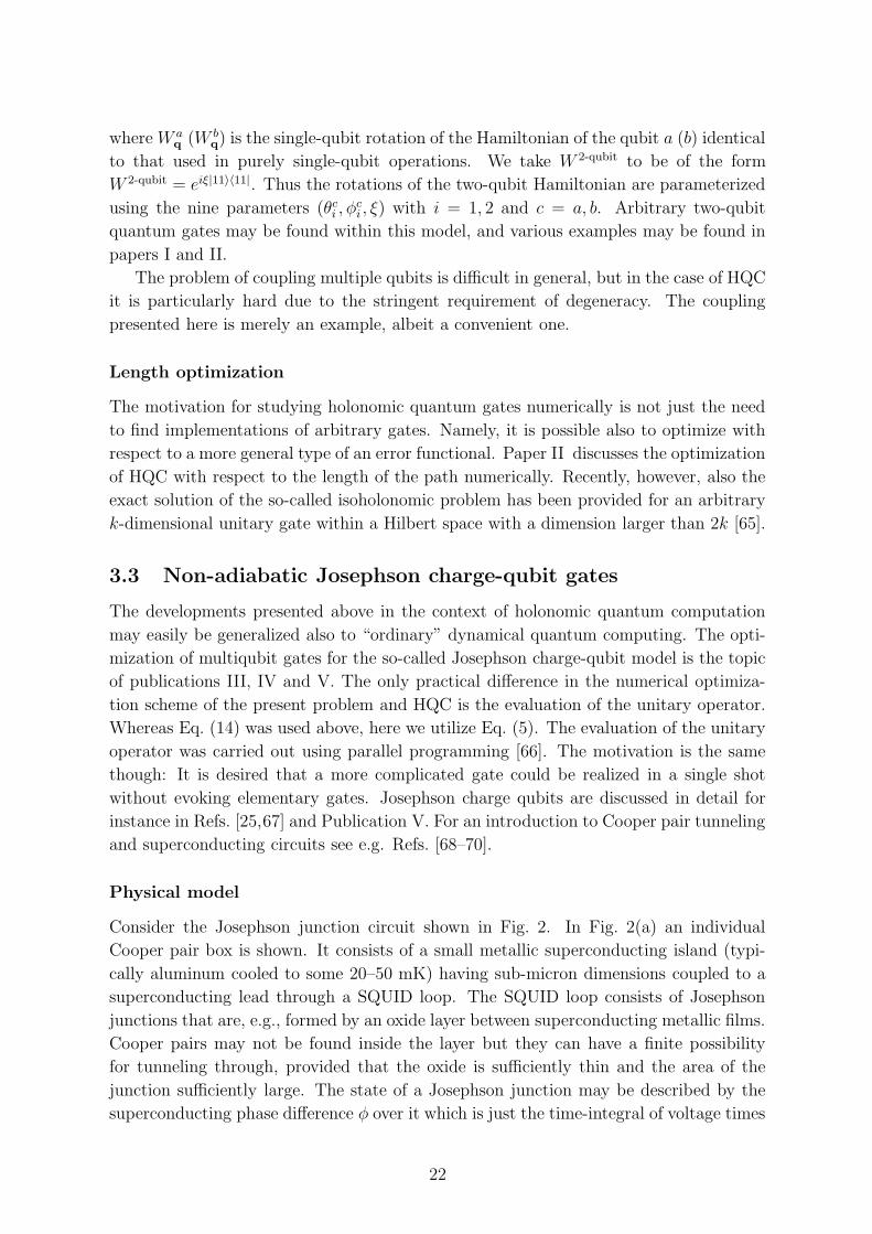
Hamiltonian for M qubits (see Paper V and Ref. [25]) as
Hqb =M∑
i=1
[
−Biz
2σi
z −Bi
x
2σi
x
]
−DM∑
i=1
M∑
j=i+1
BixB
jxσ
iy ⊗ σj
y , (30)
where Biz = EC(1 − 2ni
g), Bix = EJ(Φi) and D = L(πCqb/CJΦ0)
2. We have further
denoted Cqb = CJCg/(CJ + Cg). The index i refers to the ith qubit. Above EJ(Φi) =
EJ cos(πΦi/Φ0) is the effective Josephson energy and nig = CgV
ig is the gate charge. It
is worthwhile to note that this Hamiltonian is only valid near ng = 0.5, i.e. one of the
degeneracy points and if EJ � EC. A particularly convenient property of Eq. (30) is
that the entire Hamiltonian may be set equal to zero, thereby stopping all temporal
evolution. Note that if any two qubits have a non-vanishing tunneling amplitude, they
will be automatically coupled. It is easy to construct any single-qubit gate within this
model on qubit j by setting Bix = Bi
z = 0 for i 6= j and by manipulating Bjx and Bj
z,
see Paper V. Using arbitrary one-qubit operations along with almost any nontrivial two-
qubit gate [46] one may construct any multiqubit operation. This would not, however,
by any means lead to an optimal implementation.
Optimization
In Publication III, the general problem of finding multiqubit gates for the present Hamil-
tonian is considered. The concept is further developed in Publication IV where particular
attention is paid to accelerating algorithms using three-qubit gates. Paper V considers,
as an example, the execution of Shor’s algorithm on Josephson charge qubits using the
optimization method. Just like within HQC, it is possible to associate a loop in the
parameter space with every unitary operation. The parameter vector for a k-qubit op-
eration now assumes the form
q(t) =[B1
z (t) . . . Bkz (t) B1
x(t) . . . Bkx(t)
]T. (31)
We may take the origin, where Hqb = 0, as the starting point for all quantum-control
operations. Then, exactly like in the case of HQC, we may assume that the operations
are polygons in the parameter space. Only now the natural parameterization for loops
is given by time, and also the speed at which the loops are traversed of course matters.
However, we may fix the duration of each edge of the polygon and thus a polygon for k
qubits and with l + 1 vertices has 2l × k degrees of freedom. It is reasonable to require
24

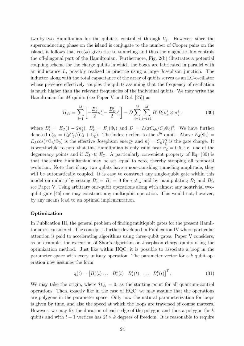
Figure 3. Illustration of the strength of the method in the case of the
Fredkin gate. In (a) and (c), the quantum-circuit notation (see text) for
the single-shot and decomposed Fredkin gate is shown. Subfigures (b) and
(d) show the corresponding parameter pulses. The solid line represents
Biz while the dashed line represents B i
x. The resulting direct three-qubit
implementation is in this case almost three times faster.
that 2lk ≥ 22k − 1 in order to achieve1 the whole SU(2k). The gates are again found by
minimizing f(γ) but now the evaluation of Uγ is carried out by discretizing the loop γ
into a finite set of points γ1, . . . , γn (typically n = 102–104) in the 2k-dimensional space
and since the total time is fixed, we also can fix the time difference ∆t between the points
and write
Uγ ≈ exp(−iHqb(γn)∆t) . . . exp(−iHqb(γ1)∆t). (32)
It is easy to see from the above expression that one can readily divide the evaluation of
the unitary operation into smaller sections of the full loop γ and delegate each subtask
to a separate processor. Thus the evaluation of Uγ is almost trivially parallelized, which
allows for very efficient optimization. In the case of three-qubit gates, 13 processors were
used such that one processor was the master taking care of the optimization routine and
the multiplication of the intermediate results was handled by the slaves consisting of the
12 other processors. The length of each linear edge is fixed to one unit and also D = 1
as well as ~ = 1. The three-qubit gates require 12 edges and the two-qubit gates call for
5 edges. The results are applicable independent of the sample parameters since rescaling
D is possible by simultaneously scaling energy and time.
Figure 3 (Fig. 2 of Paper IV) contains an illustration of the strength of the present
1We cannot achieve U(2k) with the present Hamiltonian since it has been chosen to be traceless, but
the global phase is meaningless.
25
scenario; instead of using the two-qubit gate decomposition of Fig. 3(c) and Fig. 3(d),
in which the realization of individual gates has already been optimized, one may search
for a minimum of f(γ) directly for the whole so-called three-qubit Toffoli gate (see e.g.
Ref. [2]). In Fig. 3 as well as in Publications III–V the so-called quantum-circuit notation
is used. In this notation, time runs from the left to the right and the horizontal lines
represent the history of actions on a particular qubit. In Fig. 3, the qubits are labeled
1, 2 and 3 from top to bottom. A black circle is used to indicate a controlled operation.
In Fig. 3(a), for instance, the notation means that a SWAP (denoted by two crosses)
is performed between the quantum states of qubits 2 and 3 if the state of the qubit
1 is |1〉. Otherwise nothing is done. This is in fact the definition of the Toffoli gate.
In Fig. 3(c), on the other hand, a sequence of seven operations performing the Toffoli
gate in seven substeps is illustrated. The first (leftmost) operation is a controlled-NOT
(CNOT) which flips the qubit 2 iff the qubit 3 is |1〉. The controlled-V operation means
that the operation V =√σx is carried out iff the control qubit is |1〉. Furthermore,
the star in Fig. 3(c) stands for a Hermitean conjugate. A matrix representation can of
course be used for any gates provided that an ordering of the subsystems, i.e. the vector
presentation, has been fixed, but the quantum circuit notation is in many ways much
more informative. For more on this notation see e.g. Ref. [2].
It should be clear from Fig. 3 why the direct implementation is superior. Instead of
allowing one qubit to be idle (parameters Bix and Bi
z set to zero) we can operate on all
the three qubits simultaneously. The resulting single-shot pulse sequence is almost three
times faster than the decomposed version. More examples of optimized gates may be
found in Publications III–V.
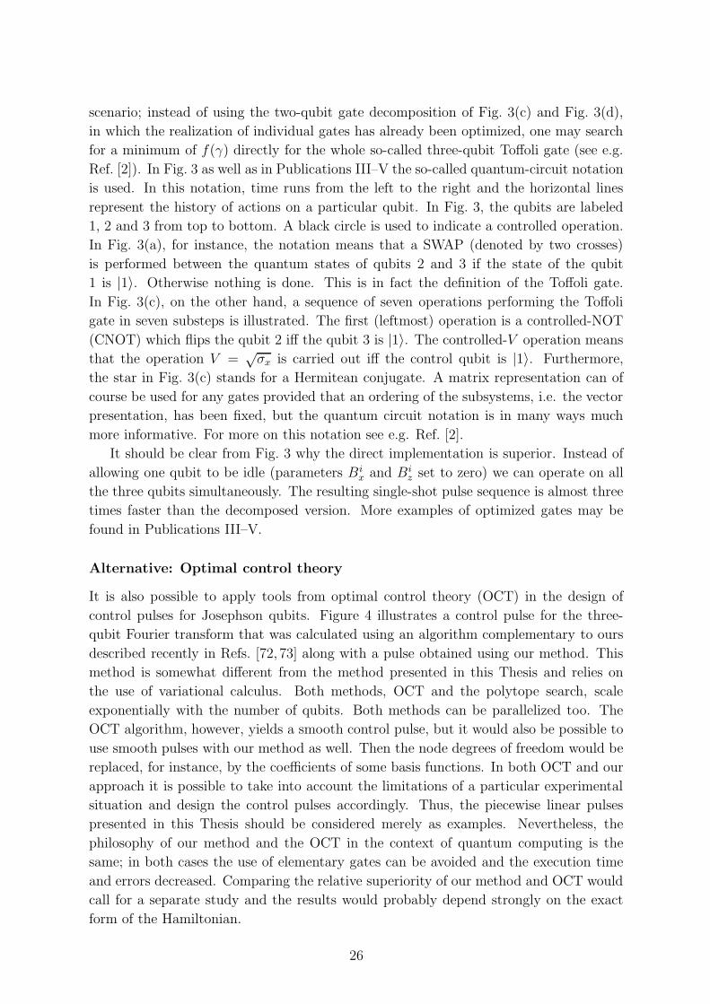
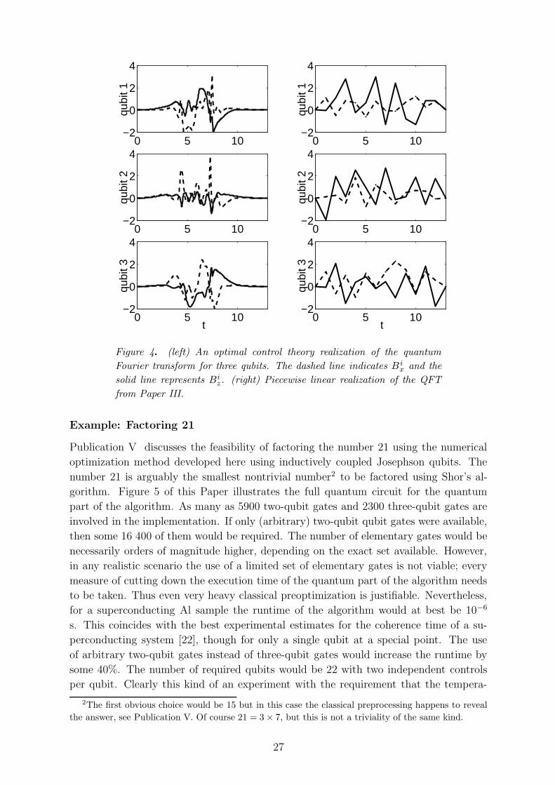
Alternative: Optimal control theory
It is also possible to apply tools from optimal control theory (OCT) in the design of
control pulses for Josephson qubits. Figure 4 illustrates a control pulse for the three-
qubit Fourier transform that was calculated using an algorithm complementary to ours
described recently in Refs. [72, 73] along with a pulse obtained using our method. This
method is somewhat different from the method presented in this Thesis and relies on
the use of variational calculus. Both methods, OCT and the polytope search, scale
exponentially with the number of qubits. Both methods can be parallelized too. The
OCT algorithm, however, yields a smooth control pulse, but it would also be possible to
use smooth pulses with our method as well. Then the node degrees of freedom would be
replaced, for instance, by the coefficients of some basis functions. In both OCT and our
approach it is possible to take into account the limitations of a particular experimental
situation and design the control pulses accordingly. Thus, the piecewise linear pulses
presented in this Thesis should be considered merely as examples. Nevertheless, the
philosophy of our method and the OCT in the context of quantum computing is the
same; in both cases the use of elementary gates can be avoided and the execution time
and errors decreased. Comparing the relative superiority of our method and OCT would
call for a separate study and the results would probably depend strongly on the exact
form of the Hamiltonian.
26
0 5 10−2
0
2
4
qubi
t 1
0 5 10−2
0
2
4
qubi
t 2
0 5 10−2
0
2
4
qubi
t 3
t
0 5 10−2
0
2
4
qubi
t 1
0 5 10−2
0
2
4
qubi
t 2
0 5 10−2
0
2
4
qubi
t 3
t
Figure 4. (left) An optimal control theory realization of the quantum
Fourier transform for three qubits. The dashed line indicates B ix and the
solid line represents Biz. (right) Piecewise linear realization of the QFT
from Paper III.
Example: Factoring 21
Publication V discusses the feasibility of factoring the number 21 using the numerical
optimization method developed here using inductively coupled Josephson qubits. The
number 21 is arguably the smallest nontrivial number2 to be factored using Shor’s al-
gorithm. Figure 5 of this Paper illustrates the full quantum circuit for the quantum
part of the algorithm. As many as 5900 two-qubit gates and 2300 three-qubit gates are
involved in the implementation. If only (arbitrary) two-qubit qubit gates were available,
then some 16 400 of them would be required. The number of elementary gates would be
necessarily orders of magnitude higher, depending on the exact set available. However,
in any realistic scenario the use of a limited set of elementary gates is not viable; every
measure of cutting down the execution time of the quantum part of the algorithm needs
to be taken. Thus even very heavy classical preoptimization is justifiable. Nevertheless,
for a superconducting Al sample the runtime of the algorithm would at best be 10−6
s. This coincides with the best experimental estimates for the coherence time of a su-
perconducting system [22], though for only a single qubit at a special point. The use
of arbitrary two-qubit gates instead of three-qubit gates would increase the runtime by
some 40%. The number of required qubits would be 22 with two independent controls
per qubit. Clearly this kind of an experiment with the requirement that the tempera-
2The first obvious choice would be 15 but in this case the classical preprocessing happens to reveal
the answer, see Publication V. Of course 21 = 3 × 7, but this is not a triviality of the same kind.
27

ture of the environment be around tens of mK is not easy and would probably require
dedicated low-temperature control circuitry, such as rapid single flux quantum (RSFQ)
logic [74,75]. Otherwise at least 44 RF-lines and very complicated pulse generators would
be mandatory. Despite the difficulties, factoring 21 on superconducting qubits should
be possible with very careful design.
Using a scaling argument we may also comment on the factoring of numbers large
enough to break the RSA cryptosystem in the absence of any active coherence preser-
vation method, such as error correction [2, 76]. For instance, breaking the 512-bit RSA
would require thousands of qubits and since the runtime scales at best as n3 log n, where
n is the number of bits it takes to represent the number to be factored, we can argue
based on the estimates given above that tens of seconds of decoherence time is necessary.
The number of independent high-frequency controls would be thousands. Clearly a scal-
able implementation of a superconducting quantum computer is extremely challenging
and far in the future. However, many applications rely on very similar ideas and these
are quite reachable even today. One such application is considered in the next Section.
28

4 Cooper Pair Pumping
In this Section we consider an application of Berry’s [31] Abelian geometrical phase
to Cooper pair pumping using mesoscopic Josephson junctions. Particular attention is
paid to the so-called Cooper pair “sluice” introduced in Paper VI. The idea of operation
and the techniques used are very similar to the control of Josephson charge qubits.
Actually, a Cooper pair “sluice” in a proper environment could serve as a qubit, since the
Hamiltonian presented below offers more than enough possibilities for control. Mastering
the flux and voltage control of only a few superconducting qubits, which is being pursued
by many groups worldwide, does not necessarily have immediate practical impact in
the field of quantum computing. However, spin-offs such the “sluice” may find uses,
e.g., in metrology. Some differences between Cooper pair pumping and superconducting
qubits exist, though. For instance, superpositions of energetically different states are not
pursued and the basic control pulse (pumping cycle) is applied repetitively in contrast
to single-shot quantum gates.
As to charge pumps in general, a seven-junction single-electron pump [30] with cur-
rents on the order of pA has been demonstrated to be usable as a capacitance stan-
dard [77], but the realization of the so-called quantum metrological triangle [78] would
require currents on the order of nA. This is beyond single-electron pumps, but Cooper
pair pumps could potentially yield currents accurately in the nA range. The use of Sur-
face Acoustic Waves (SAW) to pump electrons is being studied actively as an alternative
to ordinary electron pumps, see e.g. Ref. [79]. The engineering of the electromagnetic
environment of both electron pumps [80] as well as Cooper pair devices [81] using on-chip
resistors has been considered in order to achieve a frequency-locked current source. No
metrological Cooper pair pump has been realized yet.
The considered form of the temporal control is not found numerically but rather
using analytic physical arguments. In Subsection 4.1, the relationship between Cooper
pair pumping and Berry’s phase is discussed. Subsection 4.2 discusses the theory of the
“sluice”. Subsection 4.3, based on the experiments of Publication VII, is the highlight
of the present Section.
4.1 Adiabatic Cooper pair pumping and Berry’s phase
An adiabatic Cooper pair pump is a chain of Josephson junctions with at least two
tunable parameters. For instance the first measured pump of Geerligs et al. [26] had
three Josephson junctions in a chain and two voltage gates coupled to the islands in
between. A similar structure was also recently measured by Toppari et al. [82]. However,
longer chains, including the seven-junction Cooper pair pump of Aumentado et al. [83],
have been studied as well. The requirement that at least two parameters are needed is
due to the fact that the pumping effect is attributable to a loop in the parameter space.
We will make the connection between the pumped charge and Berry’s phase clear in
simple terms. For a more formal derivation see Ref. [84].
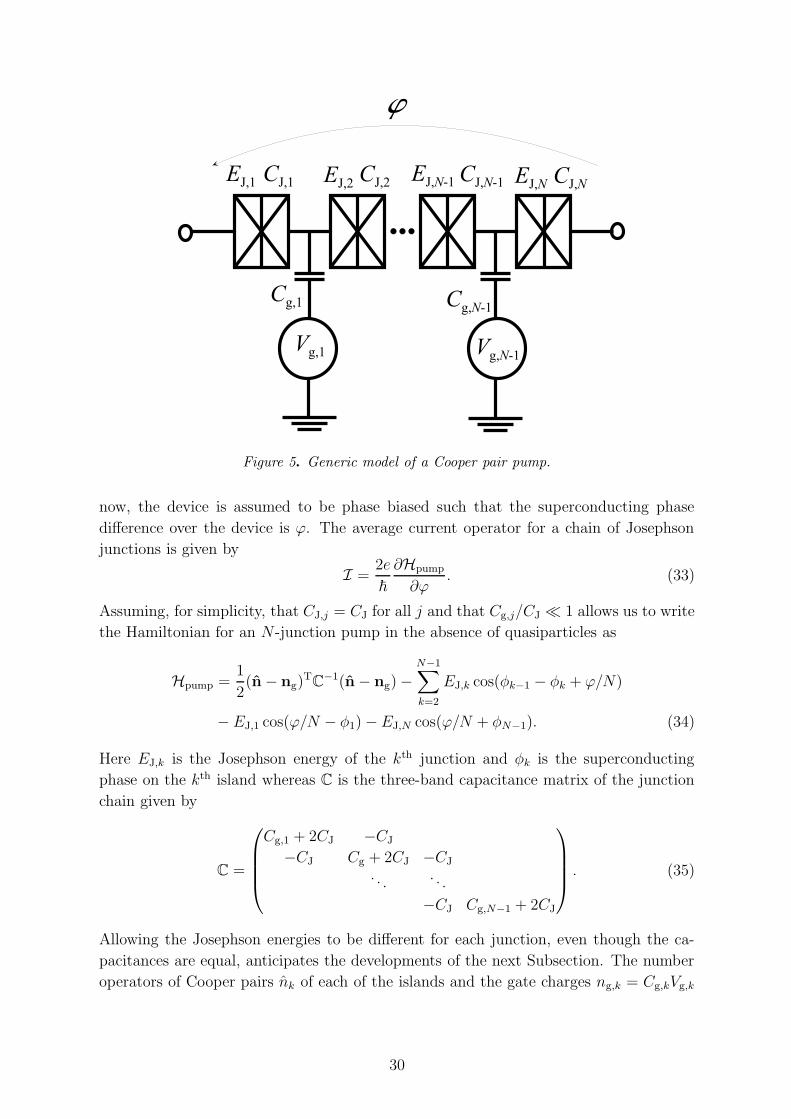
The Cooper pair pump shown in Fig. 5 serves as a generic model that encompasses
both the traditional gate-controlled pumps and the flux-assisted pump studied here. For
29
V g , 1 V g , N - 1
C g , 1 C g , N - 1
wE J , 1 E J , 2 E J , N C J , NC J , 1 C J , 2 C J , N - 1E J , N - 1
Figure 5. Generic model of a Cooper pair pump.
now, the device is assumed to be phase biased such that the superconducting phase
difference over the device is ϕ. The average current operator for a chain of Josephson
junctions is given by
I =2e
~
∂Hpump
∂ϕ. (33)
Assuming, for simplicity, that CJ,j = CJ for all j and that Cg,j/CJ � 1 allows us to write
the Hamiltonian for an N -junction pump in the absence of quasiparticles as
Hpump =1
2(n − ng)
TC
−1(n − ng) −N−1∑
k=2
EJ,k cos(φk−1 − φk + ϕ/N)
− EJ,1 cos(ϕ/N − φ1) − EJ,N cos(ϕ/N + φN−1). (34)
Here EJ,k is the Josephson energy of the kth junction and φk is the superconducting
phase on the kth island whereas C is the three-band capacitance matrix of the junction
chain given by
C =
Cg,1 + 2CJ −CJ
−CJ Cg + 2CJ −CJ
. . .. . .
−CJ Cg,N−1 + 2CJ
. (35)
Allowing the Josephson energies to be different for each junction, even though the ca-
pacitances are equal, anticipates the developments of the next Subsection. The number
operators of Cooper pairs nk of each of the islands and the gate charges ng,k = Cg,kVg,k
30

are contained in n and ng, that is
n =
n1
...
nN
and ng =
ng,1
...
ng,N
. (36)
Now let us assume that the parameters of the system denoted collectively by q(t) are
tuned adiabatically around a cycle γ in the parameter space over the time t ∈ [0, tcycle]
and that the ground state is non-degenerate. What the parameters are is not important
for the derivation. Clearly, the total charge that passes through the device is
Qtot =
∫ tcycle
0
〈ψ(t)|I|ψ(t)〉dt, (37)
where |ψ(t)〉 is the state vector of the pump at the time t. Using Eq. (9) of Section 2
with g = 1 as well as Eq. (11) allows us to write the state of the pump at time t as
|ψ(t)〉 = eiθ(t)|0;q(t)〉 (38)
due to the adiabaticity assumption. Here |0;q〉 is the ground-state vector which depends
on the control-parameter vector q. The phase θ(t) has two contributions, namely the
dynamical phase
θdyn(t) = −1
~
∫ t
0
〈0;q(τ)|Hpump|0;q(τ)〉dτ (39)
and the geometrical phase
θgeom(t) = i
∫ t
0
〈0;q(τ)| ddτ
|0;q(τ)〉dτ = i
∫q(t)
q(0)
〈0;q|∇q|0;q〉 · dq. (40)
At time tcycle it holds in particular that
θBerry ≡ θgeom(tcycle) = i
∮
γ
〈0;q|∇q|0;q〉 · dq (41)
since at this instant the cycle is full. Now, it is possible to rewrite the integrand in
Eq. (37) as
〈ψ(t)|I|ψ(t)〉 = 〈ψ(t)|2e~
∂Hpump
∂ϕ|ψ(t)〉 =
2e
~〈ψ(t)|
[∂
∂ϕ,Hpump
]
|ψ(t)〉. (42)
Owing to the Schrodinger equation, we may further write
〈ψ(t)|I|ψ(t)〉 = 2eid
dt
(
〈ψ(t)| ∂∂ϕ
|ψ(t)〉)
. (43)
On the other hand
〈ψ(t)| ∂∂ϕ
|ψ(t)〉 = 〈0;q(t)|e−iθ(t) ∂
∂ϕeiθ(t)|0;q(t)〉
= i∂θ(t)
∂ϕ〈0;q(t)|0;q(t)〉+ 〈0;q(t)| ∂
∂ϕ|0;q(t)〉
= i∂θ(t)
∂ϕ+ 〈0;q(t)| ∂
∂ϕ|0;q(t)〉. (44)
31

The pumped charge is thus (use q(0) = q(tcycle) and θ(0) = 0)
Qtot = −2e
∫ tcycle
0
d
dt
(∂θ(t)
∂ϕ
)
dt+
∫ tcycle
0
2eid
dt〈0;q(t)| ∂
∂ϕ|0;q(t)〉dt
︸ ︷︷ ︸
=0
= −2e∂
∂ϕ(θdyn(tcycle) + θBerry) . (45)
The total charge transferred is −2e times the derivative of the phase accumulated over
one cycle with respect to the global superconducting phase difference. The first part, or
the dynamical contribution is
Qs = −2e∂
∂ϕ(θdyn(tcycle)) =
2e
~
∂
∂ϕ
∫ tcycle
0
〈0;q(t)|Hpump|0;q(t)〉dt
=
∫ tcycle
0
〈0;q(t)|I|0;q(t)〉dt (46)
which is just the “classical” Josephson supercurrent. In pumping applications one tries
to suppress the supercurrent altogether. The second contribution is the more nontrivial
pumped charge
Qp = −2e∂
∂ϕ(θBerry) = −2e
∂
∂ϕ
∮
γ
i〈0;q(t)|∇q|0;q(t)〉 · dq (47)
and as may be seen, this is in close connection with Berry’s phase. Thus pumping
Cooper pairs may, very naturally, be seen as an observable manifestation of Berry’s
phase. It is remarkable that Berry’s phase of a nondegenerate ground state has observable
consequences while for instance in quantum computing either degeneracy (holonomy) or
superpositions of energetically different states are required for observable consequences.
In quantum computing the loop γ applies a logical operation whereas here it pumps
charge.
It is possible to derive from Eq. (47) a more elaborate expression for the pumped
charge appearing often in literature. We may write
Qp = 2~ Im
[∞∑
m=1
∮
γ
〈0;q|I|m;q〉εq,0 − εq,m
〈m;q|∇q|0;q〉 · dq]
, (48)
where |m;q〉 is the mth energy eigenstate and εq,m is its energy. This is the form found
first in Ref. [27] and the equivalence between Eq. (48) and Eq. (47) is demonstrated in
Ref. [84].
4.2 Cooper pair “sluice”
The expressions derived above for the pumped charge are quite general and the exact
nature of the tunable parameters has not yet been specified. Traditionally, charge pump-
ing through a chain of Josephson junctions is achieved via cyclically manipulating gate
voltages in such a manner that the state of the system propagates adiabatically through
32

0 0 . 1 0 . 2 0 . 3 0 . 4 0 . 5 0 . 6 0 . 7 0 . 8 0 . 9 10
0 . 5
1
n g
0 0 . 1 0 . 2 0 . 3 0 . 4 0 . 5 0 . 6 0 . 7 0 . 8 0 . 9 10
0 . 5
1
E J r / E J ma
x0 0 . 1 0 . 2 0 . 3 0 . 4 0 . 5 0 . 6 0 . 7 0 . 8 0 . 9 10
0 . 5
1
t / t c y c l e E
J l / E J ma
x
n = 0 n = 0n = 1- 2 e - 2 e(a) (b)
Figure 6. (a) Schematic of the Cooper pair “sluice”. (b) Pulse sequence
for pumping a single Cooper pair through the sluice. The exact form of
the pulses is not crucial as long as synchronization is maintained.
a series of near-eigenstates of charge. For instance, in the three-junction Cooper pair
pump [26, 27, 82] one may denote by (Q1, Q2) the eigenstate of charge with Q1 resid-
ing on island 1 and Q2 residing on island 2. Then the gate voltages are manipulated
adiabatically such that the cycle (Q1, Q2) : (0, 0) → (0, 2e) → (2e, 0) → (0, 0) is al-
most achieved. However, due to the non-vanishing Josephson coupling, the eigenstate
of energy is not an eigenstate of charge. It is impossible to decrease the Josephson en-
ergies of the junctions indefinitely without sacrificing the adiabaticity since the smallest
excitation energy is proportional to EJ. Stated otherwise, there is a tradeoff between
accuracy and adiabaticity. From the point of view of adiabaticity it would be beneficial
to increase EJ indefinitely, but in the adiabatic limit there is an error in the pumped
charge proportional to EJ such that it would be desirable to make EJ small. These two
seemingly contradicting requirements are the reason for considering tunable Josephson
junctions, i.e. SQUIDs.
The Cooper pair sluice is a single-island Cooper pair pump. It was introduced and
analyzed theoretically in Publication VI. A single island and a single gate voltage are
sufficient due to the fact that also the couplings are controlled. A schematic of the device
is shown in Fig. 6(a). The Hamiltonian of a homogeneous Cooper pair sluice is explicitly
Hsluice =EC(n− ng)2 − Er
J
(
πΦr
Φ0
)
cos(φ+ ϕ/2)
− E lJ
(
πΦl
Φ0
)
cos(ϕ/2 − φ). (49)
Here φ is the phase on the island and n is the number operator for Cooper pairs.
They obey the commutation relation [n, φ] = i. The charging energy is given by
33

EC = 2e2/(2CJ +Cg) and the gate charge is ng = CgVg/2e. Furthermore, E lJ and Er
J are
the effective Josephson energies of the left and right SQUIDs, respectively, which we as-
sume may in principle be set to zero. The flux through the left (right) junction is denoted
by Φl (Φr). The parameter vector q for the present device is given by q = (ng, ErJ, E
lJ)
T.
The pumping of charge is achieved via manipulating the parameters q adiabatically such
that at certain instants the ground state is ideally also exactly an eigenstate of charge.
This may be achieved by setting the Josephson couplings to zero. A typical pumping
cycle is shown in Fig. 6(b).
For instance, we may assume that initially the ground state is an eigenstate with zero
Cooper pairs which we attain e.g. with E lJ = 0, Er
J = 0 and ng = 0. Then keeping ErJ = 0
and tuning ng from zero to one and simultaneously opening the left SQUID (first vertical
dashed line in Fig. 6(b)) and closing it again (second dashed line) adiabatically increases
the number of Cooper pairs on the island by one. Namely, the ground state is after the
manipulation still an eigenstate of charge but with one more pair and we have assumed
that the system stays at its ground state. The extra Cooper pair must have tunneled
through the left SQUID since the right one was closed altogether. Ramping ng from one
again back to zero while simultaneously opening (third dashed line) and closing the right
SQUID clearly takes us to where we began: The island again has zero Cooper pairs. This
time the charge must have flown through the left SQUID. In conclusion, this cycle leads
to a pumping of exactly one Cooper pair through the device. Repeating the cycle at
the frequency f leads to a DC current I = 2ef . Note that the above logic immediately
generalizes to the pumping of m Cooper pairs by working between ng = 0 and ng = m
yielding I = 2emf . The crucial assumption is that the temporal evolution is adiabatic.
It is worth pointing out explicitly that the above cycle maintains the non-degeneracy of
the ground state such that the system indeed is protected against excitations to higher
levels.
The imperfections of the sluice have been analyzed in Publication VI. To this end,
the sluice was simulated using numerical integration of the Schrodinger equation. This
was carried out using the loop shown in Fig. 6(b) as a basis for the time dependence
of the Hamiltonian Hsluice. Then, just like in the case of quantum algorithms, the time
axis was split to a discrete set of points (106 or more) that were a distance ∆t apart
and the Hamiltonian was considered piecewise constant in time. The Hilbert space was
truncated to some 10–30 charge states depending on the value of m considered. The
state vectors were propagated using
|ψ(t+ ∆t)〉 ≈ exp(−iHsluice(t+ ∆t/2)∆t/~)|ψ(t)〉. (50)
The quantity of interest, QP in Eq. (37) was evaluated simply using the trapezoidal rule.
Note that the current operator also has a time dependence. The discretization was made
fine enough such that increasing the number of points did not change the result.
It was found that the pumping of individual Cooper pairs with an accuracy of 10−7
should be possible at currents of some 10 pA. However, increasing m to m = 10, would
allow pumping of 0.1 nA with the same accuracy. These estimates only take into ac-
count the finite operating frequency. The optimal value of m is not known. It was
34

also found that with sufficient phase averaging errors should not increase. Namely, the
leakage supercurrent is proportional to sinϕ while the error in the pumped charge QP
is proportional to cosϕ. The average of both of these under a perfect voltage bias V is
clearly zero since then ϕ = 2eV t/~.
4.3 Experiments on the “sluice”
Paper VII describes the experiments demonstrating the pumping of Cooper pairs uti-
lizing the idea described above. Figure 7 shows scanning electron micrographs (SEM) of
the measured sample as well as a schematic of the measurement setup. The sample was
fabricated using standard e-beam lithography and two-angle shadow evaporation. The
steps of the fabrication process included spinning a two-layer PMMA/MAA (polymethyl
methacrylate/methacrylic acid) and PMMA resist on top of a silicon wafer, drawing
the pattern of the device using an electron beam, developing the resist in two different
solvents (first in a mixture of 25% MIBK (methyl isobutyl ketone) and 75% IPA (iso-
propanol) and then in pure IPA) to get an “undercut” and finally evaporating aluminum
from two different angles in vacuum with an oxidization step between the layers. The
Josephson junctions are thus realized as an Al-AlOx-Al sandwich. The thicknesses of
the Al layers were 30 nm and 50 nm while the thickness of the oxide is a few nm. The
extra aluminum was removed in the lift-off done by dipping the chip in acetone. The
two different layers can be seen as “shadows” in Fig. 7(b). The sample was then at-
tached to the sample holder of a He3- He4 dilution cryostat with a base temperature
of 20 mK and electrically connected using Al wire bonds. The two ends of the device
were bonded to DC lines in a four-point configuration as shown in Fig. 7(c) while the
two input coils and the gate were connected to RF lines with bandwidth up to tens of
GHz. The measurement electronics along with the arbitrary waveform generators used
for realizing the flux and voltage control were connected to a PC. Matlab scripts and
Matlab’s Data Acquisition Toolbox were used to carry out the measurement.
The sample parameters were Cg ≈ 0.2 fF, EC/kB ≈ 1 K and EJ/kB ≈ 0.5 K. The
estimate of the gate capacitance is based on gate periodicity measurements, that of the
charging energy on the measurement of the normal-state conductance at 4.2 K [85] while
the estimate of EJ is based on the normal-state resistance and the Ambegaokar-Baratoff
formula [71], i.e., EJ = h∆BCS/8e2RT. For the arrangement of the flux pulsing it is
important to know the mutual inductances between the input coils and the SQUIDs.
The SQUIDs were intentionally designed to have large extensions to get better coupling.
The mutual inductances were measured by sweeping the DC current in the two input
coils at constant bias voltage and by measuring the current. This allows one to design
the flux pulses with proper compensations for the cross-talk, see Publication VII. The
relative phases were optimized by sweeping them and maximizing the current. Since we
were using commercial waveform generators, we were forced to use frequencies on the
order of a few MHz. Luckily, though, we could compensate for the low frequency by
increasing the number of pumped charges m, i.e. the gate amplitude.
The measurement of the full current-voltage characteristics was carried out with the
35

Figure 7. (a) Scanning electron micrograph of the Cooper pair “sluice”.
The input coils are seen topmost and lowest in the picture while the gate
extends to the right. The current flows between the two electrodes on the
left. (b) Close-up of the island. The Josephson junctions are the four
lighter-shade spots formed in the overlap of the two shadows. (c) Mea-
surement setup.
pumping signal being applied underneath. It was found that despite the manipulation of
the Josephson energies, leakage current unfortunately also existed. However, since it was
possible to change the direction of the current by shifting the phase of the gate through
180 degrees, it is possible to extract the pumped current from this measurement. Namely,
subtracting the IVs with the pumping applied forward and backward from each other
should leave us with twice the pumped current. Figure 8 shows full IVs at 3 MHz for
different gate amplitudes with pumping in both directions along with the aforementioned
differences ∆I vs. voltage. It is seen that the difference in the current nicely obeys the
expected pumping behavior. In order to serve as a practical current pump the leakage
should be taken care of, e.g., by improved voltage biasing and/or improving the closing
of the SQUIDs.
The most convincing evidence of the pumping along with the fact that the above
phase shift procedure works, is found by gradually increasing the gate amplitude and then
measuring the current at a constant voltage bias. The results are shown in Fig. 9. The
quantity that we studied was ∆I in this measurement too. The amplitude was increased
such that the low level of the gate V log was fixed and the high level V hi
g was swept. This
36

- 1 0 0 - 5 0 0 5 0 1 0 0- 5 0
0
5 0
V m e a s ( m V )
I (pA)
( a )
- 1 0 0 - 5 0 0 5 0 1 0 00
2 0
4 0
6 0
V m e a s ( m V )
DI (pA
)
( b )
Figure 8. (a) IVs for pumping forward (solid) and backward (dashed).
Here m ranges between 4 and 34. (b) Differences ∆I in the IVs (see text).
Horizontal dotted lines indicate the expected levels of current. Here Vmeas
is the measured value of voltage.
should result in 2e-periodic staircase in the pumped current with the step heights3 equal
to 4ef . However, due to quasiparticle poisoning faster than the measurement time scale
but slower than the pumping, the measured behavior was e-periodic with 2ef steps.
This is interpreted to be because we actually measure the average of two 2e-periodic
staircases shifted by e with respect to each other. Figure 9(b) also shows the high gate
amplitude behavior of ∆I and it is seen that up to amplitudes of 10e the agreement with
the expected behavior is good. Fig. 9(c) illustrates the least-squares fitted slopes to the
linear regime of Figs. 9(a–b). The agreement with theory is seen to be good with a few
percent error.
To conclude, we have demonstrated in practice the original idea of Publication VI for
pumping Cooper pairs with tunable Josephson junctions, i.e. SQUIDs. The experimen-
tal evidence is convincing enough to show that the idea for pumping works, although
several non-idealities still exist. Possible solutions for cutting down the leakage include
fabricating an on-chip capacitor much larger than the junction capacitance parallel with
the pump, considering a more complicated design for the SQUIDs (see Fig. 1(b) of Pub-
lication VI) and maybe even using a longer array. Lengthening the array would, though,
inevitably complicate the control. The capacitance, however, would better conserve the
energy of the pump since then the so-called P(E)-curve would be peaked close to the zero
of energy, see e.g. Ref. [70]. The quasiparticle poisoning is not necessarily a problem even
from the application point of view, if the quasiparticle current is small enough. Namely,
our measurements indicate that the net quasiparticle flow is negligible but, instead, the
quasiparticles jump randomly on and off the island with no preferred direction. That
is, the flow of current is mostly due to Cooper pairs. The quasiparticles in the present
measurement are thus probably of the non-equilibrium type reported in Ref. [86]. There
the reported time scale of quasiparticle poisoning for a superconducting SET was 10 µs.
In Ref. [87] the relevant time-scale was 10−2 s but in a somewhat different setup. These
figures support our time scale argument, since the integration time for our measurement
3Recall that ∆I should be twice the pumped current.
37

0 1 2 3 4 5012345
0 1 0 2 0 3 0 4 0 5 00
2 0
4 0
6 0
0 2 4 6 8 1 002468
C g V g h i / e
( a )
DI (pA
)
( b )
DI (pA
)
1 M H z2 M H z3 M H z4 M H z ( c )
f ( M H z )DI
/ (2C gV
ghi ) (MH
z)
C g V g h i / e
Figure 9. (a) Difference ∆I in the current for forward and backward
pumping at 2.5 MHz against the high level of the gate signal V hig with the
low level at zero. The dashed lines are drawn at 2ef intervals. (b) Large
gate amplitude behavior of ∆I at a few frequencies. The dashed lines
show the expected gate dependence, i.e. their slope is 2ef . The curves are
offset for clarity. (c) Fitted slopes to the data of the previous plots up to
VgCg/e = 10 are shown by circles. The solid line indicates the expected
behavior. The voltage bias point was around 10 µV in all the above plots.
was on the order of 0.1 s and the pumping time smaller than 1 µs. We could not, how-
ever, experimentally determine the characteristic time for quasiparticles in the present
setup.
38

5 Conclusions
In this Overview we have discussed different aspects of the controlled evolution of
quantum systems, both geometrical and dynamical. Particular attention was paid to
nanoscale Josephson junction circuits. The two applications that were considered in
detail included quantum computing and quantum charge pumping. Let us briefly sum-
marize the conclusion of the Publications included in this Thesis:
In Publications I–II, a realization independent numerical method of finding arbitrary
holonomic quantum gates was studied. It was shown that holonomy loops realizing
any one and two-qubit unitary operation for the studied three-state model can be found
easily. Moreover, it was shown that the length of the loop could be reduced by numerical
optimization.
In Publications III–V, the optimization method was generalized to dynamical quan-
tum computing. The physical system studied was the inductively coupled Josephson
charge qubit array, although the method could easily be generalized to other systems.
The algorithm was parallelized and shown to be capable of finding single-shot realiza-
tions for up to three-qubit gates. Publication III introduced the method while Publica-
tion IV concentrated on accelerating quantum algorithms using three-qubit gates. The
more extended Publication V discussed the requirements of performing Shor’s algorithm
on the inductively coupled charge-qubit array. It was found that factoring 21, arguably
the simplest “non-trivial” composite integer, would require 22 qubits and microsecond
coherence times which is on the same order as the best reported coherence times in
superconducting circuits. However, it was found, that breaking for instance the 512-bit
RSA would require thousands of qubits working co-operatively and tens of seconds in
terms of coherence time. All the estimates were based on the assumption that arbitrary
three-qubit gates are available in single-shot form. The use of elementary gates would
prolong the runtime severely. The conclusion regarding Publications I-V is that even
though no change in the complexity of the algorithm is obtained via numerical opti-
mization, the stringent limits set by short decoherence times makes it well worthwhile
to try and reduce the runtime even by a numerical factor. Optimization may well result
in cutting down the runtime by orders of magnitude opposed to elementary-gate logic
inspired by classical computers.
In Publication VI, an application of Berry’s geometrical phase in a superconducting
circuit was discussed. There a novel Cooper pair pump, the “sluice”, consisting of
just one superconducting island connected to leads via SQUID loops and utilizing both
flux and voltage control was introduced. It was shown that the device can potentially
reach metrological accuracy. In Publication VII, the experimental results of the device
were reported. It was found that the pumped current increases in clear steps with the
increasing gate amplitude and changes direction under a 180-degree phase shift of the
gate, even though quasiparticle poisoning and leakage were present. Many suggestions
for improving the device were given. The “sluice” was found to be a promising candidate
for a practical current pump. The clear benefit of the “sluice” is that it is simple with
just three control parameters and it would allow for higher operating frequencies. One
39

may further argue that solving the practical challenges in its control is much easier than
building even a simple working quantum computer. It could, therefore, find use as a
great test bench for the control techniques of superconducting qubits.
40
References
[1] P. W. Shor, Algorithms for quantum computation: discrete logarithms and factoring,
in Proceedings, 35th Annual Symposium on Foundations of Computer Science, IEEE
Computer Society Press, Los Alamitos, CA, (1994).
[2] M. A. Nielsen and I.L. Chuang, Quantum computation and quantum information,
Cambridge University Press, Cambridge (2000).
[3] M. Hirvensalo, Quantum computing, Springer, Berlin (2001).
[4] J. Gruska, Quantum computing, McGraw–Hill, New York (1999).
[5] A. Galindo and M. A. Martın-Delgado, Information and computation: Classical and
quantum aspects, Rev. Mod. Phys. 74, 347 (2002).
[6] N. Gisin, G. Ribordy, W. Tittel, and H. Zbinden, Quantum cryptography, Rev. Mod.
Phys. 74, 145 (2002).
[7] L. M. K. Vandersypen and I. L. Chuang, NMR techniques for quantum control,
quant-ph/0404064 (2004).
[8] S. A. Rice and M. Zhao, Optimal control of molecular dynamics, Wiley, New York
(2000).
[9] L. M. K. Vandersypen, M. Steffen, G. Breyta, C. S. Yannoni, M. H. Sherwood, and
I.L. Chuang, Experimental realization of Shor’s quantum factoring algorithm using
magnetic resonance, Nature 414, 883 (2001).
[10] A. Shnirman, G. Schon, and Z. Hermon, Quantum meanipulations with small
Josephson junctions, Phys. Rev. Lett. 79, 2371 (1997).
[11] Y. Nakamura, Yu. A. Pashkin, and J. S. Tsai, Coherent control of macroscopic
quantum states in a single-Cooper-pair box, Nature 398, 786 (1999).
[12] Y. Nakamura, Yu. A. Pashkin, and J. S. Tsai, Rabi oscillations in a Josephson-
junction charge two-level system, Phys. Rev. Lett. 87, 246601 (2002).
[13] Y. Nakamura, Yu. A. Pashkin, T. Yamamoto, and J. S. Tsai, Charge echo in a
Cooper-pair box, Phys. Rev. Lett. 88, 047901 (2002).
[14] Yu. A. Pashkin, T. Yamamoto, O. Astafiev, Y. Nakamura, D. V. Averin and J. S.
Tsai, Quantum oscillations in two coupled charge qubits, Nature 421, 823 (2003).
[15] T. Yamamoto, Yu. A. Pashkin, O. Astafiev, Y. Nakamura, and J. S. Tsai, Demon-
stration of conditional gate operation using superconducting charge qubits, Nature
425, 941 (2003).
[16] J. E. Mooij, T. P. Orlando, L. Levitov, L. Tian, C. H. van der Wal, and S. Lloyd,
Josephson persistent-current qubit, Science 285, 1036 (1999).
41

[17] T. P. Orlando, J. E. Mooij, L. Tian, C. H. van der Wal, L. Levitov, S. Lloyd, and J.
J. Mazo, Superconducting persistent-current qubit, Phys. Rev. B 60, 15398 (1999).
[18] C. H. van der Wal, A. C. J. ter Haar, F. K. Wilhelm, R. N. Schouten, C. J. P.
M. Harmans, T. P. Orlando, S. Lloyd, and J. E. Mooij, Quantum superposition of
macroscopic persistent-current states, Science 290, 773 (2000).
[19] I. Chiorescu, Y. Nakamura, C. J. P. M. Harmans, and J. E. Mooij, Coherent quantum
dynamics of a superconducting flux qubit, Science 299, 1869 (2003).
[20] Y. Yu, S. Han, X. Chu, S. Chu, and Z. Wang, Coherent temporal oscillations of
macroscopic quantum states in a Josephson junction, Science 296, 889 (2002).
[21] J. M. Martinis, S. Nam, J. Aumentado, and C. Urbina, Rabi oscillations in a large
Josephson-junction qubit, Phys. Rev. Lett. 89, 117901 (2002).
[22] D. Vion, A. Aassime, A. Cottet, P. Joyez, H. Pothier, C. Urbina, D. Esteve, and M.
H. Devoret, Manipulating the quantum state of an electrical circuit, Science 296,
886 (2002).
[23] J. Claudon, F. Balestro, F. W. J. Hekking and O. Buisson, Coherent oscillations in
a superconducting multi-level quantum system, cond-mat/0405430 (2004).
[24] M. V. Feigel’man, L. B. Ioffe, V. B. Geshkenbein, P. Dayal, and G. Blatter, Super-
conducting tetrahedral quantum bits, Phys. Rev. Lett. 92, 098301 (2004).
[25] Yu. Makhlin, G. Schon, and A. Shnirman, Quantum-state engineering with
Josephson-junction devices, Rev. Mod. Phys. 73, 357 (2001).
[26] L. J. Geerligs, S. M. Verbrugh, P. Hadley, J. E. Mooij, H. Pothier, P. Lafarge,
C. Urbina, D. Esteve, and M. H. Devoret, Single Cooper pair pump, Z. Phys. B:
Condens. Matter 85, 349 (1991).
[27] J. P. Pekola, J. J. Toppari, M. Aunola, M. T. Savolainen, and D. V. Averin, Adiabatic
transport of Cooper pairs in arrays of Josephson junctions, Phys. Rev. B 60, R9931
(1999).
[28] R. Fazio, F. W. J. Hekking, and J. P. Pekola, Measurement of coherent charge
transfer in an adiabatic Cooper-pair pump, Phys. Rev. B 68, 054510 (2003).
[29] P. Zanardi and M. Rasetti, Holonomic quantum computation, Phys. Lett. A. 264,
94–99, 1999.
[30] M. W. Keller, J. M. Martinis, N. M. Zimmerman, and A. H. Steinbach, Accuracy
of electron counting using a 7-junction electron pump, Appl. Phys. Lett. 69, 1804
(1996).
[31] M. Berry, Quantal phase factors accompanying adiabatic changes, Proc. R. Soc.
Lond. A 392, 45 (1984).
42

[32] F. Wilczek and A. Zee, Appearance of gauge structure in simple dynamical systems,
Phys. Rev. Lett. 52, 2111 (1984).
[33] W. H. Zurek, Decoherence, einselection, and the quantum origins of the classical,
Rev. Mod. Phys. 75, 715 (2003).
[34] A. O. Caldeira and A. J. Leggett, Path integral approach to quantum Brownian
motion, Physica A, 121, 587 (1983).
[35] R. W. Simmonds, K. M. Lang, D. A. Hite, D. P. Pappas, and J. M. Martinis, De-
coherence in Josephson qubits from junction resonances, cond-mat/0402470 (2004).
[36] J. M. Martinis, S. Nam, J. Aumentado, K. M. Lang, and C. Urbina, Decoherence
of a superconducting qubit from bias noise, Phys. Rev. B 67, 094510 (2003)
[37] E. Paladino, L. Faoro, G. Falci, and R. Fazio, Decoherence and 1/f noise in Joseph-
son qubits, Phys. Rev. Lett. 88, 228304 (2002).
[38] J. P. Pekola and J. J. Toppari, Decoherence in circuits of small Josephson junctions,
Phys. Rev. B 64, 172509 (2001).
[39] M. J. Storcz and F. K. Wilhelm, Decoherence and gate performance of coupled
solid-state qubits, Phys. Rev. A 67, 042319 (2003).
[40] L. E. Ballentine, Quantum mechanics, World Scientific, Singapore (1998).
[41] A. Zee, Non-Abelian gauge structure in nuclear quadrupole resonance, Phys. Rev. A
38, 1 (1988).
[42] A. Einstein, B. Podolsky, and N. Rosen, Can quantum-mechanical description of
reality be considered complete?, Phys. Rev. 47, 777 (1935).
[43] M. Riebe, H. Haffner, C. F. Roos, W. Hansel, J. Benhelm, G. P. T. Lancaster, T. W.
Korber, C. Becher, F. Schmidt-Kaler, D. F. V. James, and R. Blatt, Deterministic
quantum teleportation with atoms, Nature 429, 734 (2004).
[44] M. D. Barrett, J. Chiaverini, T. Schaetz, J. Britton, W. M. Itano, J. D. Jost, E.
Knill, C. Langer, D. Leibfried, R. Ozeri, and D. J. Wineland, Deterministic quantum
teleportation of atomic qubits, Nature 429, 737 (2004).
[45] L. K. Grover, Quantum mechanics helps in searching for a needle in a haystack,
Phys. Rev. Lett. 79, 325 (1997).
[46] A. Barenco, C. H. Bennett, R. Cleve, D. P. DiVincenzo, N. Margolus, P. Shor, T.
Sleator, J. A. Smolin, and H. Weinfurter, Elementary gates for quantum computa-
tion, Phys. Rev. A 52, 3457 (1995).
[47] J. J. Vartiainen, M. Mottonen, and M. M. Salomaa, Efficient Decomposition of
Quantum Gates, Phys. Rev. Lett. 92, 177902 (2004).
43

[48] M. Mottonen, J. J. Vartiainen, V. Bergholm, and M. M. Salomaa, Universal quan-
tum computation, quant-ph/0404089 (2004).
[49] D. P. DiVincenzo, The physical implementation of quantum computation, Fortscr.
Phys. 48, 771 (2000).
[50] S. Oh, Errors due to finite rise and fall times of pulses in superconducting qubits,
Phys. Rev. B 65, 144526 (2002).
[51] M. Nakahara, Y. Kondo, K. Hata, and S. Tanimura, Demonstrating quantum algo-
rithm acceleration with NMR quantum computer, quant-ph/0405040 (2004).
[52] J. Pachos, P. Zanardi, and M. Rasetti, Non-Abelian Berry connections for quantum
computation, Phys. Rev. A 61, 010305(R) (1999).
[53] D. Ellinas and J. Pachos, Universal quantum computation by holonomic and nonlocal
gates with imperfections, Phys. Rev. A. 64, 022310 (2001).
[54] J. Pachos and P. Zanardi, Quantum holonomies for quantum computing, Int. J.
Mod. Phys. 15, 1257 (2001).
[55] K. Fujii, Mathematical foundations of holonomic quantum computer, Rep. Math.
Phys. 48, 75 (2001).
[56] L. Faoro, J. Siewert, and R. Fazio, Non-Abelian holonomies, charge pumping, and
quantum computation with Josephson junctions, Phys. Rev. Lett. 90, 028301 (2003).
[57] M. S. Choi, Geometric quantum computation on solid-state qubits, J. Phys.: Con-
dens. Matter 15, 7823 (2003).
[58] M. Cholascinski, Quantum holonomies with Josephson-junction devices, cond-
mat/0401087 (2004).
[59] J. Pachos and S. Chountasis, Optical holonomic quantum computer, Phys. Rev. A.
62, 052318 (2000).
[60] P. Solinas, P. Zanardi, N. Zanghi, and F. Rossi, Holonomic quantum gates: A
semiconductor-based implementation, Phys. Rev A 67, 062315 (2003).
[61] G. Falci, R. Fazio, G. M. Palma, J. Siewert, and V. Vedral, Detection of geometric
phases in superconducting circuits, Nature 407, 355 (2000).
[62] J. C. Lagarias, J. A. Reeds, M. H. Wright, and P. E. Wright, Convergence properties
of the Nelder-Mead simplex algorithm in low dimensions, SIAM J. Optim. 9, 112
(1998).
[63] S. Tanimura, D. Hayashi, and M. Nakahara, Exact solution of holonomic quantum
computation, Phys. Lett. A 325, 199 (2004).
[64] M. Nakahara, Geometry, topology and physics, IOP Publishing Ltd. (1990).
44

[65] S. Tanimura, M. Nakahara, and D. Hayashi, Exact solutions of the isoholonomic
problem and the optimal control problem in holonomic quantum computation, quant-
ph/0406038 (2004).
[66] G. R. Andrews, Foundations of multithreaded, parallel, and distributed programming,
Addison-Wesley, Reading (2000).
[67] J. Q. You, J. S. Tsai, and F. Nori, Scalable quantum computing with Josephson
charge qubits, Phys. Rev. Lett. 89, 197902 (2002).
[68] M. Tinkham, Introduction to superconductivity, 2nd ed., McGraw-Hill, New York
(1996).
[69] M. H. Devoret, Quantum fluctuations in electrical circuits, Quantum Fluctuations,
eds.: S. Reymaud, E. Giacobino, and J. Zinn-Justin, Elsevier Science, B.V. (1997).
[70] G. L. Ingold and Yu. V. Nazarov, Charge tunneling rates in ultrasmall junctions, in
Single Charge Tunneling edited by H. Grabert and M. H. Devoret, Plenum Press,
New York (1992).
[71] V. Ambegaokar and A. Baratoff, Tunneling between superconductors, Phys. Rev.
Lett. 10, 486 (1963).
[72] J. P. Palao and R. Kosloff, Quantum computing by an optimal control algorithm for
unitary transformations, Phys. Rev. Lett. 89, 188301 (2002).
[73] J. P. Palao and R. Kosloff, Optimal control theory for unitary transformations, Phys.
Rev. A 68, 062308 (2003).
[74] V. K. Semenov and D. V. Averin, SFQ control circuits for Josephson junction qubits,
IEEE Trans. Appl. Super. 13, 960 (2003).
[75] D. S. Crankshaw, J. L. Habif, X. Zhou, T. P. Orlando, M. J. Feldman, and M. F.
Bocko, An RSFQ variable duty cycle oscillator for driving a superconductive qubit,
IEEE Trans. Appl. Super. 13, 966 (2003).
[76] P. W. Shor, Scheme for reducing decoherence in quantum computer memory, Phys.
Rev. A 52, R2493 (1995).
[77] M. W. Keller, A. L. Eichenberger, J. M. Martinis, and N. M. Zimmerman, A capac-
itance standard based on counting electrons, Science 285, 1706 (1999).
[78] K. K. Likharev and A. B. Zorin, Theory of the Bloch-wave oscillations in small
Josephson junction, J. Low Temp. Phys. 59, 347 (1985).
[79] J. Cunningham, V. I. Talyanskii, J. M. Shilton, M. Pepper, M. Y. Simmons, and
D. A. Ritchie, Single-electron acoustic charge transport by two counterpropagating
surface acoustic wave beams, Phys. Rev. B 60, 4850 (1999).
45

[80] S. V. Lotkhov, S. A. Bogoslovsky, A. B. Zorin, and J. Niemeyer, Operation of a
three-junction single-electron pump with on-chip resistors, Appl. Phys. Lett. 78,
946 (2001).
[81] A. B. Zorin, S. V. Lotkhov, S. A. Bogoslovsky, and J. Niemeyer, Radio-frequency-
driven motion of single Cooper pairs across the superconducting single-electron tran-
sistor with dissipative environment, cond-mat/0105211 (2001).
[82] J. J. Toppari, J. M. Kivioja, J. P. Pekola, and M. T. Savolainen, Turnstile behaviour
of the Cooper pair pump, J. Low Temp. Phys. 136, 57 (2004).
[83] J. Aumentado, M. W. Keller, and J. M. Martinis, A seven junction Cooper pair
pump, Physica E 18, 37 (2003).
[84] M. Aunola and J. J. Toppari, Connecting Berry’s phase and the pumped charge in
a Cooper pair pump, Phys. Rev. B 68, 020502 (2003).
[85] J. Pekola, K. P. Hirvi, J. P. Kauppinen, and M. A. Paalanen, Thermometry by
arrays of tunnel junctions, Phys. Rev. Lett. 73, 2903 (1994).
[86] J. Aumentado, M. W. Keller, J. M. Martinis, and M. H. Devoret, Nonequilibrium
quasiparticles and 2e periodicity in single-Cooper-pair transistors, Phys. Rev. Lett.
92, 066802 (2004).
[87] J. Mannik and J. E. Lukens, Effect of measurement on the periodicity of the Coulomb
staircase of a superconducting box, Phys. Rev. Lett. 92, 057004 (2004).
46

PHYSICAL REVIEW A 67, 012319 ~2003!
Reprinted with permission from the publisher.In: Physical Review 2003. Vol. A 67, pp. 012319-1–10.
APPENDIX I
Realization of arbitrary gates in holonomic quantum computation
Antti O. Niskanen, Mikio Nakahara,* and Martti M. SalomaaMaterials Physics Laboratory, Helsinki University of Technology, POB 2200 (Technical Physics), FIN-02015 HUT, Finland
~Received 29 August 2002; published 29 January 2003!
Among the many proposals for the realization of a quantum computer, holonomic quantum computation isdistinguished from the rest as it is geometrical in nature and thus expected to be robust against decoherence.Here we analyze the realization of various quantum gates by solving the inverse problem: Given a unitarymatrix, we develop a formalism by which we find loops in the parameter space generating this matrix as aholonomy. We demonstrate that such a one-qubit gate as the Hadamard gate and such two-qubit gates as thecontrolled-NOT gate and theSWAP gate, and the discrete Fourier transformation can be obtained with a singleloop.
DOI: 10.1103/PhysRevA.67.012319 PACS number~s!: 03.67.Lx, 03.65.Vf, 02.60.Pn
eofaneriinntmum.g
reae
eltetootuernd
enouowd
niamV
o-r a
r.
f
e
ce,
ence
r any
ka
I. INTRODUCTION
Quantum computing is an emerging scientific disciplinin which the merging and mutual cross fertilization of twothe most important developments in physical scienceinformation technology of the past century—quantum mchanics and computing—has resulted in an extraordinarapid rate of progress of interdisciplinary nature. Interestproblems to address in this context include fundamequestions as to what are the ultimate physical limits of coputation and communication. For introductions to quantcomputing and quantum information processing see, eRefs.@1–3#.
Holonomic quantum computation~HQC! was first sug-gested by Zanardi and Rasetti in Ref.@4#. The concept hasbeen further developed in Refs.@5–9#. The suggestion isvery intriguing itself; quantum-logical operations aachieved by driving a degenerate system around adiabloops in the parameter manifold. The resulting gates argeneralization of the celebrated Berry phase@10# to encom-pass a degenerate system. These are, in fact, non-Abholonomies. Due to the geometric nature of these gaquantum information processing is expected to be faulterant. For instance, the issue of timing and the lack of sptaneous decay are definite strengths of HQC. Here we sthe construction of holonomic quantum logic gates numcally via solving a certain inverse problem. Namely, we fithe loop g corresponding to the desired unitary operatorUby solving a high-dimensional optimization task.
The paper is organized as follows: In Sec. II, we presthe physical and mathematical background underlyingapproach. Sections III, IV, and V comprise the main partthe present paper. Loop parametrizations for one- and tqubit gates are presented in Sec. III. The numerical methointroduced in Sec. IV. Then the optimal realization of a utary gate as a holonomy associated with a loop in the pareter space is investigated numerically in Sec. V. Sectiondiscusses the results.
*Also at Department of Physics, Kinki University, Higashi-Osa577-8502, Japan.
1050-2947/2003/67~1!/012319~10!/$20.00 67 0123
I/1
,
d-lygal-
.,
tica
ians,l-n-dyi-
trfo-is
--
I
II. HAMILTONIAN AND HOLONOMY
Here we first review the concept of non-Abelian hlonomy to establish notation conventions. Let us considefamily of Hamiltonians$Hl%. The pointl, continuously pa-rametrizing the Hamiltonian, is an element of a manifoldMcalled the control manifold and the local coordinate ofl isdenoted byl i(1< i<m5dimM). It is assumed that thereexists only a finite number of eigenvalues«k(l)(1<k<R)for an arbitrarylPM and that no level crossings occuSuppose thenth eigenvalue«n(l) is gn-fold degenerate foranylPM and(n51
R gn5N. The degenerate subspace atl isdenoted byHn(l). Accordingly, the Hamiltonian is ex-pressed as aN3N matrix. The orthonormal basis vectors oHn(l) are denoted by$una;l&%
Hluna;l&5«n~l!una;l&, ^na;lumb;l&5dmndab .
Note that there areU(gn) degrees of freedom in the choicof the basis vectors$una;l&%.
Let us now assume that the parameterl is changed adia-batically. We will be concerned with a particular subspasay the ground stateH1(l), and we will drop the indexn tosimplify the notation. Suppose the initial state att50 is aneigenstateuca(0)&5ua;l(0)& with the energy«50 possi-bly through shifting the zero point of the energy. In fact, ware not interested in the dynamical phase at all and heassume that the eigenvalue in this subspace vanishes folPM. The Schro¨dinger equation is
id
dtuca~ t !&5Hl(t)uca~ t !&, ~1!
whose solution may be assumed to take the form
uca~ t !&5 (b51
g
ub;l~ t !&Uba~ t !. ~2!
The unitarity of the matrixUba(t) follows from the normal-ization of uca(t)&. By substituting Eq.~2! into Eq. ~1!, onefinds thatUba satisfies
©2003 The American Physical Society19-1

e
bu
.
elild-
e
st
-ion
)
es
t of
ct
ay
ly
NISKANEN, NAKAHARA, AND SALOMAA PHYSICAL REVIEW A 67, 012319 ~2003!
Uba~ t !52(g
K b;l~ t !U d
dt Ug;l~ t !L Uga . ~3!
The formal solution may be expressed as
U~ t !5T expS 2E0
t
A~t!dt D5I 2E
0
t
A~t!dt1E0
t
dtE0
t
dt8A~t!A~t8!1•••,
~4!
whereT is the time-ordering operator and
Aba~ t !5 K b;l~ t !U d
dt Ua;l~ t !L .
Let us introduce the Lie-algebra-valued connection
Ai ,ba5K b;l~ t !U ]
]l i Ua;l~ t !L ~5!
through whichU(t) is expressed as
U~ t !5P expS 2El(0)
l(t)
A idl i D , ~6!
whereP is the path-ordering operator. Note thatAi is anti-Hermitian,A i
†52Ai .Suppose the pathl(t) is a loop g(t) in M such that
g(0)5g(T)5l0. Then it is found that after traversingg,one ends up with the state
uca~T!&5 (b51
g
ucb~0!&Uba~T!, ~7!
where the definitionucb(0)&5ub;l0& has been used. Thunitary matrix
Ug[U~T!5P expS 2 RgA idg i D ~8!
is called the holonomy associated with the loopg(t). NotethatUg is independent of the parametrization of the path,only depends upon its geometric image inM @11,12#.
The space of all the loops based atl0 is denoted by
Ll0~M!5$g:@0,T#→Mug~0!5g~T!5l0%. ~9!
The set of the holonomy
Hol~A!5$UgugPLl0~M!% ~10!
01231
I/2
t
has a group structure@13# and is called the holonomy groupIt is clear that Hol(A),U(g). The connectionA is calledirreducible when Hol(A)5U(g).
III. THREE-STATE MODEL AND QUANTUM-GATECONSTRUCTION
A. One-qubit gates
To make things tractable, we employ a simple modHamiltonian called the three-state model as the basic buing block for our strategy. This is a three-dimensional~3D!Hamiltonian with the matrix form
Hl05eu2&^2u5S e 0 0
0 0 0
0 0 0D . ~11!
The first column~row! of the matrix refers to the auxiliarystate u2& with the energye.0, while the second and ththird columns~rows! refer to the vectorsu0& andu1&, respec-tively, with vanishing energy. The qubit consists of the latwo vectors.
The control manifold of the Hamiltonian~11! is the com-plex projective spaceCP2. This is seen most directly as follows: The most general form of the isospectral deformatof the Hamiltonian is of the formHg[WgHl0
Wg† , where
WgPU(3). Note, however, that not all the elements of U(3are independent. It is clear thatHg is independent of theoverall phase ofWg , which reduces the number of degreof freedom from U(3) to U(3)/U(1)5SU(3). Moreover,any element of SU(3) may be decomposed into a producthree SU(2) matrices as follows:
~12!
which is know as the Givens decomposition. Herea j5eif j sinuj and b j5eic j cosuj . It is clear thatHg is inde-pendent ofU3 since@Hl0
,U3#50. This further reduces the
physical degrees of freedom to SU(3)/SU(2)>S5. TheproductU1U2 contains six parameters, whileS5 is five di-mensional; there must be one redundant parameter inU1U2.This parameter is easily found out by writing the produexplicitly. The result depends only on the combinationf22c2 and not on individual parameters. Accordingly, we mredefinef2 as f22c2 to eliminatec2. Furthermore, afterthis redefinition we find that the Hamiltonian depends on
9-2

dnt
atd-
the
REALIZATION OF ARBITRARY GATES IN HOLONOMIC . . . PHYSICAL REVIEW A67, 012319 ~2003!
on f12c1 andf22c1 and hencec1 may also be subsumeby redefiningf1 and f2, which reduces the independedegrees of freedom down toCP2>S5/S1.
Let @z1,z2,z3# be the homogeneous coordinate ofCP2 and(1,j1 ,j2) be the corresponding inhomogeneous coordinwhere j15z2/z1,j25z3/z1 in the coordinate neighborhoowith z1Þ0. If we write jk5r ke
iwk, the above correspondence, i.e. the embedding ofCP2 into U(3), is explicitlygiven byuk5tan21r k andfk5wk .
isp
ry
dvinizna
spb
o
01231
I/3
e,
The connection coefficients are easily calculated inpresent model and are given by
Au15S 0 2sinu2e2 i (f22f1)
sinu2ei (f22f1) 0 D , ~13!
Au25S 0 0
0 0D , ~14!
Af15S 2 i sin2 u1 2
i
2sin 2u1 sinu2ei (f12f2)
2i
2sin 2u1 sinu2ei (f22f1) i sin2 u2 sin2u1
D , ~15!
os-
rmef-bition
rio.ade
Af25S 0 0
0 2 i sin2 u2D , ~16!
where the first column~row! refers tou0&, while the secondone refers tou1&. Using these connection coefficients, itpossible to evaluate the holonomy associated with a loogas
Ug5P expS 2 Rg~Au1
du11Au2du2
1Af1df11Af2
df2! D . ~17!
Now our task is to find a loop that yields a given unitamatrix as its holonomy.
B. Two-qubit gates
Let us consider a two-qubit reference Hamiltonian
Hl0
2-qubit5Hl0
a^ I 31I 3^ Hl0
b , ~18!
whereHla,b are three-state Hamiltonians andI 3 is the 333
unit matrix. Generalization to an arbitraryN-qubit system isobvious. The Hamiltonian scales as 3N, instead of the 2N inthe present model. It is also possible to consider a mowith g-degenerate eigenstates with one auxiliary state hafinite energy. This model, however, has a difficulty in realing an entangled state, without which the full computatiopower of a quantum computer is impossible.
We want to maintain the multipartite structure of the sytem in constructing the holonomy. For this purpose, we serate the unitary transformation into a product of single-qutransformations (Wg
a^ Wg
b) and a purely two-qubit rotationWg
2-qubit which cannot be reduced into a tensor product
elg
-l
-a-it
f
single-qubit transformations. Therefore, we write the ispectral deformation for a given loopg as
Hg2-qubit5Wg
2-qubit~Wga
^ Wgb!Hl0
2-qubit~Wga
^ Wgb!†Wg
2-qubit†.
~19!
The advantage of expressing the unitary matrix in this fois easily verified when we write down the connection coficients for the one-qubit coordinates. Namely, the two-qutransformation does not affect the one-qubit transformatat all;
Ai ,ab5K a;lUWg† ]
]g iWgUb;lL
5K a;lU~Wga
^ Wgb!†
]
]g i~Wg
a^ Wg
b!Ub;lL ,
whereg i denotes a one-qubit coordinate.There is a large number of possible choices forWg
2-qubit,depending on the physical realization of the present scenaTo keep our analysis as concrete as possible, we have mthe simplest choice
Wg2-qubit5Wj[ei ju11&^11u ~20!
for our two-qubit unitary rotation. Let
9-3

NISKANEN, NAKAHARA, AND SALOMAA PHYSICAL REVIEW A 67, 012319 ~2003!
Hg85Hga
^ I 31I 3^ Hgb
51h11
a 1h11b h12
b h13b h12
a 0 0 h13a 0 0
h21b h11
a 1h22b h23
b 0 h12a 0 0 h13
a 0
h31b h32
b h11a 1h33
b 0 0 h12a 0 0 h13
b
h21a 0 0 h22
a 1h11b h12
b h13b h23
a 0 0
0 h21a 0 h21
b h22a 1h22
b h23b 0 h23
a 0
0 0 h21a h31
b h32b h22
a 1h33b 0 0 h23
a
h31a 0 0 h32
a 0 0 h33a 1h11
b h12b h13
b
0 h31a 0 0 h32
a 0 h21b h33
a 1h22b h23
b
0 0 h31a 0 0 h32
a h31b h32
b h33a 1h33
b
2be a two-qubit Hamiltonian beforeWj is applied. Then after the application ofWj to Hg8 , we have the full Hamiltonian
Hg2-qubit5WjHg8Wj
†51h11
a 1h11b h12
b h13b h12
a 0 0 h13a 0 0
h21b h11
a 1h22b h23
b 0 h12a 0 0 h13
a 0
h31b h32
b h11a 1h33
b 0 0 h12a 0 0 h13
b e2 i j
h21a 0 0 h22
a 1h11b h12
b h13b h23
a 0 0
0 h21a 0 h21
b h22a 1h22
b h23b 0 h23
a 0
0 0 h21a h31
b h32b h22
a 1h33b 0 0 h23
a e2 i j
h31a 0 0 h32
a 0 0 h33a 1h11
b h12b h13
b e2 i j
0 h31a 0 0 h32
a 0 h21b h33
a 1h22b h23
b e2 i j
0 0 h31a ei j 0 0 h32
a ei j h31b ei j h32
b ei j h33a 1h33
b
2 .
~21!
telle
tiownpaota
lic-
As for the connection, we find
Aj5S 0 0 0 0
0 0 0 0
0 0 0 0
0 0 0 i cos2 u2a cos2 u2
b
D , ~22!
where the columns and rows are ordered with respect tobasis$u00&,u01&,u10&,u11&%. It should be apparent from thabove analysis that we can construct an arbitrary controphase-shift gate with the help of a loop in the (ua
2 ,j) or(ub
2 ,j) space. Accordingly, this gives the controlled-NOT
gate with one-qubit operations, as shown below.
C. Some examples
Before we proceed to present the numerical prescripto construct arbitrary one- and two-qubit gates in the folloing section, it is instructive to first work out some importaexamples whose loop can be constructed analytically. Inticular, we will show that all the gates required for the proof universality may be obtained within the present three-smodel.
01231
I/4
he
d
n-tr-
fte
The first example is thep/8 gate,
Up/85S 1 0
0 eip/8D . ~23!
By inspecting the connection coefficients in Eqs.~13!–~16!,we easily find that the loop presented by the sequence
~u2 ,f2!:~0,0!→~p/2,0!→~p/2,p/8!→~0,p/8!→~0,0!~24!
yields the desired gate. Note that the loop is in the (u2 ,f2)plane and all the other parameters are fixed at zero. Expitly, we verify that
Up/85expS p
8Af2
Uu250
D expS p
2Au2
Uf25p/8
D3expS 2
p
8Af2
Uu25p/2
D expS 2p
2Au2
Uf250
D5expS 2
p
8Af2
Uu25p/2
D . ~25!
9-4

.wnm-icu-
REALIZATION OF ARBITRARY GATES IN HOLONOMIC . . . PHYSICAL REVIEW A67, 012319 ~2003!
FIG. 1. Objective function landscape in 2DParameter 1 interpolates between the two knominima as described in the text, whereas paraeter 2 represents a randomly chosen perpendlar direction.
he
ed
ct a
The next example is the Hadamard gate
H51
A2S 1 1
1 21D . ~26!
Instead of constructingH directly, we will rather use thedecomposition
H5e2 ip/2 expS ip
2szDexpS i
p
4syD .
It is easy to verify that the holonomy associated with tloop
~u2 ,u1!:~0,0!→~p/2,0!→~p/2,b!→~0,b!→~0,0!~27!
is exp(ibsy), while that associated with the loop
01231
I/5
~u1 ,u2 ,f1!:~0,0,0!→~p/2,0,0!→~p/2,p/2,0!
→~p/2,p/2,a!→~p/2,0,a!
→~0,0,a!→~0,0,0! ~28!
is exp(iasz). Here again, the rest of the parameters are fixat zero. Finally, we construct the phase-shift gateeid, whichis produced by a sequence of two loops. First, we construgate similar to thed-shift gate using~cf. thep/8-shift gate!
~u1 ,f1!:~0,0!→~p/2,0!→~p/2,d!→~0,d!→~0,0!.~29!
This loop followed by the similar loop in the (u2 ,f2) spaceyields theeid gate as
~u1 ,f1 ,u2 ,f2!:~0,0,0,0!→~0,0,p/2,0!→~0,0,p/2,d!
→~0,0,0,d!→~0,0,0,0!
→~p/2,0,0,0!→~p/2,d,0,0!
→~0,d,0,0!→~0,0,0,0!. ~30!
rd
FIG. 2. Loop in parameterspace that gives the Hadamagate~in dimensionless units!.
9-5

ruubwn-ntruaea
ia
reobenoea
thg
ttho
ceses
s
asksedob-nc-
ionionsewnn
is
heale-ionthe
NISKANEN, NAKAHARA, AND SALOMAA PHYSICAL REVIEW A 67, 012319 ~2003!
Finally, the controlled-phase gate U(Q)5exp(iQu11&^11u) can be written as
~u2a ,j!:~0,0!→~p/2,0!→~p/2,Q!→~0,Q!→~0,0!.
~31!
IV. NUMERICAL METHOD
Now we adopt a systematic approach to actually constthe arbitrary quantum gates. The arbitrary one- and two-qgates are constructed in a three-state model, that is, in athe simplest possible realization for HQC, while still maitaining the tensor-product structure necessary for exponespeed up. It has not been shown previously how to constthe CNOT, let alone the two-qubit Fourier transform insingle loop. Hence, we resort to numerical methods. Sincis extremely difficult to see which single loop results ingiven unitary operator, our approach will be that of vartional calculus.
We convert the inverse problem, i.e., which loop corsponds to a given unitary operator, to an optimization prlem. The problem of finding the unitary operator for a givloop is straightforward. Keeping the basepoint of the hlonomy loop fixed, we let the midpoints vary. Owing to th2p periodicity, the loops can end either in the origin orany point that is modulo (2p).
The space of all possible loops is denoted byV. We shallrestrict the variational task to the space of polygonal paVk , wherek is the number of vertices in the path excludinthe basepoint. Naturally, we haveVk,V such that we are noguaranteed to find the best possible solution among allloops, but provided that we use a good optimization meth
TABLE I. Loop of Fig. 2 numerically in dimensionless units.
Node u1 u2 f1 f2
Begin 0 0 0 01 25.28 2.04 0.18 20.402 20.44 1.49 20.08 3.703 20.70 20.27 20.11 2.59End 0 0 0 0
01231
I/6
ctitay
ialct
it
-
--
-
t
s
ed,
we may expect to find the best solution in the limited spaVk . Since the dimension of the variational space increawith k, one is forced to use as low ak as possible. Forinstance, for one-qubit gates, the dimension is 4k. In the caseof two-qubit gates, the dimension is 9k. Low k appears to bedesirable for experimental reasons as well.
Formally, the optimization problem is to find ag, suchthat
f ~g!5iU2UgiF ~32!
is minimized over allgPVk . We naturally hope the mini-mum value to be zero. Herei•iF is the so-called Frobeniutrace norm defined byiAiF5ATr(A†A). We could employthe well-known conjugate-gradient method to solve the tat hand, but this method, or any other derivative-bamethod, is not expected to perform well in the present prlem due to the complicated structure of the objective fution. Hence we will use the robust polytope algorithm@14#.
We have plotted a sample 2D section of the optimizatspace in Fig. 1. The axes represent two orthogonal directin the optimization space of a certain two-qubit gate. Thxaxis was obtained by interpolating between two knominima, whereas they axis was chosen randomly. One careadily verify from the figure that the optimization taskindeed extremely hard.
The calculation of the holonomy requires evaluating tordered product in Eq.~8!. The method used in the numericalgorithm is to simply write the ordered product in a finitdifference approximation by considering the connectcomponents as being constant over a small difference inparametersdg i , i.e.,
TABLE II. Loop of Fig. 3 numerically in dimensionless units.
Node u1 u2 f1 f2
Begin 0 0 0 01 22.03 1.31 0.80 21.162 1.21 1.18 22.35 0.573 2.54 0.66 20.49 0.96End 0 0 0 0
FIG. 3. Loop in parameter space that yields the gateU5eiexp@i(p/7)sz#exp@i(1/3)sy#expisz ~dimensionless units!.
9-6
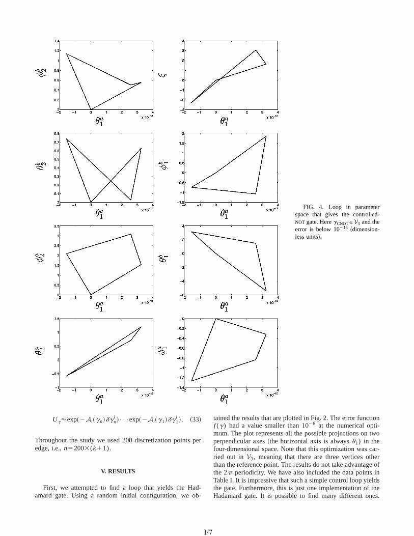
-
REALIZATION OF ARBITRARY GATES IN HOLONOMIC . . . PHYSICAL REVIEW A67, 012319 ~2003!
FIG. 4. Loop in parameterspace that gives the controlledNOT gate. HeregCNOTPV3 and theerror is below 10213 ~dimension-less units!.
p
db
ion
two
ar-ere ofin
ldsthees.
Ug'exp~2Ai~gn!dgni !•••exp~2Ai~g1!dg1
i !. ~33!
Throughout the study we used 200 discretization pointsedge, i.e.,n52003(k11).
V. RESULTS
First, we attempted to find a loop that yields the Haamard gate. Using a random initial configuration, we o
01231
I/7
er
--
tained the results that are plotted in Fig. 2. The error functf (g) had a value smaller than 1028 at the numerical opti-mum. The plot represents all the possible projections onperpendicular axes~the horizontal axis is alwaysu1) in thefour-dimensional space. Note that this optimization was cried out in V3, meaning that there are three vertices oththan the reference point. The results do not take advantagthe 2p periodicity. We have also included the data pointsTable I. It is impressive that such a simple control loop yiethe gate. Furthermore, this is just one implementation ofHadamard gate. It is possible to find many different on
9-7
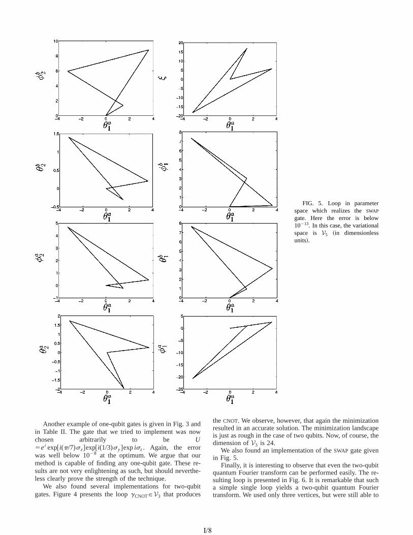
l
NISKANEN, NAKAHARA, AND SALOMAA PHYSICAL REVIEW A 67, 012319 ~2003!
FIG. 5. Loop in parameterspace which realizes theSWAP
gate. Here the error is below10213. In this case, the variationaspace is V5 ~in dimensionlessunits!.
nw
rr
th
bi
onapethe
bitre-ch
ierto
Another example of one-qubit gates is given in Fig. 3 ain Table II. The gate that we tried to implement was nochosen arbitrarily to be U5ei exp@i(p/7)sz#exp@i(1/3)sy#expisz. Again, the errorwas well below 1028 at the optimum. We argue that oumethod is capable of finding any one-qubit gate. Thesesults are not very enlightening as such, but should neverless clearly prove the strength of the technique.
We also found several implementations for two-qugates. Figure 4 presents the loopgCNOTPV3 that produces
01231
I/8
d
e-e-
t
the CNOT. We observe, however, that again the minimizatiresulted in an accurate solution. The minimization landscis just as rough in the case of two qubits. Now, of course,dimension ofV3 is 24.
We also found an implementation of theSWAP gate givenin Fig. 5.
Finally, it is interesting to observe that even the two-ququantum Fourier transform can be performed easily. Thesulting loop is presented in Fig. 6. It is remarkable that sua simple single loop yields a two-qubit quantum Fourtransform. We used only three vertices, but were still able
9-8

REALIZATION OF ARBITRARY GATES IN HOLONOMIC . . . PHYSICAL REVIEW A67, 012319 ~2003!
FIG. 6. LoopgFourier. The er-ror is below 10213 ~dimensionlessunits!.
ineenoiafu
bete.altyrolss
ofol
find an acceptable solution. We argue that the error canmade arbitrarily small for any two-qubit gate.
VI. DISCUSSION
The realization of arbitrary one- and two-qubit gatesthe context of holonomic quantum computation has bdemonstrated. By restricting the loops in the control mafold within a polygon withk vertices, it becomes possible tcast the realization problem to a finite-dimensional vartional problem. We have shown explicitly that some use
01231
I/9
be
ni-
-l
two-qubit gates are realized by a single loop.A possible improvement of the present scenario would
to minimize the length of the path realizing a given gaThis can be carried out by introducing an appropriate penor barrier function and the Fubini-Study metric in the contmanifold CP2. This optimization program is under progreand will be reported elsewhere.
ACKNOWLEDGMENTS
A.O.N. would like to thank the Research FoundationHelsinki University of Technology and the Graduate Scho
9-9

ksln,
df
als
NISKANEN, NAKAHARA, AND SALOMAA PHYSICAL REVIEW A 67, 012319 ~2003!
in Technical Physics for financial support; M.N. thanthe Helsinki University of Technology for financiasupport, and he is also grateful for partial support of a Grain-Aid from the Ministry of Education, Culture, Sports
-
01231
I/1
t-
Science, and Technology, Japan~Project Nos. 14540346 an13135215!; M.M.S. acknowledges the Academy oFinland for a Research Grant in Theoretical MateriPhysics.
ht,
@1# J. Gruska,Quantum Computing~McGraw-Hill, New York,1999!.
@2# M.A. Nielsen and I.L. Chuang,Quantum Computation andQuantum Information~Cambridge University Press, Cambridge, 2000!.
@3# A. Galindo and M.A. Martin-Delgado, Rev. Mod. Phys.74,347 ~2002!.
@4# P. Zanardi and M. Rasetti, Phys. Lett. A264, 94 ~1999!.@5# K. Fujii, Rep. Math. Phys.48, 75 ~2001!.@6# D. Ellinas and J. Pachos, Phys. Rev. A64, 022310~2001!.@7# J. Pachos, P. Zanardi, and M. Rasetti, Phys. Rev. A61,
010305~R! ~1999!.@8# J. Pachos and P. Zanardi, Int. J. Mod. Phys. B15, 1257~2001!.@9# J. Pachos and S. Chountasis, Phys. Rev. A62, 052318~2000!.
@10# M. Berry, Proc. R. Soc. London, Ser. A392, 45 ~1984!.@11# A. Zee, Phys. Rev. A38, 1 ~1988!.@12# F. Wilczek and A. Zee, Phys. Rev. Lett.52, 2111~1984!.@13# M. Nakahara,Geometry, Topology and Physics~IOP, Bristol,
1990!.@14# J.C. Lagarias, J.A. Reeds, M.H. Wright, and P.E. Wrig
SIAM J. Optim.9, 112 ~1998!.
9-10
0

����������� �������������� ����������������������������! �"#��$&%(') (*��,+.-.� ��$0/1'32�2�'�465�7�2�8�5�9�9-:<;=��������?>@�+.AA
BDCFEHG�IKJMLONPBQLRBQSPBQIOG�TVUQWXJYSZE[W\I ]\J�EH^H_
`ba�cdcd�def%�ab�g*)hi`ba�j0akFl�monqpsrol�t u�v#w�x�ur1yqu{z|l�}�~�p�l�m1~3psx�����n.t ur����3r�����r���nspqurom�x?~�R�(n�yqw��!~�t ~���x��v=���b���b~������)�����.��nsysw���r1y�l�t(v�w�x�uroy.uo�3�@�@�g�{�������)�����?�d�����@r��,t l��!�
� ��hi��ePab`�hi`��b`�;=`�� fn�¡�l�p.m�¢£nq�,m�~��v#w�x�uroy.u���¤{r¥���¦rf����r���nqpqugrom�x
��r§��l�uw�r¥�q��uql���l£��¨�¨3��©��������0ª�lq¡�l��� `�;�cdc=� � %(*)`�«�e � `�`
kFl�monspsr1l�t u�v#w�x�ur1yqu{z|l�}�~�p�l�m1~3psx�����n.t ur����3rf�|��r¥��nqpqur&m�x?~�£��nsysw��!~�t ~s��x��v=���b���b~������)�����.��nsysw���r1y�l�t(v�w�x�uroy.uo�3�@�@�g�{�������)�����?�d�����@r��,t l��!�
;=+.-.+.� ¬�+.��*)+q���+.f,+q�b®�2� ('�2�2)'
¯ +�A������°��±�+²-.����Ag�g���-q�� ���H���0±���$�������f°�$ �)����A��)���+q�� -.��$ $ °H� �[���+q��$ ��³.���������´o������+q�,+.����+q�����)��+.$@���#±���$ ������R� -�µ����������¶-.������)����� ���!%�cd±�+���� ¶��A{�1·6���§��$ �!%�¸�� �A��. �·6+����+.A+.���i������+.-�±���� µ���+[����¹������ ��ºD�±�+�A��� ����$ +�$��)���\� �Y�±�+�-.�����g���$=R����� ����$ �Y����������°Y����+q´oµ����� �?������1·6��´oµ����� �f����� ����g°[º����+.Aq%£*)+.-.�����! |·6+���+q¬�+q$����F�±�+������R��$�� A»�����g�±�+s�������F�����[�?�,+.����$ �1°�+q�¼�������±�+f$�+q��º��±������±�+²$ �)���| (�±�+q�+q�°����������ºR��£�� ������ ³.+i�±�+²+s½�+.-q�������������+������b�±�+µ����������¾-q������������ ���,%#e����6�+q�±��)�R����3¬)� ��+.A6�²º�+q��+q���$(�+.����A#)°�·=±�� -s±£±���$�������f°�$ �)����A-.���Y,+¿�+q��$ ��³.+q�Y���Y���M+q½)�,+q�� �+.�����$bAg+q����|%P*)� ��-.+�±���$����������-¿µ����������K-.����������������M��A������������� -� ������� R� ³.� ��º²·=� �±��+.Ag�,+.-q�6��²�±�+i$�+q��º��±?���|�±�+i$��)���¿R�¦°R����¦¬�+i-q���-.����$&%¤fnqx�À6~�p���u�Á µ)��������� º�+.���+q�g�� -{����������,��$���º�� -.��$!-.������������ ����Aq ������+q�� -.��$!��������� ³.���� ��� ~�¢�¢�Ã���r1y�l�mons�£}sx,Á ;P��$�+q¬�+
Ä0Å G)Æ#Ç)È�ÉdÊ�ËbÌ(Ç�Í1É�ÆÎÐÏ�Ñ.Ò3Ó�Ô�Õ�Ò3Ö@ϲ×&ØQÙ@Ú&Ï)ØQÏ�Û|Ò�Ü�Ò3×oÝ(ÛHÝ,Þ@Ü?ß|Ó@Ü(Û!Ò3Ó�ØOà�Ý,ØQÙ@Ó�Ò3Ï�á{Û|Ó�ØâÏ�á3×&à�Ü(Ú&Ú¥Õ�Ó�Ѧ×oÛ�ã�ѦÝ(äà)Ü(Ú&ÚoÏ�ÔFÛ�Ý,Û�äå�æ�Ï)Ú&×oÜ(ÛÖ�Ý,Ú&Ý,Û�Ý,ØQ×&Ï)Ñ�çiè?Ý(ÚoÝ(Û@Ý(Øâ×&à¿ß|Ó@Ü(Û!Ò3Ó�Øéà)Ý,ØDÙ@Ó�Ò�Ü�Ò3×&Ý,ÛëêgèHì�íRîiï�Ü(ÑRѦÓ�ã,ã,Ï�Ñ.Ò3Ï)ÔYæ|ÕZð#Ü(Û@Ü�á3Ô�×=Ü(Û�Ôòñ?Ü�ѦÏ�Ò¦Ò3××&ÛZñ£Ï)Þ�çió�ô�õ{Ü�Û@ÔZÞ�Ó�á¦Ò3Ö�Ï�á�Ô@Ï�ö!Ï�Ú&Ý(Ù�Ï)Ô6÷0Ï,ç ã�ç&÷#×oÛZñ£Ï�Þ�Ñ�çió ø�÷6ù|÷#ú�÷6û�÷�ü�÷dý|÷6þ�õgçRÿqÛZÝ(á3Ô�Ï�á�Ò3Ýâæ@Ó�×&ÚoÔ ÜDï�Ý(á � ä×&Û�ãPß|Ó@Ü(Û!Ò3Ó�Ø à�Ý,ØDÙ@Ó�Ò3Ï�áFÝ,Þ�� ß|Ó�æ@×¥Ò3Ñ�÷{Ý,Û�ÏMÖ@Ü(Ñ[Ò3ÝXæ6ÏMÜ�æ@Ú&ÏâÒ3ÝZÙ�á3Ý�Ô�Ó�à�ÏòÜ�Û|Õ Ó�Û@×¥Ò�Ü�á¦ÕëÝ(Ù�Ï�á�Ü�Ò3×&Ý,Û�Ñ×&Û��Dê�ø���î�÷²×ç Ï,ç¾Ò3×&ØâÏ�äÏ�ö!Ý,Ú&Ó�Ò3×oÝ(Û@Ñ�÷fÝ,Û¾Ò3Ö�ÏZß!Ó�æ@×¥Ò3Ñ�ç¾ÿqÛ Ö�Ý,Ú&Ý,Û�Ý,ØQ×oà\ß|Ó@Ü(Û!Ò3Ó�Ø à�Ý,ØDÙ@Ó�Ò�Ü�Ò3×oÝ(Ûd÷�Ò3Ö@Ï�ѦÏÝ(Ù�Ï�á�Ü�Ò3×&Ý,Û�ÑRÜ�á3ÏHÜ�à�Ö�×&Ï�ö,Ï)ÔYæ|ÕòѦÏ�Ú&Ï)à�Ò3×&Û@ã Ü Ô�Ï)ã,Ï�Û�Ï�á�Ü�Ò3ÏHß!Ó�æ@×¥ÒRÑ.Õ�Ñ.Ò3Ï�Ø Ü(Û�ÔXÜ(Ú&ÚoÝ)ï£×oÛ�ã Þ1Ý(á£Ü(Û\Ü(Ô�×1Ü�æ#Ü�Ò3×oàÒ3×&ØQÏ�äÔ�Ï�ö!Ï)Ú&Ý(Ù@ØQÏ)Û!Ò¿Ò3Ö@Ü�ÒHÔ@Ý|Ï)ÑHÛ�Ý(Ò[à�Ö@Ü(Û�ã,ÏQÒ3Ö�ÏQÔ�Ï)ã,Ï�Û�Ï�á�Ü�à�ÕPÑ.Ò¦á3Ó�à�Ò3Ó�á3Ï(ç��ö!Ï�ÛëÒ3Ö�Ý,Ó�ã,ÖëÒ3Ö@ÏQè¿Ü(ØQ×&Ú&äÒ3Ý,Û�×oÜ(ÛX×&Û\Ò3Ö�×oѣѦÓ�æ@Ñ.Ù0Ü(à)Ï[×&Ñ£à)Ý(ØQÙ@Ú&Ï�Ò3Ï�Ú¥ÕMÒ¦á3×&ö�×1Ü�Ú÷�×¥ÒRÒ3Ó�á3Û�Ñ�Ý(Ó�Ò£Ò3Ö@Ü�Ò�ÜQÛ@Ý(Û�äå�æ�Ï�Ú&×1Ü�ÛZÜ(Û�ÔZ×¥á¦á3Ï)Ô�Ó�à)×¥æ@Ú&Ïã!Ü�Ó@ã(Ï[Ù�Ý(Ò3Ï�Û!Ò3×oÜ(Ú=Ü�Ù�Ù�Ï)Ü�á3Ñ�÷#Ó�Ѧ×&Û�ãQï£Ö�×oà�ÖZÜ(Û!ÕXÓ�Û�×&Ò�Ü�á¦ÕòÏ�ö,Ý,Ú&Ó�Ò3×&Ý,Û\à�Ü(Û\æ�ÏHà�Ü�á¦á3×oÏ�ÔXÝ,Ó�Ò)ç�å?ÑRÒ3Ö�ÏHï�Ý(á3ÔÖ�Ý,Ú&Ý,Û�Ý,Ø[ÕD×¥Ò3ѦÏ�Ú&Þ#ѦÓ�ã,ã,Ï�Ñ.Ò3Ñ�÷!ï�Ï£Ô�á3×¥ö!Ï�Ò3Ö�ÏRÑ.Õ�Ñ.Ò3Ï�Ø Ü�á3Ý,Ó�Û�ÔâÚ&Ý�Ý(Ù@Ñ�×&ÛDÒ3Ö�ÏRà)Ý(Û|Ò¦á3Ý(Ú&ägÙ0Ü�á�Ü�ØâÏ�Ò3Ï�á�Ñ.Ù0Ü(à�Ï[êgÝ�á
�.`�$ A� ���R�±�+ � ���+s�����$�AR>0±�°)A� -.A£«���,���������g°� d��+.$ A� ��)� ����� ¬�+q�Ag� �1°Y����c�+.-s±�����$ ��º�°� d>�%def%����3½Y'�'32�2Y/&c�+.-�±���� -.��$>0±�°)A� -.As4� �¸���a=´o2)'�2��35�� ��c{ �¸�� ��$������!%
5�7�2
II/1
Reprinted with permission from the publisher. APPENDIX IIIn: Quantum Information and Computation 2002.Vol. 2, Special, pp. 560–577.
� �1�=����r¥u��l3�!nq�(��k ���il���l3w�l�p�l�l3�!��k � k ���,l�t ~�¢£l�l 5�7��
ØâÜ(Û�×&Þ�Ý,Ú&Ô#î�Ü�Û@ÔXÜ(Þ1Ò3Ï�á£Ï�Ü�à�ÖXÚ&Ý�Ý(Ù\Ò3Ö�Ï�á3Ï�×&Ñ�ÜDÛ@Ý(Û|Ò¦á3×¥ö�×oÜ(Ú6à�Ö@Ü(Û�ã,ÏH×&Û\Ò3Ö�ÏHÑ.Ò�Ü�Ò3ÏHÝ,ÞbÒ3Ö�ÏHÑ.Õ�Ñ.Ò3Ï�ØXç���Ö�×oÑR×&ÑÜDã,Ï�Û@Ï�á�Ü(Ú&×���Ü�Ò3×oÝ(ÛòÝ,Þ=Ò3Ö�ÏHÞ�Ü(ØâÝ(Ó@Ñ���Ï�á¦á¦ÕYÙ@Ö@Ü(ѦÏYó �õdÒ3ÝâÜDÔ�Ï)ã(Ï)Û�Ï�á�Ü�Ò3ÏHÑ.Õ�Ñ.Ò3Ï)Ø\ç
��Ö�×oÑiÙ#Ü�Ù6Ï�á²×&Ñ�Ý(á3ã!Ü(Û�×���Ï)ÔâÜ(ÑfÞ�Ý,Ú&Ú&Ý�ï£Ñ�ç�ÿqÛ�|Ï�à�Ò3×&Ý,ÛMø?ï�Ï���á3Ñ.Òfá3Ï�ö�×oÏ�ï Ò3Ö�Ï£à�Ý,Û�à)Ï�Ù�Ò²Ý(Þ6Û�Ý,Û�äå�æ�Ï)Ú&×oÜ(ÛÖ�Ý,Ú&Ý,Û�Ý,Ø[Õ!ç ��Ö@Ï�Û ×&Û�|Ï�à�Ò3×&Ý,ÛÐùMï�Ïâ×&Û!Ò¦á3Ý�Ô�Ó�à)ÏQÝ(Ó�áHá3Ï�Ü�Úo×��)Ü�Ò3×&Ý,Û�ä×&Û@Ô�Ï�Ù�Ï)Û�Ô�Ï)Û!Ò¿ØâÝ�Ô�Ï�Úgç �¿Ü�ØâÏ�Ú¥Õ!÷6ï�Ïà�Ý,Û�Ѧ×&Ô@Ï�áQÒ3Ö@Ï\ã,Ï�Û�Ï�á�Ü�ÚRѦÏ�Ò¦Ò3×&Û�ã Þ1Ý(áâÛ�Ý,Û�äå�æ�Ï)Ú&×oÜ(Û Ö�Ý,Ú&Ý,Û�Ý,Ø[Õ¾Ü(Û�Ô¼Ó�Û�×¥Ò�Ü�á¦Õ ã!Ü�Ò3Ï\à�Ý,Û�Ñ.Ò¦á3Ó�à�Ò3×&Ý,Û ×&Û ÜÒ3Ö�á3Ï�Ï�äÑ.Ò�Ü�Ò3Ï\Ñ.Õ�Ñ.Ò3Ï)Ø\ç���Ö�×&ÑQÙ0Ü�á¦ÒMÜ�Ù@Ù@Ú&×&Ï)Ñ Ò3Ý ÜëØFÓ�à�Ö¾ï£×oÔ�Ï�áâà�Ú1Ü�ѦÑâÝ,Þ�á3Ï�ѦÏ)Ü�á3à�Ö Ò3Ý(Ù@×&à�ÑQ×&Û ØâÝ�Ô�Ï�á3ÛÙ@Ö!Õ�Ѧ×&à)ÑdÒ3Ö@Ü(Û��¦Ó�Ñ.Ò�ß|Ó@Ü(Û!Ò3Ó�Ø à�Ý,ØDÙ@Ó�Ò�Ü�Ò3×oÝ(Ûdç��PÜ(Û!Õ¿Ù@Ö|Õ�Ѧ×oà)Ü(Ú,Ñ.Õ�Ñ.Ò3Ï�ØâÑ=ØâÜ)Õ?æ6Ï�ѦÓ�×¥Ò�Ü�æ@Ú&Ï�Þ�Ý�á=Ò3Ö�ϲÜ�à�Ò3Ó@Ü(Ú×&ØDÙ0Ú&Ï�ØâÏ�Û!Ò�Ü�Ò3×&Ý,ÛQÝ,Þ�Ò3Ö�×&ÑfØQÝ�Ô�Ï)Úgç�|Ï)à�Ò3×&Ý,Ûâú[×&ÑfÒ3Ö�Ï�ØâÜ(×&ÛQÙ0Ü�á¦Ò�Ý(Þ�Ò3Ö@ÏRï�Ý(á � ç���Ö�Ï�á3Ï£ï�Ï���á3Ñ.Ò�à)Ý(Û@Ѧ×&Ô�Ï�áÒ3Ö�Ï ã,Ï�Û�Ï�á3×&àDÜ(Ú&ã,Ý(á3×¥Ò3Ö�Ø Þ1Ý(á�Û|Ó�ØâÏ�á3×&à�Ü�ÚoÚ¥Õ��0Û�Ô�×&Û�ãò×oØDÙ@Ú&Ï)ØQÏ)Û!Ò�Ü�Ò3×&Ý,Û�Ñ�Ý(ÞfÖ�Ý,Ú&Ý,Û�Ý,ØQ×&à ß|Ó@Ü(Û!Ò3Ó�Ø ã!Ü�Ò3Ï�Ñ�çÎÐÏQÖ@Ü)ö!Ï Ù@á3Ï�ö�×&Ý,Ó�Ñ¦Ú¥Õ Ñ.Ò3Ó�Ô@×&Ï�ÔPÒ3Ö�ÏQà)Ý(ØQÙ@Ó�Ò�Ü�Ò3×&Ý,Û@Ü(Ú{à�Ý,Û�Ñ.Ò¦á3Ó�à�Ò3×&Ý,ÛëÝ,ÞfÖ�Ý,Ú&Ý,Û�Ý,ØQ×oàDß|Ó@Ü(Û!Ò3Ó�ØVã,Ü�Ò3Ï)Ñ�×&Ûñ£Ï�Þsç�ó�ô���õç���Ö�Ï�á3ÏFï�Ï Ú&×&ØQ×&Ò3Ï�ÔXÝ,Ó�á�Ü�Ò¦Ò3Ï)Û!Ò3×&Ý,Û6÷�Ö�Ý�ï�Ï�ö,Ï�á)÷�Ò3ÝMÒ3Ö�Ï Ñ¦Ý(ÚoÓ�Ò3×&Ý,ÛZÝ,ÞiÒ3Ö�Ï ×&Û!ö!Ï�á3Ѧ×&Ý,ÛZÙ�á3Ý(æ@Ú&Ï)Ø×¥Ò3ѦÏ�ÚoÞ���ï�Ï Ñ¦Ö�Ý�ï�Ï�ÔPÒ3Ö0Ü�Ò¿Ý,Û�Ï à�Ü(Û Û�Ó�ØQÏ�á3×&à)Ü(Ú&Ú¥Õ��@Û�Ô ÜMÖ�Ý,Ú&Ý,Û�Ý,ØFÕXÚoÝ|Ý(ÙPà)Ý(á¦á3Ï�Ñ.Ù�Ý,Û�Ô�×oÛ�ãMÒ3Ý\ÜMÔ�Ï)Ѧץá3Ï�Ôã!Ü�Ò3Ï,ç è?Ï�á3Ï ï�ÏDÞ1Ó�á¦Ò3Ö�Ï�á�Ï���Ò3Ï�Û�ÔPÒ3Ö�ÏDà�Ý,Û�à)Ï�Ù�Ò�Ò3Ý\Ü(à�Ò3Ó0Ü�ÚoÚ¥ÕZÝ(Ù�Ò3×&Øâ×���×oÛ�ãâï£×¥Ò3ÖPá3Ï�Ñ.Ù�Ï)à�Ò¿Ò3ÝòÒ3Ö�ÏDÚ&Ï�Û�ã(Ò3ÖÝ,Þ�Ò3Ö�ÏâÙ0Ü�Ò3Ö6çXÎÐÏ �@Û�Ô Ñ¦Ý(ØâÏâÛ@Ï�ïéÜ(Û�Ô ØQÝ(á3ÏMÏ �âà�×&Ï)Û!ÒF×&ØQÙ@Ú&Ï)ØQÏ�Û|Ò�Ü�Ò3×oÝ(Û@Ñ�Ý,Þ�Ö�Ý,Ú&Ý,Û�Ý,Øâ×&àMß|Ó@Ü(Û!Ò3Ó�Øã!Ü�Ò3Ï)Ñ�ç!��Ï)à)Ü(Ó�ѦÏQÖ�Ý,Ú&Ý,Û�Ý,ØQ×&àDß|Ó@Ü(Û!Ò3Ó@Ø à)Ý,ØDÙ@Ó�Ò�Ü�Ò3×&Ý,Ûë×&ÑHÜ(Ô�×oÜ�æ0Ü�Ò3×&àQÜ(Û�Ô Ö�Ï�Û�à)ÏDÒ3×&ØQÏ�äà�Ý,Û�ѦÓ�Øâ×&Û�ã�÷d×¥Ò×&Ñ�×&ØDÙ6Ý�á¦Ò�Ü(Û!Ò�Ò3Ý Ý(Ù�Ò3×&Øâ×���Ï�Ò3Ö�Ï?à)Ý,Û�Ñ.Ò¦á3Ó�à�Ò3×oÝ(ÛòÝ,Þ=ß|Ó@Ü(Û!Ò3Ó@Øéã!Ü�Ò3Ï)Ñ�ç{ÎÐÏ�Ü�á3ã,Ó�Ï?Ò3Ö@Ü�Ò�Ý,Ó�áRÝ(Ù�Ò3×&Øâ×��)Ü�Ò3×&Ý,ÛØQÏ�Ò3Ö�Ý�Ô\à)Ý,Ó�Ú&ÔZÜ(Ú&ѦÝQæ�ÏHÏ ��Ò3Ï)Û�Ô�Ï�Ô\Ò3ÝâÔ�Õ�Û@Ü(ØQ×&à�Ü�Úbß!Ó0Ü�Û|Ò3Ó�Ø à�Ý,ØDÙ0Ó�Ò�Ü�Ò3×&Ý,Û6ç�|Ï�à�Ò3×&Ý,ÛZûD×&Ñ£Ô�Ï�ö!Ý(Ò3Ï�ÔXÒ3ÝÔ�×&Ѧà)Ó�ѦѦ×&Ý,Û6ç
"�Å SXÉ�Æ$#�J %�&�'�Í)(#ƼN\É*'1É�Æ=É*+-,
ÎÐÏ\æ�á3×&Ï�.�Õ Ý,Ó�Ò3Úo×&Û�ÏòÒ3Ö�ÏXà�Ý,Û�à�Ï�Ù�ÒâÝ,Þ?Û�Ý,Û�äå�æ�Ï�Úo×oÜ(Û Ö�Ý,Ú&Ý,Û�Ý,Ø[Õ Ü�ѦѦÝ�à)×oÜ�Ò3Ï�Ô¾ï£×¥Ò3Ö Ü(Ô�×oÜ�æ0Ü�Ò3×&à\à�Ö0Ü�Û@ã(ÏÝ,Þ�à�Ý,Û!Ò¦á3Ý,ÚbÙ0Ü�á�Ü�ØâÏ�Ò3Ï�á3Ñ�ç/��Ö�×&Ñ?×&Ñ¿Û�Ï�à)Ï�ѦÑ3Ü�á¦ÕZÛ�Ý(Ò¿Ý,Û�Ú&Õ\Ò3ÝYÏ�Ñ.Ò�Ü�æ@Ú&×&ѦÖPÛ�Ý(Ò�Ü�Ò3×oÝ(Û à�Ý,Û!ö!Ï)Û!Ò3×&Ý,Û�Ñ?æ@Ó�ÒHÜ�ÚoѦÝÒ3Ý á3Ï�à�Ò3×&Þ1Õ à�Ï�á¦Ò�Ü(×&Û¼à)Ý(Û@Þ1Ó�Ѧ×oÝ(Û<Ü�Ù�Ù6Ï)Ü�á3×&Û�ã ×&Û¼Ò3Ö�Ï Úo×¥Ò3Ï�á�Ü�Ò3Ó�á3ÏZÝ,Û»Ò3Ö�Ï Ô�Ï��@Û�×¥Ò3×&Ý,Û»Ý(Þ�Ò3Ö�Ï Ö�Ý,Ú&Ý,Û�Ý,ØFÕÝ(Ù�Ï�á�Ü�Ò3Ý(á)ç0��Ö�Ï[à�Ý,Û�à�Ï�Ù�Ò£ï�Ü�Ñ���á3Ñ.Ò?×&Û!Ò¦á3Ý�Ô�Ó�à)Ï�Ô\æ�ÕòÎ<×&Úoà���Ï � Ü(Û�Ôëð#Ï�Ï[×&ÛXñ£Ï�Þsç{ó§ô,ô�õgç�1�Ò3Ö�Ï�á?Ï ��à�Ï)Ú&Ú&Ï�Û|Òá3Ï�Þ�Ï�á3Ï)Û�à�Ï)Ñ£Ü�á3Ï ð#Ï�ÏYó§ô�ø�õbÜ(Û�Ô��PÝ(Ñ.Ò�Ü(Þ�Ü2�)Ü(Ô�Ï�Ö ó�ô�ù�õç
3bÏ�ÒHÓ@ÑHà�Ý,Û�Ѧ×&Ô�Ï�á[ÜòÞ�Ü(ØQ×&Ú&ÕZÝ,Þ²è¿Ü(ØQ×&Ú¥Ò3Ý,Û�×1Ü�Û@Ñ547698�:âÙ0Ü�á�Ü(ØQÏ�Ò3Ï�á3×���Ï)Ô æ|Õ<;�=�> ÷=ï£Ö�Ï�á3Ï > ×&ÑHÜØâÜ(Û�×&Þ�Ý,Ú&ÔDà)Ü(Ú&Ú&Ï)ÔFÒ3Ö�ÏRà)Ý,Û!Ò¦á3Ý,Ú�ØâÜ(Û�×&Þ�Ý,Ú&Ô6ç?��Ö�ÏRÚ&Ý�à)Ü(Ú�à�Ý�Ý(á3Ô�×&Û@Ü�Ò3Ï�Ý,Þ$;Q×&Ñ�Ô�Ï�Û@Ý�Ò3Ï)ÔDæ|Õ@;BA�ê¦ô/CED�CEFHGÔ�×&Ø�> î�çbÎÐÏ�Ü(ѦѦÓ�ØâÏ�Ò3Ö@Ü�ÒdÒ3Ö�Ï�á3ϲÜ�á3ÏfÝ(Û@Ú¥Õ�Ü��0Û�×¥Ò3Ï�Û|Ó�Ø[æ6Ï�ábÝ,Þ�Ï�×oã(Ï)Û!ö(Ü(Ú&Ó@Ï�ÑJILK�ê�;�î�ê¦ô�C�M�CEN[î�Þ1Ý(á�Ü(ÛÜ�á¦æ@×¥Ò¦á�Ü�á¦ÕHÙ6Ý(×oÛ!Ò�;QÝ(ÞO> Ü�Û@ÔFÒ3Ö@Ü�ÒiÛ�Ý¿ÚoÏ�ö!Ï�Ú�à�á3Ý,ѦѦ×&Û@ã(Ñ{Ò�Ü � Ï�Ù@ÚoÜ(à�ϲÒ3Ö�á3Ý(Ó@ã(ÖQÜ(Ú&Ú�Ý,ÞO> çP��Ö�Ï�Ï�×oã(Ï)Û!ö(Ü(Ú&Ó@ÏILK�ê�;�îf×oÑ£Ü�ѦѦÓ@ØQÏ�Ô\Ò3ÝDæ�Ï/QRK�äÞ�Ý,Ú&Ô\Ô�Ï)ã(Ï)Û�Ï�á�Ü�Ò3ÏH×&Û�Ô�Ï�Ù�Ï�Û�Ô@Ï�Û!Ò3Ú¥ÕYÝ,ÞP;dç���Ö�×&Ñ£Ô�Ï�ã,Ï�Û@Ï�á�Ü�Ò3Ï�ѦÓ�æ@Ñ.Ù0Ü(à�ÏHï£×&Ú&Úæ�ÏMÔ�Ï)Û�Ý(Ò3Ï�ÔÐæ|ÕTS�K�ê�;�î�çU��Ö�Ï�ÛÐÒ3Ö@Ïâè¿Ü(ØQ×oÚ¥Ò3Ý,Û�×oÜ(Ûë×oÑ[Ï ��Ù�á3Ï)ѦѦÏ�Ô Ü(Ñ Ü�Û �WV � Ö@Ï�á3ØQ×&Ò3×oÜ(Û ØâÜ�Ò¦á3×X��÷ï£Ö�Ï�á3Ï �YG[Z]\K�^`_ QaK|ç
3bÏ�Ò£Ó�Ñ£Ô�Ï�Û@Ý�Ò3Ï�Ò3Ö�Ï�Ý(á¦Ò3Ö�Ý,Û�Ý(á3ØMÜ�Ú6æ0Ü(Ѧ×&ÑRö!Ï�à�Ò3Ý(á3ÑRÝ,ÞbS�K�ê�;�î²Ü(Ñ/4dc M�e��f;$gh:R�
698*c Mie��j;*g�GkILK�ê�;�î�c Miel�f;*gfm n�oae��j;?c Mapl�f;*gPGkq rfKsq�tRu$v ê¦ô�î
�?Ý(Ò3Ï¿Ò3Ö@Ü�Ò�Ò3Ö@Ï�á3ÏHÜ�á3Ï � êwQaK,î²Ô�Ï�ã(á3Ï)Ï�Ñ£Ý(Þ�Þ1á3Ï�Ï�Ô@Ý(Ø ×&ÛXà�Ö�Ý�Ý,Ѧ×&Û�ãDÒ3Ö�ÏHѦÏ�Ò�Ý(Þbæ0Ü(Ѧ×&Ñ�ö!Ï�à�Ò3Ý(á3Ñx4�c M�e��f;*gh:!ç|Ó�Ù�Ù�Ý,ѦÏQÒ3Ö�ÏQà�Ý,Û!Ò¦á3Ý,Ú{Ù0Ü�á�Ü(ØQÏ�Ò3Ï�áy;Ð×&Ñ�ö(Ü�á3×&Ï�Ôëà)Ý,Û!Ò3×&Û|Ó�Ý,Ó�ѦÚ&ÕPÝ�ö,Ï�áy> çDÿsÒ[×&ÑHÜ(ѦѦÓ�ØâÏ�ÔëÒ3Ö0Ü�ÒHÒ3Ö�Ï
ö(Ü�á3×oÜ�Ò3×&Ý,ÛÐ×oÑ[ѦÝPѦÚ&Ý�ï Ò3Ö@Ü�Ò[Ò3Ö@ÏYÜ(Ô�×oÜ�æ0Ü�Ò3×&à�×&ÒsÕëà�Ý,Û�Ô@×¥Ò3×&Ý,ÛÐ×&Ñ Þ1Ó@ÚX�@Ú&Ú&Ï)Ô6÷{×gç Ï,ç¥÷{Ò¦á�Ü�Û@ѦץÒ3×&Ý,Û�Ñ[æ�Ï�Òsï�Ï)Ï�Û Ò3Ö�ÏÔ�×Xz�Ï�á3Ï�Û!Ò[Ï)Û�Ï�á3ã(ÕëÚ&Ï�ö,Ï)Ú&ÑHÜ�á3ÏâÛ�Ï�ã,Ú&×&ã,×¥æ0Ú&Ï(çQÎÐÏQï£×&Ú&Ú{æ�Ïâà�Ý,Û�à�Ï�á3Û�Ï�Ô ï£×¥Ò3ÖÐÜòÙ0Ü�á¦Ò3×&à�Ó@ÚoÜ�áHѦÓ�æ@Ñ.Ù#Ü�à)Ï(÷�Ò3Ö�Ïã(á3Ý(Ó@Û�Ô Ñ.Ò�Ü�Ò3ÏlS{_)÷,Þ�Ý�áiÏ ��Ü(ØDÙ@Ú&Ï,ç=ÎÐϲï£×&Ú&Ú�Ô�á3Ý(Ù Ò3Ö�Ï�×&Û�Ô@Ï �|M GOô²Ö@Ï�á3Ï)Ü(Þ1Ò3Ï�á�Ò3Ý?Ѧ×oØDÙ@Ú&×oÞoÕ�Ò3Ö�Ï�Û�Ý(Ò�Ü�Ò3×&Ý,Û6ç3=Ï�Ò¿Ó�Ñ�Ò�Ü � Ï ÜMæ0Ü(Ѧ×&Ñ?ö,Ï)à�Ò3Ý(á9c e��f;=ê}�|î~gRÜ�Ò���G��òÜ�Û@Ô Ñ.Ò3Ó@Ô�ÕZÖ�Ý�ïOÒ3Ö�Ï Ñ.Ò�Ü�Ò3Ï Ô�Ï�ö!Ï�ÚoÝ�Ù0Ñ¿Ü�Ñ�ÜMÞ1Ó@Û�à�Ò3×&Ý,ÛÝ,Þ²Ò3×&ØQÏ,çDÎÐÏâØâÜ)Õ Ü�ѦѦÓ@ØQÏQÒ3Ö@Ü�Ò5I|ê�;�î/G��\Þ1Ý(áFÜ(Û!Õ<;�=E> ÷=Ù�Ý,ѦѦץæ@Ú&ÕëÜ(Þ1Ò3Ï�á���á3Ñ.ÒHá3Ï�Ü(Ôs�.Ó@Ñ.Ò3×&Û�ã\Ò3Ö�Ï
II/2

5�7�' ��¡,m�r�¢�l�t!w�~�t ~��!~3¢�roy��sÃ(l��,m�Ã�¢ ��l�mon.u
��Ï�á3Ý�ägÙ6Ý(×oÛ!Ò£Ý,Þ=Ò3Ö�ÏHÏ�Û�Ï�á3ã(Õ,ç��?Ý�ï Ý,Ó�áRÒ�Ü(Ñ � ×&Ñ�Ò3ÝQѦÝ,Ú¥ö!Ï¿Ò3Ö�Ïy|à�Ö�á��Ý,Ô�×&Û�ã,Ï�á£Ï�ß!Ó0Ü�Ò3×oÝ(ÛD �� � c �Pt=êw�3î~gPGk6 8���� c �?t=êw�3î~g ê�ø,î
ï£×¥Ò3Ö\Ò3Ö�Ï[×&Û�×¥Ò3×oÜ(Údà�Ý,Û�Ô�×&Ò3×&Ý,Û c �Pt=ê}�|î~g�G�c e��f;bê}�!î~g�çfÿsÒ�Þ�Ý,Ú&Ú&Ý�ï£Ñ£Þoá3Ý,Ø Ò3Ö�Ï[Ü(Ô�×oÜ�æ0Ü�Ò3×&à�×&ÒsÕYà�Ý,Û�Ô�×&Ò3×&Ý,ÛòÒ3Ö0Ü�ÒÒ3Ö�Ï�ѦÝ,Ú&Ó�Ò3×&Ý,Û\Ý,Þ=Ò3Ö�Ï[Ü�æ�Ý�ö,ÏHÏ)ß|Ó@Ü�Ò3×&Ý,Û\ØâÜ)Õ\Ü�Ú&ï�Ü�Õ�Ñ�æ�ÏHÏ ��Ù0Ü(Û�Ô�Ï)ÔX×&ÛòÒ3Ö�ÏHÞ1Ý(á3Ø
c �Pt=êw�3î~gPG � ua^?_
c p��j;=êw�3î~g �`uRt=êw�3îfv ê�ù,î
��Ö�Ï Ó�Û�×&Ò�Ü�á3×&ÒsÕ\Ý,ÞiÒ3Ö�ÏFØMÜ�Ò¦á3×�� �`uatPÞ�Ý,Ú&Ú&Ý�ï£Ñ�Þ1á3Ý,Ø Ò3Ö�Ï à�Ý,Û�Ô�×¥Ò3×oÝ(Û�n��`udêw�3î�c �Ptdêw�3î~g0G q�uRtdçx�²ÕZѦÓ�æ0Ñ.Ò3×¥äÒ3Ó�Ò3×&Û�ã �²ß0çdê�ù!î²×&Û!Ò3Ý �²ß@ç=ê�ø!î�÷�ï�Ï/�@Û�Ô\Ò3Ö@Ü�Ò
��Pt2u G���� � ^?_� pl�j;=êw�3î�����
�� � ������ �j;=êw�3î�� � � tJv êgú|î
��Ö�ÏHÞ�Ý�á3ØMÜ(Ú6ѦÝ(ÚoÓ�Ò3×&Ý,Û\Ý,Þ=Ò3Ö@ÏHÜ�æ�Ý�ö!Ï�Ï)ß|Ó@Ü�Ò3×&Ý,Û\×&Ñ�á3Ï)Ü(Ô�×oÚ¥ÕMÝ(æ�Ò�Ü(×&Û@Ï�ÔXÜ(Ñ
� êw�3î G � Ï ��Ù���� � �!#" ê�$�î � $&%G '(�#� �!#" ê�$�î � $*)+�
�! � $,�.-! � $0/ " ê�$�î " ê�$0/1î1)kv�v�v ê�û,î
ï£Ö�Ï�á3Ï2� ×&Ñ�Ò3Ö@Ï?Ò3×oØQÏ�äÝ(á3Ô�Ï�á3×&Û�ãDÝ(Ù�Ï�á�Ü�Ò3Ý�á�Ü(Û�Ô
" uRt=êw�3îPG � p��j;=êw�3î ������ � ���� e��f;=êw�3î � v ê�ü,î
3=Ï�Ò£Ó�ÑRÔ@Ï �@Û�Ï�Ò3Ö@Ï/3=×oÏ�ä�Ü(Ú&ã,Ï�æ�á�Ü�ägö,Ü�ÚoÓ�Ï�Ôòà)Ý(Û@Û�Ï�à�Ò3×&Ý,ÛòÝ,Û�Ï�äÞ1Ý(á3Ø
3 uat G � pl�f;=êw�3î�����544; A ���� e��f;=êw�3î�� � ; A êsý(î
æ|ÕYï£Ö@×&à�Ö �Dêw�3î²ØâÜ)ÕYæ�ÏHÏ ��Ù�á3Ï�ѦѦÏ)ÔZÜ�Ñ
�Dêw�3î�G76ÐÏ ��Ù98���� 8����8:� ! 3(; m ê�þ,î
ï£Ö�Ï�á3Ï<6 ×&Ñ�Ò3Ö�Ï�Ù0Ü�Ò3Ö�äÝ(á3Ô�Ï�á3×&Û@ãDÝ(Ù�Ï�á�Ü�Ò3Ý�á)ç��?Ý(Ò3Ï¿Ò3Ö@Ü�Ò 3 ×&Ñ£Ü(Û!Ò3×¥äè?Ï�á3ØQ×¥Ò3×oÜ(Û$� 3>= G?� 3 ç|Ó�Ù�Ù�Ý,ѦÏHÒ3Ö@Ü�ÒRÒ3Ö�Ï�Ù0Ü�Ò3Ö ;=êw�3î²×&Ñ�ÜDÚ&Ý�Ý(Ù � êw�3î¿ê}�@CE�0CA@?î�×&Û{> ÷@ѦÓ@à�ÖXÒ3Ö@Ü�Ò � ê}�|î�G � êB@?î�G ; ! ç
��Ö�Ï�ÛX×¥Ò£×&ÑRÞ�Ý(Ó@Û�ÔZÜ�Þ1Ò3Ï�áRÒ¦á�Ü)ö,Ï�á3Ѧ×&Û�ãDÒ3Ö�ÏHÚ&Ý�Ý�Ù � Ò3Ö@Ü�ÒRÒ3Ö�Ï¿á3Ï)ѦÓ�Ú¥Ò3×&Û�ãQÑ.Ò�Ü�Ò3ÏH×&Ñc �Pt=êB@?î~gPG �
u ^`_c pl�f; ! g �buat=êB@?îfv ê�,î
��Ö�ÏHÓ�Û�×&Ò�Ü�á¦ÕòØâÜ�Ò¦á3×X�
� �>C �DêB@?îPG76ÐÏ���ÙD����E � 3 % ê¦ô��!î
II/3
� �1�=����r¥u��l3�!nq�(��k ���il���l3w�l�p�l�l3�!��k � k ���,l�t ~�¢£l�l 5�7�®
×&Ñ¿à�Ü�ÚoÚ&Ï�ÔZÒ3Ö@Ï Ö�Ý,Ú&Ý,Û�Ý,Ø[Õ Ü(ѦѦÝ�à�×1Ü�Ò3Ï)Ô ï£×¥Ò3ÖZÒ3Ö�Ï Ú&Ý�Ý(Ù � ç�ÿsÒ�×oÑ?à)Ú&Ï)Ü�á?Ò3Ö@Ü�Ò � � ×&Ñ¿×&Û�Ô@Ï�Ù�Ï)Û�Ô�Ï�Û|Ò¿Ý,Þ�Ò3Ö�ÏÙ0Ü�á�Ü(ØQÏ�Ò3Ï�á3×��)Ü�Ò3×&Ý,ÛòÞ�Ý(áRÒ3Ö�Ï�Ú&Ý�Ý(Ù\æ@Ó�Ò£Ý,Û�Ú¥ÕòÔ�Ï�Ù�Ï�Û�Ô@ÑRÝ,Û\Ò3Ö�Ï�ã,Ï�Ý,ØQÏ�Ò¦á3×&à¿×&ØMÜ�ã,Ï�Ý,Þ=Ò3Ö@Ï�Ú&Ý�Ý(Ù\×oÛU> ç|Ó�Ù�Ù�Ý,ѦÏ�Ò3Ö@Ï�×&Û�×&Ò3×oÜ(Ú#Ñ.Ò�Ü�Ò3ÏH×&Ñ£ÜDѦÓ�Ù6Ï�á¦Ù�Ý,ѦץÒ3×&Ý,Û
c ��ê}�|î~gPG � ti^`_�� t=êg×oÛ0î�c e��f; ! gfv
��Ö�Ï�Û\Ò3Ö�ÏHÚ&×&Û�Ï�Ü�á3×¥ÒsÕMÝ,Þ=Ò3Ö�Ï||à�Ö�á��Ý(Ô@×&Û�ã,Ï�á�Ï)ß|Ó@Ü�Ò3×&Ý,Û\Ú&Ï)Ü(Ô�Ñ�Ò3ÝDÒ3Ö�Ï/�@Û@Ü(ÚdÑ.Ò�Ü�Ò3Ï
c ��êB@?î~g C � u ^`_ � udêgÝ(Ó�Ò�î�c p��j; ! g
G � u ^`_
c pl�f; ! g �`uRt=êB@?î � t=êg×&Û#î ê¦ô,ô�î
ï£Ö�×&à�Ö ×&ØDÙ@Úo×&Ï�Ñ=Ò3Ö@Ü�Ò � u6êgÝ,Ó�Ò�îPG Z t �`uRt=êB@?î � t=êg×&Û#î�ç?��Ö|Ó�Ñ�÷,ï�Ï�à�Ý,Û��@á3Ø Ò3Ö@Ü�Ò �»×&Ñ�×&Û@Ô�Ï�Ï)Ô[Ò3Ö�Ï�ØMÜ�Ò¦á3×X�á3Ï�Ù�á3Ï)ѦÏ�Û!Ò�Ü�Ò3×&Ý,ÛëÝ,Þ�Ò3Ö�Ï Ò3×&ØQÏ�äÏ�ö!Ý,Ú&Ó�Ò3×&Ý,Û Ý(Ù�Ï�á�Ü�Ò3Ý(á¿ï£×&Ò3ÖZÒ3Ö@ÏDÑ.Ò�Ü(Û�Ô@Ü�á3ÔëÝ(á3Ô�Ï�á3×&Û@ãòÝ,Þf×&Û�Ô�×oà�Ï�Ñ�ç[ÿqÛPÒ3Ö�×&Ñà�Ý,Û!Ò3Ï��|Ò)÷@×¥Ò£×&ÑRà�á3Ó�à)×oÜ(Ú�Ò3Ö@Ü�ÒRÒ3Ö�Ï�ѦÓ@ØQØâÜ�Ò3×&Ý,Û\×&Û �²ß0çdê�ù!î²ã(Ý�Ï)ÑRÝ�ö!Ï�áRÒ3Ö�Ï/��á3Ñ.Ò�×&Û�Ô�Ï�� p²ç
��Ö�ÏHÑ.Ù#Ü�à)ÏHÝ,Þ�Ü(Ú&Ú�Ò3Ö�ÏHÚ&Ý�Ý(Ù@Ñ�æ0Ü(ѦÏ�ÔZÜ�Ò�; ! ×&ÑRÔ�Ï)Û�Ý(Ò3Ï�ÔXÜ(Ñ�l8���ê}>KîPG 4 � � ó �im @�õ�� > c � ê}�|îPG � êB@?îPG]; ! :av ê¦ô�ø,î
��Ö�ÏHѦÏ�Ò£Ý,ÞbÒ3Ö�Ï�Ö@Ý(ÚoÝ(Û@Ý(ØFÕ
è?Ý,Úgê 3 �f; ! îPG 4 � � c � =��l8�(ê}>Kîh: ê¦ô�ù,î
Ö@Ü(ÑbÜ�ã�á3Ý,Ó�Ù[Ñ.Ò¦á3Ó@à�Ò3Ó�á3ÏfÜ(Û�Ô�×&Ñ=à)Ü(Ú&Ú&Ï)Ô?Ò3Ö�Ï�Ö�Ý,Ú&Ý,Û�Ý,Ø[Õ?ã(á3Ý,Ó�Ùdç?��Ö�ÏiÙ�á3Ý�Ô�Ó�à�Òb×&Ñi�¦Ó�Ñ.ÒbÜ(Û�Ý(á3Ô�×&Û0Ü�á¦Õ¿ØMÜ�Ò¦á3×X�Ù�á3Ý�Ô�Ó�à�Ò)ç[ÿsÒH×&Ñ�Ï)Ü(Ѧ×&Ú¥Õ Ñ¦Ï�Ï�ÛPÒ3Ö0Ü�ÒHè?Ý,Úgê 3 �f; ! î�×&Ñ�×&ѦÝ,ØQÝ(á¦Ù@Ö@×&àFÒ3Ýòè?Ý,Úgê 3 �f;�_�î�Þ�Ý(áHÜ(Û!Õ ; ! mf;J_|= > ×&Þ> ×&ÑHÜ�á3à�ï£×&ѦÏ�äà)Ý,Û�Û�Ï�à�Ò3Ï�Ô6çFÿsÒH×&Ñ�à�ÚoÏ)Ü�á¿Ò3Ö@Ü�ÒHè?Ý,Úgê 3 î� � êwQ�î�Ѧ×&Û�à)Ï �DêwQ�î£×oÑ?Ò3Ö@ÏDØâÜL��×&ØâÜ(ÚbÙ6Ý(ѦѦ×&æ@Ú&Ïã(á3Ý(Ó�Ù ×&Û � � ÷@ï£Ö@×&à�ÖXÙ�á3Ï)ѦÏ�á¦ö!Ï�Ñ£Ò3Ö�Ï[Û�Ý(á3Ø Ý,ÞiÜDö!Ï)à�Ò3Ý(á)ç0��Ö@ÏHà)Ý(Û@Û�Ï�à�Ò3×&Ý,Û 3 ×&Ñ�à)Ü(Ú&ÚoÏ�Ô\×¥á¦á3Ï)Ô�Ó�à)×¥æ@Ú&ÏH×&Þè?Ý,Úgê 3 î/G �DêwQ�î�çYÎ ÏMÜ(ѦѦÓ�ØâÏQÒ3Ö@Ü�ÒFÝ,Ó�á à�Ý,Û!Ò¦á3Ý,ÚfØâÜ(Û�×&Þ�Ý,Ú&Ôë×oÑFÜ(Ú¥ï�Ü)Õ�Ñ Ü�á3à�ï£×&ѦÏ�äà)Ý,Û�Û�Ï�à�Ò3Ï�Ô Ü(Û�Ô ï�ÏÝ,ØQ×¥ÒRÒ3Ö�Ï�Ï��|Ù0Ú&×&à�×&ÒRß|Ó�Ý(Ò�Ü�Ò3×oÝ(ÛòÝ,ÞbÒ3Ö@Ï?æ#Ü�ѦÏ�Ù6Ý(×oÛ!Ò£Þoá3Ý,Ø Û�Ý�ï Ý(Ûdç
�6Å E��=Ès&i& #�_�Ç�(�Ç�& IOÉdÊ�&d'�(#ÆbÊ UâËJ(#Æ#Ç�Ë`+T#�] (�Ç�& T[É�Æ���Ç)È(ËbÌ(Ç�Í1É�Æ�6Å�Ä0Å��������������! #"�$&%&"'��(�=Ý<á3Ï)Ü(Ú&×��)ÏÐÒ3Ö�Ͼ×&Ô�Ï)Ü»Ý,Ó�Ò3Ú&×&Û@Ï�Ô ×oÛ Ò3Ö�Ï Ù�á3Ï�ö�×&Ý,Ó�ÑPѦÏ�à�Ò3×&Ý,Û6÷[ï�ϾÏ�ØQÙ@Ú&Ý�Õ Ü»Ñ¦×&ØQÙ@Ú&Ï ØQÝ�Ô�Ï)ÚFè¿Ü(ØQ×&Ú&äÒ3Ý,Û�×oÜ(Û à)Ü(Ú&ÚoÏ�Ô Ò3Ö�ÏMÒ3Ö�á3Ï)Ï�äÑ.Ò�Ü�Ò3ÏYØâÝ�Ô�Ï�Ú�Ü(ÑFÒ3Ö�ÏYæ0Ü(Ѧ×&àYæ@Ó�×oÚ&Ô�×&Û�ã æ@Ú&Ý�à � Þ�Ý(áDÝ,Ó�áQÑ.Ò¦á�Ü�Ò3Ï�ã(Õ,ç<��Ö@×&Ñ ×&ÑDÜù�äÔ�×&ØQÏ)Û�Ѧ×&Ý,Û@Ü(Údè¿Ü�Øâ×&Ú¥Ò3Ý,Û�×oÜ(ÛòÔ�Ï �@Û@Ï�Ô\æ|Õ
698 � G*)sc øRg�ngø c2G +, ) � �� � �� � �
-.ê¦ô�ú|î
Ü�Ò£Ò3Ö�ÏHæ0Ü(ѦÏHÙ�Ý,×&Û!Òx; ! =-> ç���Ö�Ï/�@á3Ñ.Ò�à)Ý,Ú&Ó�ØQÛÐê�á3Ý�ï¿î�Ý,Þ�Ò3Ö�Ï[ØâÜ�Ò¦á3×X�Yá3Ï�Þ�Ï�á3Ñ£Ò3ÝQÒ3Ö�ÏFÜ(Ó���×&Ú&×oÜ�á¦ÕYÑ.Ò�Ü�Ò3Ïc øagbï£×¥Ò3ÖQÜ�ÛQÏ)Û�Ï�á3ã(Õ/)10��?ï£Ö�×&ÚoϲÒ3Ö@Ï�ѦÏ�à)Ý,Û�ÔâÜ(Û�ÔDÒ3Ö�Ï�Ò3Ö�×¥á3ÔDà)Ý(ÚoÓ�ØQÛ�ÑRê�á3Ý�ï£Ñ�î=á3Ï)Þ1Ï�áiÒ3Ý?Ò3Ö@Ï�ö!Ï�à�Ò3Ý�á3Ñxc �agÜ(Û�Ô{c�ôsg�÷(á3Ï�Ñ.Ù�Ï)à�Ò3×¥ö!Ï)Ú¥Õ,÷�Ö@Ü)ö�×&Û�ã�ö(Ü(Û�×&ѦÖ�×oÛ�ã�Ï)Û�Ï�á3ã(Õ,çP��Ö�Ï�à�Ý,ØDÙ0Ó�Ò�Ü�Ò3×&Ý,Û@Ü(Ú!ѦÓ�æ0Ñ.Ù0Ü(à�Ï¿êß|Ó�æ@×&Ò�î6à�Ý,Û�Ѧ×&Ñ.Ò3Ñ{Ý,Þ
II/4

5�7�� ��¡,m�r�¢�l�t!w�~�t ~��!~3¢�roy��sÃ(l��,m�Ã�¢ ��l�mon.u
Ò3Ö�Ï�ÚoÜ(Ñ.ÒfÒsï�ÝHö!Ï�à�Ò3Ý(á3Ñ�ç�ÿqÛMÑ.Ù@×¥Ò3Ï�Ý(Þ�Ò3Ö�Ï�Þ�Ü(à�Ò�Ò3Ö@Ü�ÒfÒ3Ö�Ï?ß!Ó�æ@×¥ÒfÝ(Ù�Ï�á�Ü�Ò3×oÝ(ÛQÒ�Ü � Ï�Ñ�Ù@Ú1Ü�à)Ï£×&ÛQÒ3Ö�×oÑ�ѦÓ�æ@Ñ.Ù0Ü(à�Ï,÷Ò3Ö�ÏHÜ(Ó���×&Úo×oÜ�á¦ÕMÑ.Ò�Ü�Ò3Ï c øag²×&ÑRÛ�Ï)à�Ï�ѦÑ3Ü�á¦ÕòѦ×&Û�à)Ï¿Ò3Ö�ÏHè¿Ü(ØQ×&Ú¥Ò3Ý,Û�×1Ü�ÛYÒ¦á3×¥ö�×oÜ(Ú&Ú¥ÕQö(Ü(Û�×oѦÖ�Ï�Ñ£Ý(Ò3Ö�Ï�á¦ï£×&ѦÏ,ç
��Ö�ÏFà)Ý(Û|Ò¦á3Ý(ÚbØMÜ(Û�×&Þ�Ý(ÚoÔ{> Ý,Þ{Ò3Ö�Ï[è¿Ü(ØQ×&Ú&Ò3Ý(Û@×oÜ(Û ê¦ô�ú�î�×&Ñ£Ò3Ö�ÏFà�Ý,ØDÙ0Ú&Ï �òÙ�á3ÝL�.Ï)à�Ò3×¥ö!Ï[Ñ.Ù0Ü(à�Ï �����!G� ê�ù!î���ê �Dê�ø,î/V �Dê¦ô�î¦î�ç ��Ö�×oÑD×&ÑDѦÏ�Ï�Û ØâÝ,Ñ.ÒDÔ�×&á3Ï�à�Ò3Ú&Õ Ü(ÑDÞ�Ý,Ú&Ú&Ý�ï£Ñ � ��Ö�Ï\ØQÝ,Ñ.ÒQã,Ï)Û�Ï�á�Ü(Ú�Þ1Ý(á3Ø Ý,Þ£Ò3Ö�Ï×&ѦÝ,Ñ.Ù�Ï�à�Ò¦á�Ü(Ú�Ô�Ï)Þ1Ý(á3ØâÜ�Ò3×&Ý,ÛFÝ,Þ�Ò3Ö�Ï�è¿Ü�Øâ×&Ú¥Ò3Ý,Û�×oÜ(Û[×&Ñ{Ý,Þ�Ò3Ö�Ï�Þ1Ý(á3Ø 6 �>C�D� 698� � =� ÷,ï£Ö�Ï�á3Ï ��� = �Dê�ù!î�ç�?Ý(Ò3Ï(÷�Ö�Ý�ï�Ï�ö!Ï�á)÷�Ò3Ö0Ü�ÒMÛ@Ý�ÒòÜ(Ú&ÚRÒ3Ö�ÏXÏ)Ú&Ï�ØâÏ�Û!Ò3ÑâÝ(Þ �Dê�ù,îQÜ�á3ÏX×&Û@Ô�Ï�Ù�Ï)Û�Ô�Ï)Û!Ò)ç»ÿsÒM×&ÑMà�Ú&Ï�Ü�áâÒ3Ö@Ü�Ò96 � ×&Ñ×&Û�Ô�Ï�Ù�Ï�Û@Ô�Ï�Û!Ò�Ý,Þ{Ò3Ö@Ï Ý)ö!Ï�á�Ü�ÚoÚ=Ù@Ö0Ü�ѦÏDÝ,Þ ��� ÷#ï£Ö@×&à�Ö á3Ï�Ô@Ó�à�Ï)Ñ�Ò3Ö�Ï Ô�Ï�ã(á3Ï)Ï�Ñ¿Ý(ÞfÞoá3Ï)Ï�Ô�Ý,Ø Þ1á3Ý,Ø � ê�ù!îRÒ3Ý� ê�ù!î�� �Dê¦ô�î�G� � ê�ù!î�ç�� Ý(á3Ï)Ý)ö!Ï�á)÷0Ü(Û!ÕòÏ)Ú&Ï�ØâÏ�Û!Ò£Ý(Þ � �Dê�ù!î²ØâÜ)ÕYæ�Ï�Ô�Ï)à�Ý,ØDÙ6Ý(ѦÏ)ÔX×&Û!Ò3ÝâÜ Ù�á3Ý�Ô�Ó�à�Ò�Ý,ÞÒ3Ö�á3Ï�Ï � �Dê�ø,î²ØMÜ�Ò¦á3×&à�Ï)Ñ�Ü(Ñ£Þ1Ý,Ú&ÚoÝ)ï£Ñ
�D� G+,� p`_ e�_ ���e�_ p`_ �
� � ô
-.� ��� ����
+,� p � � e �� ô ���e � � p �
-.� ��� ����
+, ô � �� p�� e��� ��e�� p��
-.� ��� ����
m ê¦ô�û,î
ï£Ö�Ï�á3ÏMÒ3Ö�Ï�eJròÜ(Û�ÔÐÒ3Ö@Ï@p rMÑ3Ü�Ò3×&Þ1ÕëÒ3Ö@Ïâá3Ï)ÚoÜ�Ò3×&Ý,Û]c e$r�c � ) c pBric � GVô(çT��Ö�×&Ñ Ô�Ï�à)Ý,ØDÙ�Ý,Ñ.Ò3×&Ý,ÛÐ×oÑ � Û�Ý�ïÜ(Ñ�Ò3Ö�Ï �?×¥ö!Ï)Û�ÑHÔ�Ï�à)Ý,ØDÙ�Ý,ѦץÒ3×&Ý,Û6çDÎÐÏQÙ@Ó�ÒyeJr G"!�A$#&%�Ѧ×&Û('�râÜ�Û@Ô pBr G)!�A+*�%�à�Ý,Ñ,'�r(çQÿsÒ[×&Ñ�à)Ú&Ï)Ü�á�Ò3Ö0Ü�Ò6 � ×oÑ[×&Û�Ô�Ï�Ù�Ï�Û@Ô�Ï�Û!ÒFÝ,Þ �-�MѦ×&Û�à�Ï ����698� � =� G 698���çU��Ö@×&Ñ[Þ�Ó�á¦Ò3Ö�Ï�áFá3Ï�Ô�Ó�à)Ï�ÑHÒ3Ö@ÏQÙ@Ö|Õ�Ѧ×oà)Ü(ÚfÔ�Ï�ã(á3Ï�Ï)ÑÝ,Þ�Þoá3Ï)Ï�Ô�Ý,ØVÒ3Ý � �Dê�ù!î�� � � ê�ø!î.G/��0 ç���Ö@×&ÑH×oÑHÛ�Ý(Ò[Ò3Ö�ÏQÏ)Û�ÔÐÝ,Þ²Ò3Ö@ÏQÑ.Ò3Ý(á¦Õ,÷�Ö�Ý�ï�Ï�ö,Ï�á)÷�Ѧ×oÛ�à�Ï �����ò×&Ñá3Ï)Ü(ÚfÞ�Ý,Ó�á¦äÔ�×&ØâÏ�Û�Ѧ×oÝ(Û0Ü�Ú²Ü(Û�Ô ï�ÏMÖ@Ü)ö!ÏâÒ3Ý ã(Ï�Ò[á3×&Ô Ý(Þ£Ü\Ù0Ö@Ü(ѦÏMÞ1á3Ý,Ø �10 çXå?à)à�Ý(á3Ô�×&Û�ã,Ú¥Õ!÷bï�ÏMÖ@Ü)ö!ÏMÒ3Ý2 ã,Ü(Ó�ã,ÏDÜ�ï�Ü)Õ�3MÒsï�ÝMá3Ï)Ô�Ó�Û�Ô@Ü(Û!Ò¿Ù0Ü�á�Ü(ØQÏ�Ò3Ï�á3Ñ�×oÛXÒ3Ö�Ï[Ù�á3Ý�Ô�Ó@à�Ò ��_ � � ï£Ö�×&à�Ö à�Ý,Û!Ò�Ü(×&Û@Ñ?Ü(Ú¥Ò3Ý,ã,Ï�Ò3Ö�Ï�á�Ѧ×��Ù0Ü�á�Ü(ØQÏ�Ò3Ï�á3Ñ�çU��Ö�Ï�ѦÏMá3Ï�Ô�Ó�Û@Ô@Ü(Û�à�×&Ï)Ñ Ü�á3ÏMÏ)Ü(Ѧ×&Ú&ÕP×oÔ�Ï�Û!Ò3×��@Ï�Ô æ|Õ ïRá3×¥Ò3×&Û�ã\Ò3Ö�ÏâÙ�á3Ý�Ô�Ó�à�ÒFÝ,Ó�ÒFÏ��|Ù0Ú&×&à�×&Ò3Ú¥Õ,ç��Ö�Ïëá3Ï�ѦÓ�Ú¥ÒZÔ�Ï�Ù�Ï)Û�Ô�Ñ\Ý,Û�Ú&Õ»Ý,Û<Ò3Ö�Ï à�Ý,ØFæ@×&Û@Ü�Ò3×&Ý,Û4 � � � � Ü(Û�Ô Û�Ý(ÒXÝ,Û¶×&Û@Ô�×¥ö�×&Ô�Ó@Ü(Ú?Ù0Ü�á�Ü(ØQÏ�Ò3Ï�á3Ñ�çå?à�à)Ý�á3Ô@×&Û�ã,Ú¥Õ,÷�ï�Ï�ØMÜ�Õ?á3Ï)Ô�Ï �0Û�Ï54 � Ü(Ñ�4 � � � � Ò3ÝRÏ�Ú&×&Øâ×&Û@Ü�Ò3Ï�� � ç76@Ó�á¦Ò3Ö�Ï�á3ØâÝ�á3Ï,÷�Ü(ÞoÒ3Ï�á=Ò3Ö�×&Ñ6á3Ï)Ô�Ï �@Û@×¥Ò3×&Ý,Ûï�Ï��@Û@ÔâÒ3Ö0Ü�Ò²Ò3Ö�Ï�è¿Ü(Øâ×&Ú¥Ò3Ý,Û�×oÜ(ÛQÔ�Ï�Ù6Ï�Û�Ô�Ñ�Ý,Û�Ú¥ÕQÝ,Û84b_�� ��_�Ü�Û@Ô84 � � ��_�Ü(Û�ÔYÖ�Ï�Û@à�Ï ��_�ØâÜ)ÕâÜ(Ú&ѦÝ[æ�ÏѦÓ�æ@ѦÓ�ØâÏ�Ô æ|Õ\á3Ï)Ô�Ï �0Û�×&Û�ã84b_¿Ü�Û@Ô94 � ÷0ï£Ö�×oà�ÖZá3Ï�Ô�Ó�à)Ï�Ñ�Ò3Ö�ÏF×&Û�Ô�Ï�Ù�Ï�Û�Ô@Ï�Û!Ò¿Ô�Ï�ã(á3Ï�Ï)Ñ�Ý,ÞiÞ1á3Ï�Ï�Ô@Ý(Ø Ô�Ý�ï£ÛÒ3Ý ����� G:��0 � � _ ç
3bÏ�Ò�ó ; _ m<;=�Lm<; � õ#æ�Ï£Ò3Ö�Ï�Ö�Ý,ØâÝ(ã,Ï)Û�Ï�Ý,Ó�Ѳà)Ý|Ý(á3Ô�×oÛ@Ü�Ò3Ï£Ý,Þ �����[Ü(Û�Ô ê¦ô2m�>2_�m�> � î{æ�Ï£Ò3Ö�Ï�à�Ý(á¦á3Ï�Ñ.Ù�Ý,Û�Ô@×&Û�ã×&Û�Ö�Ý,ØâÝ(ã,Ï)Û�Ï�Ý,Ó�Ñâà�Ý�Ý(á3Ô�×&Û@Ü�Ò3Ï(÷²ï£Ö�Ï�á3Ï?>2_UG�;=�&�@; _ mA>B�TGC; � �D; _ ×&Û¾Ò3Ö�ÏXà�Ý�Ý(á3Ô�×&Û0Ü�Ò3ÏXÛ�Ï�×&ã,Ö!æ6Ý�á3Ö@Ý|Ý�Ôï£×¥Ò3Ö9; _FEG ��çHÿqÞiï�Ï ïRá3×¥Ò3ÏG>7K@GIHsKJ! ALK�M Ò3Ö�ÏDÜ�æ�Ý�ö!ÏDà�Ý(á¦á3Ï�Ñ.Ù�Ý,Û�Ô@Ï�Û�à)Ï(÷d×gç Ï(ç�Ò3Ö�ÏDÏ�ØFæ�Ï�Ô�Ô@×&Û�ãYÝ,Þ ��� �×&Û!Ò3Ý �Dê�ù,î�÷@×&ÑRÏ��|Ù0Ú&×&à�×&Ò3Ú¥Õâã,×¥ö!Ï�Ûòæ|Õ?'sK�G¼Ò�Ü(Û�N _ HsK Ü(Û�ÔO4*K/GQP`K|ç
��Ö�ÏHà)Ý,Û�Û�Ï�à�Ò3×&Ý,Ûòà)Ý�Ï �âà�×&Ï)Û!Ò3ÑRÜ�á3ÏHÏ�Ü�Ѧ×oÚ¥ÕMà�Ü(Ú&à�Ó�Ú1Ü�Ò3Ï)Ôò×&ÛòÒ3Ö�Ï�Ù�á3Ï�ѦÏ)Û!Ò�ØQÝ�Ô�Ï�ÚdÜ(Û�ÔZÜ�á3Ï�ã,×¥ö!Ï)Ûòæ|Õ
3SR � G � � �\Ѧ×oÛT' � ! N A � # � N # � Ѧ×&Û(' � ! A� # � N # � � % m ê¦ô�ü,î
3SR � G � � �� � % m ê¦ô�ý(î
3 # � G � �0D!Ѧ×&Û � 'a_ � A� Ѧ×&Û�øJ'a_@Ѧ×&ÛT' � ! A� # � N # � � A� Ѧ×&Û�øJ'R_0Ѧ×&ÛT' � !�A
� # � N # � D!Ѧ×&Û � ' � Ѧ×&Û � 'a_% m ê¦ô�þ,î
3 # � G � � �� �0D!Ѧ×&Û � ' �
% m ê¦ô7,î
II/5

� �1�=����r¥u��l3�!nq�(��k ���il���l3w�l�p�l�l3�!��k � k ���,l�t ~�¢£l�l 5�7�5
ï£Ö�Ï�á3Ï\Ò3Ö�Ï���á3Ñ.Òâà�Ý,Ú&Ó@ØQÛ¶ê�á3Ý�ï¿î[á3Ï�Þ�Ï�á3ÑDÒ3Ýkc � gHï£Ö@×&Ú&ÏYÒ3Ö�Ï\ѦÏ)à�Ý,Û�Ô Ý,Û�Ïòá3Ï�Þ�Ï�á3ÑDÒ3Ýkc§ôsg�ç��?Ѧ×oÛ�ãPÒ3Ö@Ï�ѦÏà�Ý,Û�Û�Ï)à�Ò3×&Ý,Û\à)Ý�Ï �âà�×&Ï)Û!Ò3Ñ�÷�×¥Ò£×&Ñ�Ù�Ý,ѦѦץæ@Ú&Ï�Ò3ÝQÏ�ö(Ü(Ú&Ó0Ü�Ò3Ï¿Ò3Ö�Ï�Ö�Ý,Ú&Ý,Û�Ý,ØFÕòÜ(ѦѦÝ|à)×oÜ�Ò3Ï�Ôòï£×&Ò3Ö\ÜDÚ&Ý�Ý(Ù � Ü(Ñ
� � G76ÐÏ ��ÙD� ��E � ê 3GR � � 'a_�) 3GR � � ' � ) 3 # � � 4�_�) 3 # � � 4 � î % v ê�ø2�!î
�?Ý�ï Ý,Ó�áRÒ�Ü(Ñ � ×&Ñ�Ò3Ý!�@Û�ÔZÜDÚoÝ|Ý(Ù\Ò3Ö@Ü�ÒRÕ�×&Ï�Ú&Ô@ÑRÜDã,×¥ö!Ï�Û\Ó�Û@×¥Ò�Ü�á¦ÕYØâÜ�Ò¦á3×X�òÜ(ÑR×¥Ò3ÑRÖ�Ý,Ú&Ý,Û�Ý,Ø[Õ!ç
�6Å)"�Å������ � ��� �! " $ %&" ��(3bÏ�Ò£Ó�Ñ£Û�Ï ��Ò£à)Ý(Û@Ѧ×&Ô�Ï�á�Ü Òsï�Ý(ä�ß|Ó�æ@×¥ÒRá3Ï)Þ1Ï�á3Ï�Û�à)Ï�è¿Ü�Øâ×&Ú¥Ò3Ý,Û�×oÜ(Û
6 ��� ����� �8�� Gk6��8���� ' � )#' � � 6��8� m ê�ø�ô�î
ï£Ö�Ï�á3Ï!6 ��� �8 Ü�á3Ï Ò3Ö�á3Ï�Ï�äÑ.Ò�Ü�Ò3ÏDè¿Ü(ØQ×&Ú&Ò3Ý(Û@×oÜ(Û�Ñ?Ü(Û�Ô9'��D×&Ñ?Ò3Ö�Ïâù VëùMÓ�Û�×¥Ò�ØâÜ�Ò¦á3×X��çG�?Ï�Û@Ï�á�Ü(Ú&×���Ü�Ò3×oÝ(Û Ò3ÝÜ(Û Ü�á¦æ0×¥Ò¦á�Ü�á¦Õ �Zä�ß!Ó�æ@×¥Ò�Ñ.Õ�Ñ.Ò3Ï)Ø ×oÑ£Ý(æ|ö�×&Ý,Ó�Ñ�ç0��Ö�Ï[è¿Ü�Øâ×&Ú¥Ò3Ý,Û�×oÜ(Û\Ѧà)Ü(Ú&Ï)Ñ£Ü(Ñ¿ù �H÷#×&Û�Ñ.Ò3Ï)Ü(ÔXÝ,Þ�Ò3Ö�ÏFø �O×&ÛÒ3Ö�Ï¿Ù@á3Ï�ѦÏ�Û|Ò£ØâÝ|Ô@Ï�Úgç
ÎÐÏfï�Ü(Û!Ò{Ò3ÝRÙ@á3Ï�ѦÏ�á¦ö!ÏfÒ3Ö�Ï²Ø Ó�Ú¥Ò3×¥Ù#Ü�á¦Ò3×&Ò3ÏiÑ.Ò¦á3Ó�à�Ò3Ó�á3ϲÝ,Þ�Ò3Ö@ϲÑ.Õ�Ñ.Ò3Ï)Ø ×&ÛFà�Ý,Û�Ñ.Ò¦á3Ó�à�Ò3×&Û�ã£Ò3Ö@ÏfÖ�Ý,Ú&Ý,Û�Ý,Ø[Õ!ç6@Ý(áfÒ3Ö�×&ÑiÙ@Ó�á¦Ù�Ý,ѦÏ,÷!ï�ϣѦÏ�Ù0Ü�á�Ü�Ò3Ï�Ò3Ö�Ï£Ó�Û�×¥Ò�Ü�á¦Õ Ò¦á�Ü�Û@ѦÞ1Ý(á3ØâÜ�Ò3×&Ý,ÛD×oÛ!Ò3ÝHÜ¿Ò3Ï)Û�ѦÝ(á�Ù�á3Ý�Ô�Ó�à�ÒfÝ,Þ#Ѧ×&Û�ã,Ú&Ï�ä�ß!Ó�æ@×¥ÒÒ¦á�Ü(Û�ѦÞ1Ý(á3ØMÜ�Ò3×oÝ(Û@Ѳê � �� � � �� î=Ü(Û�ÔDÜ£Ù@Ó�á3Ï)Ú¥Õ�Òsï�Ý(ä�ß|Ó�æ@×¥Ò�á3Ý(Ò�Ü�Ò3×&Ý,Û � ��� ����� �� ï£Ö�×&à�ÖFà�Ü�Û@Û�Ý(Ò�æ�Ïfá3Ï�Ô@Ó�à�Ï)Ô×&Û!Ò3ÝÐÜëÒ3Ï)Û�ѦÝ(áQÙ�á3Ý�Ô�Ó�à�ÒMÝ,Þ?Ѧ×&Û�ã,Ú&Ï�ä�ß|Ó�æ0×¥ÒDÒ¦á�Ü(Û�ѦÞ�Ý�á3ØMÜ�Ò3×&Ý,Û�Ñ�çk��Ö�Ï�á3Ï�Þ�Ý�á3Ï,÷fï�ÏXïRá3×¥Ò3ÏòÒ3Ö�ÏX×&ѦÝ,Ñ.Ù�Ï)à�Ò¦á�Ü(ÚÔ�Ï�Þ�Ý(á3ØâÜ�Ò3×&Ý,Û\Þ1Ý(á�ÜDã,×¥ö!Ï�Û\Ú&Ý�Ý(Ù � Ü(Ñ6 ��� ����� �� G � ��� ����� �� ê � �� � � �� î 6 ��� ����� �8�� ê � �� � � �� î = � ���� ����� � =� v ê�ø,ø,î��Ö�ÏFÜ(Ô�ö,Ü�Û|Ò�Ü�ã,Ï[Ý,Þ�Ï���Ù�á3Ï�ѦѦ×&Û@ãQÒ3Ö�ÏHÓ@Û�×¥Ò�Ü�á¦ÕòØMÜ�Ò¦á3×��Y×oÛ\Ò3Ö�×&Ñ�Þ1Ý(á3Ø ×&Ñ£Ï�Ü(Ѧ×&Ú¥ÕYö!Ï�á3×X�@Ï)Ô\ï£Ö�Ï)ÛXï�Ï�ïRá3×&Ò3ÏÔ�Ý�ï£Û\Ò3Ö�Ï�à�Ý,Û�Û�Ï)à�Ò3×&Ý,Ûòà�Ý�Ï��Qà)×&Ï�Û|Ò3Ñ�Þ�Ý�áRÒ3Ö�Ï�Ý,Û�Ï�ä�ß|Ó�æ@×&ÒRà�Ý�Ý(á3Ô�×&Û0Ü�Ò3Ï)Ñ�çP�¿Ü�ØâÏ�Ú¥Õ!÷�Ò3Ö�Ï¿Òsï�Ý(ä�ß|Ó�æ@×¥ÒRÒ¦á�Ü(Û�Ñ.äÞ1Ý(á3ØMÜ�Ò3×oÝ(Û\Ô�Ý�Ï�ÑRÛ@Ý�Ò?ÜLz�Ï�à�Ò�Ò3Ö�ÏHÝ,Û�Ï�ä�ß|Ó�æ@×&ÒRÒ¦á�Ü�Û@ѦÞ1Ý(á3ØâÜ�Ò3×&Ý,Û\Ü�Ò�Ü(Ú&Ú �
3 A � tRu G � el�f; ���� � =� 44 �A �D� ���� p��j; �
G � el�f; ���� ê � �� � � �� î = 44 �A ê � �� � � �� î ���� pl�f; �Um
ï£Ö�Ï�á3Ï � A Ô@Ï�Û�Ý(Ò3Ï�Ñ�ÜDÝ,Û�Ï�ä�ß|Ó�æ@×&Ò£à�Ý�Ý(á3Ô�×&Û@Ü�Ò3Ï(ç��Ö�Ï�á3ÏF×&Ñ¿ÜMÚoÜ�á3ã,ÏFÛ|Ó�ØFæ�Ï�á¿Ý,ÞiÙ�Ý,ѦѦץæ@Ú&ÏFà�Ö@Ý(×oà�Ï�Ñ?Þ�Ý(á � ��� ����� �� ÷6Ô�Ï�Ù�Ï�Û�Ô@×&Û�ãMÝ,ÛZÒ3Ö�ÏFÙ@Ö!Õ�Ѧ×&à�Ü�Úbá3Ï)Ü(Ú¥ä×��)Ü�Ò3×&Ý,ÛPÝ,Þ�Ò3Ö�Ï Ù�á3Ï)ѦÏ�Û!Ò[Ѧà�Ï�Û0Ü�á3×oÝ�ç|�bÝ � Ï�Ï�Ù Ý,Ó�á[Ü�Û0Ü�Ú&Õ�Ѧ×oÑ�Ü(Ñ�à�Ý,Û�à�á3Ï�Ò3ÏDÜ(Ñ¿Ù6Ý(ѦѦ×&æ@Ú&Ï(÷6ï�ÏQÖ@Ü)ö,ÏQØâÜ(Ô�ÏÒ3Ö�Ï�Ѧ×oØDÙ@Ú&Ï)Ñ.ÒRà�Ö�Ý,×&à�Ï
� ���� ����� �� G ���,C ! A ��� _h_�� _h_ � ê�ø,ù,îÞ1Ý(á�Ý,Ó�áRÒsï�Ý(ä�ß!Ó�æ@×¥Ò£Ó�Û�×&Ò�Ü�á¦ÕYá3Ý�Ò�Ü�Ò3×&Ý,Û6ç�3=Ï�Ò
6�/� G 6!�� � '�� ).'�� � 6���G
+"""""""",
#�$� �&% #�'� � #('� � #�'� � #�$� � ! ! #�$� � ! !#�'� � #�$� �% #('� � #�'� � ! #�$� � ! ! #�$� � !# '� � # '� � # $� �&% # '� � ! ! # $� � ! ! # '� �#�$� � ! ! #�$� �&% #�'� � #�'� � #�'� � #�$� � ! !! #($� � ! #�'� � #�$� �)% #�'� � #�'� � ! #�$� � !! ! #�$� � #�'� � #�'� � #�$� �&% #('� � ! ! #�$� �#�$� � ! ! #�$� � ! ! #($� �)% #�'� � #�'� � #�'� �! #($� � ! ! #�$� � ! #�'� � #�$� �*% #�'� � #�'� �! ! #�$� � ! ! #�$� � #�'� � #�'� � #�$� �)% #�'� �
-++++++++. v
II/6

5�7�7 ��¡,m�r�¢�l�t!w�~�t ~��!~3¢�roy��sÃ(l��,m�Ã�¢ ��l�mon.u
æ�Ï¿Ü[Òsï�Ý(ä�ß|Ó�æ@×¥Ò�è¿Ü(ØQ×&Ú¥Ò3Ý,Û�×1Ü�ÛQæ�Ï�Þ�Ý(á3Ï ��� ×oÑ�Ü�Ù�Ù@Úo×&Ï�Ô6ç���Ö�Ï�Û\Ü�Þ1Ò3Ï�á²Ò3Ö@Ï¿Ü�Ù@Ù@Ú&×&à�Ü�Ò3×oÝ(ÛMÝ,Þ ��� Ò3Ýy6 /� ï�ÏÝ(æ�Ò�Ü(×&Û\Þ�Ý�áRÒ3Ö@Ï�Þ�Ó�Ú&Údè¿Ü�Øâ×&Ú¥Ò3Ý,Û�×oÜ(Û
6 ���� ����� �� G ��� 6�/� � =�G
+"""""""",
#($� �% #�'� � #�'� � #�'� � #�$� � ! ! #�$� � ! !#('� � #�$� �&% #�'� � #�'� � ! #($� � ! ! #�$� � !#('� � #�'� � #�$� �% #�'� � ! ! #�$� � ! ! #�'� ���������#($� � ! ! #�$� �)% #�'� � #('� � #�'� � #�$� � ! !! # $� � ! # '� � # $� � % # '� � # '� � ! # $� � !! ! #�$� � #�'� � #('� � #�$� �)% #�'� � ! ! #�$� ���������#($� � ! ! #�$� � ! ! #�$� �)% #�'� � #�'� � #�'� ���������! #�$� � ! ! #($� � ! #�'� � #�$� �*% #�'� � #�'� ���������! ! #�$� ������� ! ! #($� ������� #�'� ����� #�'� ������� #�$� �)% #('� �
-++++++++. v
ê�ø�ú|î
å?Ñ£Þ1Ý(áRÒ3Ö�ÏHà�Ý,Û�Û�Ï)à�Ò3×&Ý,Û6÷�ï�Ï/�0Û�Ô
3 � G+"", � � � �� � � �� � � �� � � D!à�Ý,Ñ<��' �� à�Ý,Ñ<� ' ��
-++. ê�ø,û,î
ï£Ö�Ï�á3ÏQÒ3Ö�ÏDá3Ý�ï£Ñ[Ü(Û�Ô à)Ý,Ú&Ó�ØQÛ@ÑHÜ�á3ÏQÝ�á3Ô@Ï�á3Ï�Ô ï£×¥Ò3ÖPá3Ï)Ñ.Ù�Ï�à�Ò�Ò3ÝòÒ3Ö@ÏDæ0Ü(Ѧ×&Ñ!4dc �2� gfm2c ��ôsgfmLc§ô��agfm2c�ô,ôsgh:!ç ÿsÒѦÖ�Ý,Ó�Ú&Ô¾æ�Ï\Ü�Ù�Ù0Ü�á3Ï�Û!ÒQÞ1á3Ý(Ø Ò3Ö@ÏòÜ�æ�Ý�ö!Ï\Ü(Û@Ü(Ú¥Õ�Ѧ×&ÑFÒ3Ö@Ü�Ò ï�Ï\à)Ü(Û¾à�Ý,Û�Ñ.Ò¦á3Ó�à�ÒQÜ(Û Ü�á¦æ@×¥Ò¦á�Ü�á¦Õ à�Ý,Û!Ò¦á3Ý,Ú&Ú&Ï)ÔÙ@Ö@Ü(ѦÏ�äѦÖ@×&ÞoÒ²ã,Ü�Ò3ÏRï£×¥Ò3Ö Ò3Ö�Ï£Ö�Ï)Ú¥ÙâÝ(Þ6Ü�Ú&Ý�Ý�Ùâ×&ÛDÒ3Ö�ÏHê '=�
�mA>!î�ä=Ý(á£ê '=�
�mA>!î�äÑ.Ù#Ü�à)Ï(ç{å?à)à�Ý(á3Ô�×&Û@ã(Ú&Õ,÷(Ò3Ö�×oÑ{Õ�×&Ï)Ú&Ô�Ñ
Ò3Ö�ÏFíl��1x�¶ã!Ü�Ò3Ï�ï£×¥Ò3Ö\Ý(Û@Ï�ä�ß|Ó�æ@×¥Ò£Ý(Ù�Ï�á�Ü�Ò3×&Ý,Û�Ñ�÷@Ü(ÑRѦÖ�Ý�ï£ÛXæ�Ï�Ú&Ý�ïHç
�6Å �6Å�� �� ����� %� ���� ��(��á3×&Ý(á�Ò3ÝFÙ@á3Ý|à)Ï�Ï)Ô�×&Û�ã Ò3ÝFÙ@á3Ï�ѦÏ�Û|ÒR×&ÛYÒ3Ö�Ï�Û�Ï ��ÒRѦÏ�à�Ò3×&Ý,ÛMÒ3Ö�Ï�Û|Ó�ØâÏ�á3×&à�Ü(Ú0Ù@á3Ï�Ѧà�á3×&Ù�Ò3×&Ý,ÛYÒ3Ý à)Ý,Û�Ñ.Ò¦á3Ó�à�Ò
Ü�á¦æ@×¥Ò¦á�Ü�á¦Õ[Ý,Û�Ï�ä=Ü(Û�ÔFÒsï�Ý(ä�ß|Ó�æ@×&Òiã!Ü�Ò3Ï�Ñ�÷,×¥Òi×&Ñ{×&Û@Ñ.Ò¦á3Ó�à�Ò3×¥ö!ϲÒ3Ý���á3Ñ.Òiï�Ý�á � Ý(Ó�ÒiѦÝ,ØQÏ�×&ØQÙ�Ý(á¦Ò�Ü�Û|Ò{Ï ��Ü(ØDÙ@ÚoÏ�Ñï£Ö�Ý,ѦÏòÚoÝ|Ý(Ù¾à�Ü(Û æ�Ïòà�Ý,Û�Ñ.Ò¦á3Ó�à�Ò3Ï�Ô Ü(Û@Ü(Ú¥Õ�Ò3×&à�Ü(Ú&Ú¥Õ,çPÿqÛ Ù0Ü�á¦Ò3×&à)Ó�ÚoÜ�á)÷iï�ÏYï£×&Ú&ڲѦÖ�Ý�ï Ò3Ö@Ü�ÒQÜ(Ú&Ú²Ò3Ö�Ïòã!Ü�Ò3Ï�Ñá3Ï)ß|Ó�×¥á3Ï)Ô\Þ�Ý�áRÒ3Ö@Ï¿Ù�á3Ý�Ý,ÞbÝ,Þ�Ó�Û�×¥ö!Ï�á3Ñ3Ü�Úo×¥ÒsÕMØMÜ)ÕMæ6Ï�Ý(æ�Ò�Ü(×&Û�Ï)ÔYï£×¥Ò3Ö@×&ÛYÒ3Ö@Ï¿Ù�á3Ï)ѦÏ�Û!Ò£Ò3Ö�á3Ï�Ï�äÑ.Ò�Ü�Ò3Ï�ØQÝ�Ô�Ï)Úgç
��Ö�Ï/�@á3Ñ.Ò£Ï���Ü(ØQÙ@Ú&Ï¿×&Ñ�Ò3Ö@Ï��-��þ�äã!Ü�Ò3Ï(÷������� G � ô �
� !�A ����� % v ê�ø,ü,î
��ÕY×oÛ�Ñ.Ù�Ï�à�Ò3×&Û�ã Ò3Ö@Ï�à�Ý,Û�Û@Ï�à�Ò3×oÝ(Û\à�Ý�Ï��Qà)×&Ï�Û|Ò3Ñ�×&Û �²ß|Ñ�ç=ê¦ô�ü �#ô�!î�÷�ï�ÏHÏ�Ü�Ѧ×oÚ¥Õ �0Û�Ô\Ò3Ö@Ü�ÒRÒ3Ö�Ï�Ú&Ý�Ý(Ù
ê ' � m<4 � î � ê}��mh�|î � ê!�-��øimf�!î � ê!���(øim�-�(þ,î � ê}��m�-�(þ,î � ê}�imf�|îfv ê�ø!ý(î
Õ�×&Ï�Ú&Ô@Ñ Ò3Ö�Ï\Ô�Ï�Ѧץá3Ï)Ô ã!Ü�Ò3Ï,ç��?Ý(Ò3ÏYÒ3Ö0Ü�ÒQÒ3Ö�Ï\Ú&Ý�Ý(Ù ×&ÑQ×&Û Ò3Ö�ÏÐê ' � m<4 � î�ägÙ@ÚoÜ(Û�ÏXÜ(Û�Ô Ò3Ö@Ü�ÒâÜ(Ú&Ú�Ò3Ö�Ï\Ý(Ò3Ö�Ï�áÙ0Ü�á�Ü(ØQÏ�Ò3Ï�á3Ñ£Ü�á3Ïx�d��Ï�ÔZÜ�Ò���Ï�á3Ý�ç ����Ù@Ú&×&à)×¥Ò3Ú¥Õ,÷�ï�Ï�ö,Ï�á3×&Þ1ÕâÒ3Ö@Ü�Ò
������� G Ï���Ù#" � þ 3 # � c R � ^ !%$ Ï ��Ù&" � ø 3SR � c # � ^ ����� $VQÏ ��Ù#"�� �
þ 3 # � c R � ^ ��� � $ Ï ��Ù&":� �ø 3SR � c # � ^ ! $
G Ï���Ù " � �þ 3 # � c R � ^ ��� � $ v ê�ø,þ,î
II/7
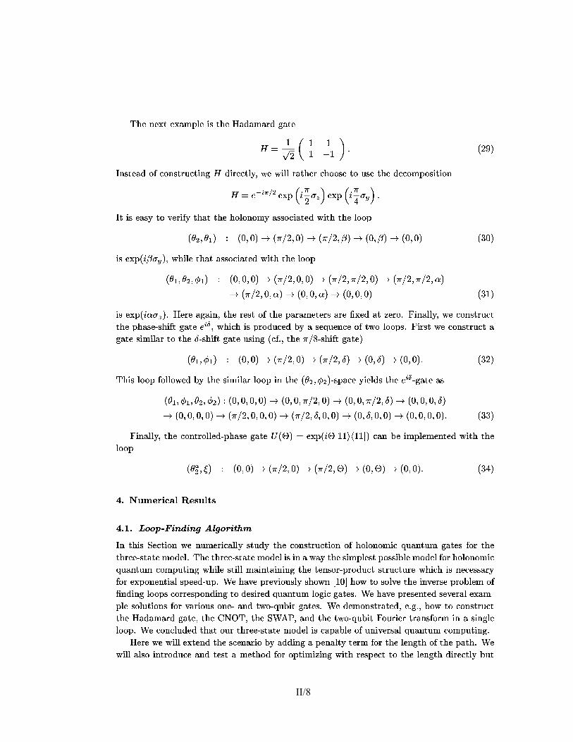
� �1�=����r¥u��l3�!nq�(��k ���il���l3w�l�p�l�l3�!��k � k ���,l�t ~�¢£l�l 5�7�9
��Ö�ÏHÛ@Ï ��ÒRÏ���Ü(ØQÙ@Ú&Ï�×&Ñ�Ò3Ö�ÏHè¿Ü�Ô0Ü�ØMÜ�á3Ô\ã!Ü�Ò3Ï
6 G ô� ø � ô ô
ô ��ô % v ê�øR,î
ÿqÛ�Ñ.Ò3Ï)Ü(ÔXÝ,Þbà)Ý,Û�Ñ.Ò¦á3Ó�à�Ò3×oÛ�ã@6 Ô�×¥á3Ï)à�Ò3Ú¥Õ!÷�ï�Ï¿ï£×oÚ&Ú�á�Ü�Ò3Ö�Ï�á£à�Ö�Ý�Ý(ѦÏ�Ò3ÝQÓ�ѦÏ�Ò3Ö�Ï�Ô@Ï�à�Ý,ØQÙ�Ý,ѦץÒ3×&Ý,Û
6 G:! N A ��� � Ï���Ù " D � ø���� $ Ï ��Ù " D � ú���� $ v
ÿsÒ£×&ÑRÏ)Ü(Ñ.ÕòÒ3Ý ö!Ï�á3×&ÞoÕMÒ3Ö@Ü�ÒRÒ3Ö�ÏHÖ�Ý,Ú&Ý,Û�Ý,Ø[ÕòÜ(ѦѦÝ�à�×oÜ�Ò3Ï)Ôòï£×¥Ò3ÖòÒ3Ö�Ï�Ú&Ý�Ý(Ù
ê ' � mA'a_�î � ê}��mf�!î � ê!���(øimh�|î � ê!�-�(ø m p�î � ê}��m p�î � ê}��mh�|î ê�ù2�!î
×&ÑRÏ ��Ù=ê D p���î�÷�ï£Ö@×&Ú&Ï¿Ò3Ö@Ü�Ò�Ü(ѦѦÝ|à)×oÜ�Ò3Ï�Ôòï£×¥Ò3ÖòÒ3Ö�Ï�Ú&Ý�Ý(Ù
ê 'a_�m<' � m<4b_�î � ê}��mh��mh�|î � ê!�-�(øimh��mh�|î � ê!�-�(ø m����(øimh�|î � ê!���(øim�-�(øimheiî� ê!�-�(ø mf��mheiî � ê}��mf�imfeiî�� ê}��mh��mf�!î ê�ù�ô�î
×&Ñ�Ï���Ù=ê D�e���î�ç£è?Ï�á3ÏFÜ(ã!Ü�×oÛ6÷0Ò3Ö@ÏHá3Ï)Ñ.Ò?Ý,Þ{Ò3Ö�Ï[Ù0Ü�á�Ü(ØQÏ�Ò3Ï�á3Ñ?Ü�á3Ï��B��Ï)Ô Ü�Òx��Ï�á3Ý�ç 6{×&Û@Ü(Ú&Ú¥Õ!÷@ï�ÏFà)Ý,Û�Ñ.Ò¦á3Ó�à�Ò
Ò3Ö�ÏHÙ@Ö0Ü�ѦÏ�äѦÖ�×&Þ1Ò?ã!Ü�Ò3ÏG!�A�(÷0ï£Ö�×oà�ÖZ×&Ñ£Ù�á3Ý�Ô�Ó�à)Ï�ÔZæ|ÕZÜâѦÏ)ß|Ó�Ï)Û�à�Ï[Ý,Þ{Òsï�ÝMÚ&Ý�Ý(Ù@Ñ�çT6{×¥á3Ñ.Ò�ï�Ï[à)Ý(Û@Ñ.Ò¦á3Ó�à�Ò¿Üã!Ü�Ò3ÏHѦ×&ØQ×oÚoÜ�á�Ò3ÝDÒ3Ö�Ï�q�äѦÖ�×&Þ1Ò£ã!Ü�Ò3Ï�Ó�Ѧ×oÛ�ãXêgà)Þ�ç&÷�Ò3Ö@Ï��-��þ�äѦÖ�×oÞoÒ£ã,Ü�Ò3Ï�î
ê 'a_�m�4�_�î � ê}��mf�!î � ê!���(øimh�|î � ê!�-�(ø mhq!î � ê}��m~q!î � ê}��mh�|îfv ê�ù,ø,î
��Ö�×&Ñ£Ú&Ý�Ý(Ù\Þ�Ý,Ú&Ú&Ý�ï�Ï�Ôòæ|ÕYÒ3Ö@Ï�Ѧ×&Øâ×&ÚoÜ�á�Ú&Ý�Ý(ÙX×&ÛòÒ3Ö�ÏQê ' � m<4 � î�äÑ.Ù#Ü�à)Ï¿Õ�×&Ï)Ú&Ô�Ñ�Ò3Ö@Ï�!�A��äã!Ü�Ò3ÏHÜ(Ñ
ê 'a_�m�4�_�m<' � m<4 � î � ê}��mh��mh��mf�!î � ê}�imf��m�-��øimf�!î � ê}�imf��m�-��øimhq!î�� ê}��mh��mf�imhq!î� ê}��mh��mf�imf�|î � ê!���(øimh��mf�imf�|î�� ê!�-�(ø mhqsmf��mh�|î � ê}��m~qLmh��mh�|î � ê}��mh��mh��mh�|îfv ê�ù,ù,î
6{×&Û@Ü(Ú&Ú&Õ,÷�Ò3Ö�ÏDà�Ý,Û!Ò¦á3Ý,Ú&Ú&Ï)Ô�ägÙ@Ö@Ü(Ñ¦Ï ã!Ü�Ò3Ï�Dê��î�G Ï ��Ù=ê D�@c§ô(ôsg�nqô,ôic î£à)Ü(ÛPæ�Ï ×oØDÙ@Ú&Ï)ØQÏ)Û!Ò3Ï�ÔZï£×¥Ò3Ö Ò3Ö�ÏÚ&Ý�Ý(Ù
ê ' �� mA>!î � ê}��mf�!î � ê!���(øimh�|î � ê!�-�(ø m �î � ê}��m �î � ê}��mh�|îfv ê�ù�ú|î
�=Å S Ëb+ &�È(Í�ÌR(O'��9& ��Ëb'oÇ��=Å�Ä0Å���� � � ��� #��� #� $�� � $ ��� "�� ÿqÛ Ò3Ö�×&Ñ@|Ï)à�Ò3×&Ý,ÛÐï�ÏòÛ|Ó�ØQÏ�á3×&à)Ü(Ú&Ú&ÕëÑ.Ò3Ó�Ô�ÕÐÒ3Ö�ÏYà�Ý,Û�Ñ.Ò¦á3Ó�à�Ò3×&Ý,Û Ý(ÞRÖ@Ý(ÚoÝ(Û@Ý(Øâ×&àYß!Ó0Ü�Û|Ò3Ó�Ø ã,Ü�Ò3Ï)ÑFÞ�Ý�á Ò3Ö�ÏÒ3Ö�á3Ï�Ï�äÑ.Ò�Ü�Ò3Ï�ØâÝ�Ô�Ï�Úgç`��Ö�Ï�Ò3Ö�á3Ï)Ï�äÑ.Ò�Ü�Ò3Ï�ØâÝ|Ô@Ï�Ú!×&Ñ=×&ÛFÜ�ï�Ü)Õ�Ò3Ö�Ï�Ѧ×&ØQÙ@Ú&Ï�Ñ.Ò=Ù�Ý,ѦѦץæ0Ú&Ï�ØQÝ�Ô�Ï)Ú,Þ�Ý(ábÖ�Ý,Ú&Ý,Û�Ý,ØQ×oàß|Ó@Ü(Û!Ò3Ó�Ø à)Ý(ØQÙ@Ó�Ò3×&Û@ãYï£Ö�×&Ú&ÏDÑ.Ò3×&Ú&Ú{ØâÜ(×&Û|Ò�Ü�×oÛ�×&Û�ãYÒ3Ö�ÏFÒ3Ï)Û�ѦÝ(á¦ägÙ�á3Ý�Ô�Ó�à�ÒHÑ.Ò¦á3Ó�à�Ò3Ó�á3Ï ï£Ö�×&à�Öë×&Ñ�Û�Ï�à)Ï�ѦÑ3Ü�á¦ÕÞ1Ý(áRÏ ��Ù�Ý,Û�Ï)Û!Ò3×oÜ(Ú#Ñ.Ù�Ï)Ï�Ô�äÓ�ÙdçiÎÐÏ¿Ö@Ü)ö,Ï¿Ù�á3Ï�ö�×&Ý,Ó�ѦڥÕMѦÖ�Ý�ï£ÛÐó§ô��(õ�Ö@Ý)ï¶Ò3Ý Ñ¦Ý,Ú¥ö!Ï?Ò3Ö�Ï?×oÛ!ö!Ï�á3ѦÏ?Ù�á3Ý(æ@Ú&Ï�ØéÝ,Þ�@Û�Ô�×oÛ�ã[Ú&Ý�Ý(Ù@Ñfà�Ý(á¦á3Ï�Ñ.Ù6Ý(Û@Ô�×&Û�ãHÒ3ÝHÔ@Ï�Ѧץá3Ï)ÔMß!Ó0Ü�Û|Ò3Ó�ØDäÚ&Ý,ã,×&àRã!Ü�Ò3Ï�Ñ�ç{ÎÐÏ£Ö0Ü�ö!Ï£Ù�á3Ï)ѦÏ�Û!Ò3Ï)ÔâѦÏ�ö,Ï�á�Ü(Ú@Ï ��Ü(ØDäÙ@Ú&ÏFѦÝ,Ú&Ó�Ò3×&Ý,Û�Ñ?Þ1Ý(á?ö(Ü�á3×&Ý,Ó�Ñ�Ý,Û�Ï�ä�Ü(Û�ÔZÒsï�Ý(ä�ß|Ó�æ@×&Ò?ã!Ü�Ò3Ï�Ñ�ç£ÎÐÏFÔ�Ï�ØâÝ(Û@Ñ.Ò¦á�Ü�Ò3Ï)Ô6÷�Ï(ç ã�ç&÷�Ö�Ý�ïOÒ3ÝMà)Ý,Û�Ñ.Ò¦á3Ó�à�ÒÒ3Ö�Ï[è¿Ü(Ô@Ü(ØâÜ�á3ÔZã,Ü�Ò3Ï,÷0Ò3Ö�Ï íl��1x�¿÷@Ò3Ö�Ï!!Îëå ��÷�Ü(Û�ÔXÒ3Ö�ÏHÒsï�Ý(ä�ß|Ó�æ@×¥Ò 6@Ý,Ó�á3×&Ï�á£Ò¦á�Ü(Û�ѦÞ�Ý(á3Ø ×oÛ ÜQѦ×&Û@ã(ÚoÏÚ&Ý�Ý(Ùdç{ÎÐÏHà�Ý,Û�à)Ú&Ó�Ô�Ï)ÔòÒ3Ö@Ü�Ò£Ý,Ó�áRÒ3Ö�á3Ï�Ï�äÑ.Ò�Ü�Ò3Ï�ØQÝ�Ô�Ï)Ú6×oÑRà)Ü�Ù0Ü�æ@Ú&Ï�Ý,ÞbÓ@Û�×¥ö!Ï�á3Ñ3Ü(Ú=ß|Ó@Ü(Û!Ò3Ó�Ø à�Ý,ØDÙ0Ó�Ò3×&Û�ã�ç
è?Ï�á3Ï�ï�Ï?ï£×&Ú&Ú#Ï ��Ò3Ï�Û@ÔMÒ3Ö�Ï?Ѧà)Ï�Û@Ü�á3×&ÝFæ|ÕYÜ(Ô�Ô@×&Û�ãDÜ[Ù�Ï)Û@Ü(Ú¥ÒsÕQÒ3Ï�á3Ø Þ1Ý(á�Ò3Ö�Ï?ÚoÏ�Û�ã(Ò3ÖYÝ,Þ6Ò3Ö@Ï�Ù0Ü�Ò3Ö6çiÎÐÏï£×&Ú&Ú�Ü(Ú&ѦÝY×&Û!Ò¦á3Ý�Ô�Ó@à�Ï Ü(Û�Ô Ò3Ï�Ñ.Ò�ÜMØQÏ�Ò3Ö�Ý�ÔZÞ�Ý(á¿Ý�Ù@Ò3×&ØQ×��)×&Û�ãQï£×¥Ò3ÖZá3Ï�Ñ.Ù6Ï�à�Ò?Ò3ÝMÒ3Ö�Ï Ú&Ï�Û@ã�Ò3Ö Ô�×¥á3Ï)à�Ò3Ú¥Õòæ0Ó�Ò
II/8

5�7�� ��¡,m�r�¢�l�t!w�~�t ~��!~3¢�roy��sÃ(l��,m�Ã�¢ ��l�mon.u
ï£×¥Ò3ÖMÜ�Ù�Ï�Û@Ü(Ú¥ÒsÕ Ò3Ï�á3Ø Ü�á3×&Ѧ×oÛ�ãHÔ�Ó�Ï£Ò3Ý[Ï ��à�Ï)ѦÑ�Ô@Ï�ö�×oÜ�Ò3×&Ý,ÛQÞoá3Ý,Ø Ò3Ö�Ï£Ô�Ï)Ѧץá3Ï�Ôâã!Ü�Ò3Ï(ç�ÿqÛâÒ3Ö�×&ÑfØâÜ(Û�Û�Ï�áfÝ,Û�ÏØâÜ)ÕYÏ �âà�×&Ï)Û!Ò3Ú¥ÕMà)Ý(ØFæ@×&Û�Ï¿Ú&Ý�Ý(Ù@Ñ�ç ��ö!Ï�ÛòÒ3Ö�Ý,Ó�ã,ÖYÒ3Ö�Ï)ѦϿØâÏ)Ü(ѦÓ�á3Ï)Ñ�ï£×&Ú&Ú�Û�Ý(Ò�á3Ï�ѦÓ@Ú¥ÒR×&ÛòÜ à�Ö@Ü(Û�ã,Ï�×&ÛYÒ3Ö�Ïß|Ó@Ü(Û!Ò3Ó�ØDäà)Ý,ØDÙ@Ó�Ò�Ü�Ò3×&Ý,Û@Ü(Ú#à�Ý,ØDÙ0Ú&Ï ��×¥ÒsÕ!÷|×¥Ò�ØâÜ)ÕQæ�Ï�Ù�Ý,ѦѦץæ@ÚoÏ£Ò3ÝFѦ×oã(Û@×X�@à)Ü(Û!Ò3Ú&ÕDá3Ï�Ô�Ó@à�Ï�Ò3Ö�Ï?Ø Ó�Ú¥Ò3×¥Ù@Úo×&Ï�á3Ñ×&Û Þ1á3Ý,Û!Ò[Ý,Þ²Ò3Ö�ÏQÖ@×&ã,Ö�Ï�Ñ.Ò¦äÝ(á3Ô�Ï�áHÒ3Ï�á3ØQÑH×oÛPÒ3Ö�ÏâÏ ��Ù�á3Ï)ѦѦ×&Ý,Û Þ�Ý(áHÒ3Ö�ÏYí ��� Ï���Ï)à�Ó�Ò3×oÝ(ÛPÒ3×oØQÏ(çQÿqÛÐÝ(Ò3Ö�Ï�áï�Ý(á3Ô�Ñ�÷0Ò3Ö�ÏHæ@×&ã(ä 1OÛ@Ý�Ò�Ü�Ò3×&Ý,ÛX×&ÑRÒ3Ö@ÏHÑ3Ü(ØQÏ,÷@æ@Ó�Ò�Û�Ï�ö!Ï�á¦Ò3Ö�Ï)Ú&Ï�ѦÑ�÷0ØFÓ@à�ÖZÝ,Þ�Ò3Ö�ÏHà)Ý,ØDÙ@Ó�Ò�Ü�Ò3×&Ý,ÛòÒ3×oØQÏ�ØMÜ)Õæ�Ï�Ñ3Ü)ö!Ï�Ôdç6{×¥á3Ñ.Ò�ï�Ï�á3Ï�ö�×&Ï�ï Ý,Ó�á�æ0Ü(Ѧ×&à£Ü(Ú&ã,Ý�á3×&Ò3Ö�ØKÜ(Û�ÔQѦÖ@Ý)ï»Ñ¦Ý(ØâÏ�Û�Ï�ï Ï���Ü�ØQÙ@Ú&Ï�ã!Ü�Ò3Ï�Ñ�ç?�¿Ü(ØQÏ)Ú¥Õ,÷,Ï)Ü(à�ÖDÚoÝ|Ý(Ù
� ×&ÛQÒ3Ö@Ï�Ù0Ü�á�Ü(ØQÏ�Ò3Ï�á²Ñ.Ù0Ü(à�Ï�à�Ý(á¦á3Ï�Ñ.Ù�Ý,Û�Ô@ÑfÒ3Ý[ÜHã!Ü�Ò3Ï � � ç{ÎÐÏRï£×&ѦÖâÒ3ÝHѦÝ,Ú¥ö!ÏRÒ3Ö�Ï£×&Û|ö,Ï�á3ѦÏRÙ�á3Ý(æ@Ú&Ï)Ø��|ÎÐÏÚ&Ý�Ý � Þ1Ý(á�Ü��� Ò3Ö@Ü�Ò²à�Ý(á¦á3Ï)Ñ.Ù�Ý,Û�Ô�ѲÒ3Ý ��Dç�Î Ï�Þ�Ó�á¦Ò3Ö�Ï�á²á3Ï)Ñ.Ò¦á3×&à�Ò²Ý,Ó�á3ѦÏ)Ú¥ö!Ï�ѲÒ3ÝHÒ3Ö�Ï�Ñ.Ù#Ü�à)Ï?Ý,ÞdÜ(Ú&Ú@Ù�Ý,Ú¥Õ�ã,Ý,Û@Ü(ÚÚ&Ý�Ý(Ù@Ñ�ç ÿqÞ��O×&Ñ¿Ò3Ö�ÏQÑ.Ù0Ü(à�ÏQÝ,Þ�Ü(Ú&Ú�Ù�Ý,ѦѦץæ0Ú&ÏDÚ&Ý�Ý(Ù@Ñ¿ï£×&Ò3ÖPÒ3Ö�ÏDã,×¥ö!Ï�Ûëæ0Ü(ѦÏDÙ�Ý,×&Û!Ò)÷dÒ3Ö�Ï)Û��bKMï£×&Ú&Ú�æ�ÏDÒ3Ö�ÏÑ.Ù0Ü(à�Ï[Ý,Þ{Ü(Ú&Ú�Ò3Ö@Ý(ѦÏ�Ù6Ý(Ú&Õ�ã,Ý,Û@Ü(ÚdÚ&Ý�Ý�Ù0Ñ�Ò3Ö@Ü�Ò£Ö@Ü)ö!Ï|MMö!Ï�á¦Ò3×&à�Ï)Ñ�×&ÛZÜ(Ô�Ô�×¥Ò3×oÝ(ÛòÒ3ÝDÒ3Ö@Ï�æ0Ü(ѦÏ�Ù�Ý,×&Û!Ò)çfè?Ï�á3ÏHÝ,Þà�Ý,Ó�á3ѦÏ��bK ���ç/��Ö�×oÑ�Ù�á3Ý(æ@ÚoÏ�Ø à)Ü(Û æ�Ï Þ�Ý�á3Ø Ó�ÚoÜ�Ò3Ï�ÔPÜ(Ñ¿Ü(ÛPÝ(Ù�Ò3×&Øâ×��)Ü�Ò3×&Ý,Û\Ù@á3Ý�æ0Ú&Ï�ØXç51�Û�Ï Û�Ï)Ï�Ô�Ñ¿Ò3Ý�@Û�Ô�� ѦÓ�à�ÖXÒ3Ö@Ü�Ò ê � î�G�� �� � � � �� ê�ù,û,î
×&Ñ¿ØQ×&Û�×oØQ×��)Ï�ÔXÝ�ö!Ï�áHÜ(Ú&Ú � =��bKQÎÐÏDÜ(×&Ø Ü�Ò?Ò3Ö�Ï ØQ×&Û�×oØFÓ�Ø ö,Ü(Ú&Ó�Ï[Ò3ÝMæ�Ï|�)Ï�á3Ý�ç�è?Ï�á3Ï������� ¼Ô�Ï�Û@Ý�Ò3Ï)ÑÒ3Ö�Ï 6@á3Ý(æ�Ï�Û�×oÓ�ÑRÛ@Ý�á3Ø Ô�Ï �0Û�Ï�ÔZÜ(Ñ�� " �� <G�� �=ábê " = " î�ç60Ý�áDÝ,Û�Ï�ä�ß|Ó�æ@×&Ò[ã!Ü�Ò3Ï�Ñ�÷�Ò3Ö@ÏâÔ�×oØQÏ�Û@Ѧ×&Ý,Û ×oÑ[ú Mëï£Ö�Ï�á3Ï�Ü�ÑF×&Û Ò3Ö�ÏMà)Ü(ѦÏMÝ,Þ�Òsï�Ý(ä�ß|Ó�æ@×¥ÒFã!Ü�Ò3Ï�Ñ[Ò3Ö�ÏMÔ�×¥äØQÏ)Û�Ѧ×&Ý,ÛÐ×&ÑyRM0çMÎ ÏâÓ�ѦÏ�ÔÐÒ3Ö�ÏDÙ�Ý,Ú¥Õ�Ò3Ý(Ù�ÏâÜ(Ú&ã,Ý(á3×¥Ò3Ö�Ø ó�ô�û�õ�Ò3ÝXѦÝ,Ú¥ö!ÏDÒ3Ö�×oÑ�Ù�á3Ý(æ@ÚoÏ�Ø\ç ��Ö@ÏQá3Ï)Ü(ѦÝ,ÛÐÞ�Ý�áÏ�ØQÙ@Ú&Ý�Õ�×&Û�ãMÒ3Ö@×&Ñ?ØâÏ�Ò3Ö�Ý�Ôë×&Ñ�Ò3Ö@Ï Ï��|Ò¦á3Ï)ØQÏ)Ú¥ÕXà�Ý,ØQÙ@Ú&×&à�Ü�Ò3Ï)Ô Ñ.Ò¦á3Ó�à�Ò3Ó�á3Ï Ý,Þ�Ò3Ö�ÏDÝ(æi�¦Ï�à�Ò3×¥ö!ÏFÞ�Ó�Û�à�Ò3×oÝ(ÛdçHÿqÛ6{×&ã�ç�ô?ï�Ï¿Ö@Ü)ö,Ï¿Ù@Ú&Ý(Ò¦Ò3Ï�ÔYÜQø�� ѦÏ)à�Ò3×&Ý,ÛYÝ,Þ6Ò3Ö@Ï?Þ�Ó�Û�à�Ò3×&Ý,Ûâö,Ü(Ú&Ó�Ï�Ñ�ç���Ö�×oÑl�@ã,Ó�á3Ï?ï�Ü�Ñ�Ý(æ�Ò�Ü(×&Û�Ï)ÔMæ|ÕMÓ@Ѧ×&Û�ãÒ3Ö�Ï¿Ú&×oÛ�Ï��¦Ý,×&Û�×&Û@ãFÒsï�Ý � Û�Ý�ï£ÛòØQ×&Û�×oØâÜ[Ý,Þ�Ü à�Ï�á¦Ò�Ü�×oÛYÝ,Û�Ï�ä�ß|Ó�æ0×¥Ò�ã!Ü�Ò3Ï�Ü(Ú&Ý,Û�ãFï£×&Ò3ÖòÜFá�Ü�Û@Ô�Ý,ØQÚ¥ÕMà�Ö�Ý,ѦÏ�ÛÙ�Ï�á¦Ù6Ï�Û�Ô�×oà�Ó�ÚoÜ�á£Ô�×¥á3Ï�à�Ò3×&Ý,Û6ç���Ö|Ó�Ñ£Ô�Ï�á3×&ö(Ü�Ò3×¥ö!Ï�ägæ0Ü(ѦÏ)ÔòØâÏ�Ò3Ö�Ý�Ô�Ñ£Ü�á3Ï�Û@Ý�Ò£Ï���Ù�Ï�à�Ò3Ï�ÔòÒ3Ý Ù6Ï�á3Þ�Ý�á3Øéï�Ï)Ú&Úgç
��Ö�Ï?à)Ü(Ú&à)Ó�ÚoÜ�Ò3×&Ý,ÛQÝ,Þ�Ò3Ö�Ï?Ö�Ý,Ú&Ý,Û�Ý,Ø[ÕDá3Ï)ß|Ó�×¥á3Ï)ÑfÏ�ö,Ü(Ú&Ó@Ü�Ò3×&Û�ã�Ò3Ö�Ï?Ý(á3Ô�Ï�á3Ï)ÔQÙ�á3Ý�Ô�Ó@à�Ò�×&Û �²ß@ç#ê¦ô��|î�çP��Ö�ÏØQÏ�Ò3Ö�Ý�ÔëÓ�ѦÏ)ÔÐ×&ÛëÒ3Ö�ÏâÛ|Ó�ØQÏ�á3×&à)Ü(Ú�Ü(Ú&ã,Ý(á3×¥Ò3Ö�Ø ×&Ñ�Ò3ÝXѦ×&ØDÙ0Ú¥ÕZïRá3×&Ò3Ï Ò3Ö@ÏDÝ(á3Ô�Ï�á3Ï�Ô Ù�á3Ý�Ô�Ó�à�ÒH×&Û Ü �0Û�×¥Ò3Ï�äÔ�×Xz�Ï�á3Ï�Û�à)Ï�Ü�Ù�Ù�á3Ý7��×&ØâÜ�Ò3×&Ý,ÛMæ|ÕYà)Ý,Û�Ѧ×&Ô�Ï�á3×&Û�ã Ò3Ö�Ï¿à�Ý,Û�Û@Ï�à�Ò3×oÝ(Ûòà)Ý,ØDÙ�Ý,Û�Ï)Û!Ò3ÑRÜ�Ñ�æ�Ï�×oÛ�ã à)Ý,Û�Ñ.Ò�Ü(Û!ÒRÝ�ö!Ï�á£ÜѦØâÜ(Ú&ÚdÔ�×Xz�Ï�á3Ï�Û�à)Ï�×&ÛòÒ3Ö�Ï�Ù0Ü�á�Ü�ØâÏ�Ò3Ï�á3Ñ0q � A ç60Ý�á£×oÛ�Ñ.Ò�Ü(Û�à�Ï,÷�ï�Ï�Ü�Ò¦Ò3Ï)ØDÙ�Ò3Ï)ÔYÒ3Ý|�@Û�ÔXÜDÚ&Ý�Ý�Ù\à)Ý(á¦á3Ï�Ñ.Ù�Ý,Û�Ô�×oÛ�ã Ò3Ý Ò3Ö�Ï�è¿Ü(Ô@Ü(ØâÜ�á3Ôòã!Ü�Ò3Ï(çiÎÐÏ�Ö@Ü)ö,ÏÙ�á3Ï�ö�×&Ý,Ó�ѦÚ&Õâã,×¥ö!Ï�Û\ÜFÔ�×�z�Ï�á3Ï)Û!Ò�×oØDÙ@Ú&Ï)ØQÏ)Û!Ò�Ü�Ò3×&Ý,ÛâÝ,ÞdÒ3Ö�×&Ñ�ã!Ü�Ò3Ïâó§ô���õgç���Ö@Ï�á3Ï)ѦÓ�Ú¥Ò3×&Û�ã Ú&Ý�Ý(Ùò×&Ñ�×oÚ&Ú&Ó�Ñ.Ò¦á�Ü�Ò3Ï�Ô×&Û 6�×oã�çiø�ç-�?Ý�Ò3ÏMÒ3Ö@Ü�Ò[Ò3Ö@×&ÑFÝ�Ù@Ò3×&ØQ×���Ü�Ò3×&Ý,Ûëï�Ü(Ñ à)Ü�á¦á3×&Ï�Ô Ý,Ó�Ò ×&Û��7�âØâÏ)Ü(Û�×&Û@ãXÒ3Ö@Ü�ÒFÒ3Ö�Ï�á3ÏYÜ�á3ÏâÒ3Ö�á3Ï�Ïö!Ï�á¦Ò3×&à)Ï�Ñ�Ý(Ò3Ö�Ï�á?Ò3Ö@Ü(ÛXÒ3Ö�Ï[á3Ï)Þ1Ï�á3Ï�Û�à)ÏHÙ�Ý,×&Û!Ò)çRÎÐÏFÖ@Ü)ö!Ï[Ò�Ü � Ï�ÛZÒ3Ö�Ï[Ý(á3×&ã,×&ÛXÒ3ÝMæ�ÏHÒ3Ö�×&Ñ�á3Ï�Þ�Ï�á3Ï)Û�à�ÏHÙ6Ý(×oÛ!Ò)ç��Ö�Ï�ÚoÏ�Û�ã(Ò3ÖâÝ,Þ�Ò3Ö�×&ÑfÏ ��Ü(ØDÙ0Ú&Ï£Ú&Ý�Ý(ÙM×&Ñ�ô�ø�ç ��ô�×&ÛQÒ3Ö@Ï �fÓ�à)Ú&×&Ô�Ï�Ü(ÛâÜ�Ù�Ù�á3Ý7��×&ØâÜ�Ò3×&Ý,Û6çP�bÝ[ã,×¥ö!Ï�Ü(ÛMÏ ��Ü(ØDÙ@ÚoÏÝ,ÞfÜMÒsï�Ý(ä�ß!Ó�æ@×¥Ò�ã,Ü�Ò3Ï,÷#ï�ÏDÖ@Ü)ö!Ï ×oÛ�à�Ú&Ó@Ô�Ï�Ô ×oÛO6{×&ã�çdùYÜMÚ&Ý�Ý(ÙPÒ3Ö@Ü�Ò?Õ�×&Ï)Ú&Ô�Ñ�Ò3Ö�ÏFï�Ï�Ú&Ú&ä � Û@Ý)ï£Û Òsï�Ý(ä�ß|Ó�æ@×¥Òß|Ó@Ü(Û!Ò3Ó�Ø ö!Ï�á3Ѧ×&Ý,Û Ý,Þ�Ò3Ö�Ï?60Ý(Ó�á3×&Ï�áâÒ¦á�Ü(Û�ѦÞ�Ý(á3Ø\ç ��Ö@×&ÑQÚ&Ý�Ý(Ù¼×&ÑMÜ(ã,Ü(×&Û¼Ô�×Xz�Ï�á3Ï�Û!ÒMÞoá3Ý,Ø Ò3Ö�ÏXÏ ��Ü(ØDÙ@ÚoÏѦÝ,Ú&Ó�Ò3×&Ý,Û�ÑHÝ,Þ�ñ£Ï�Þsç²ó�ô���õgç ��Ö|Ó�Ñ[Ý,Û�Ïâ×&ÑHà�Ý,Û!ö�×&Û�à)Ï�ÔëÒ3Ö@Ü�ÒHÒ3Ö�ÏQѦÝ,Ú&Ó�Ò3×&Ý,Ûë×&Ñ�æ|ÕëÛ@Ý\ØâÏ)Ü(Û�ÑHÓ�Û@×oß|Ó�Ï(çF6@Ý(á×&Û�Ñ.Ò�Ü(Û�à)Ï(÷|Ò3Ö�ÏRѦÝ,Ú&Ó�Ò3×&Ý,ÛâÔ�Ï�Ù�Ï)Û�Ô�ÑfÑ.Ò¦á3Ý,Û�ã,Ú¥ÕQÝ(ÛQÒ3Ö@Ï£×&Û�×¥Ò3×1Ü�Ú@à�Ý,Û��@ã,Ó�á�Ü�Ò3×&Ý,ÛâÝ,Þ#Ò3Ö�Ï£Ù�Ý,Ú¥Õ�Ò3Ý�Ù6Ï£Ü�Úoã(Ý(á3×¥Ò3Ö@Ø\çè?Ï�Û�à)Ï(÷�Ò3Ö�Ï�á3ÏH×&Ñ£Ü(ØDÙ@ÚoÏ¿ØâÝ(Ò3×¥ö(Ü�Ò3×&Ý,ÛMÒ3ÝQѦÏ�Ü�á3à�ÖXÞ1Ý(á£Ñ¦Ö�Ý(á¦Ò3Ï�á£ÚoÝ|Ý(Ù@Ñ�ç
�bÝDѦÖ�Ý�ï ØQÝ(á3Ï¿à)Ú&Ï)Ü�á3Ú¥ÕâÒ3Ö�Ï?Ù�Ý�ï�Ï�áRÝ,ÞbÝ,Ó�á�Ò3Ï)à�Ö�Û�×1ß!Ó@Ï(÷�ï�Ï�Ö@Ü)ö,Ï¿Ù@ÚoÝ�Ò¦Ò3Ï)Ôò×&Û86{×&ã�ç�ú Ò3Ö�Ï�Ï�á¦á3Ý(á£Ü(ÑRÜÞ1Ó@Û�à�Ò3×&Ý,ÛYÝ,Þ=Þ1Ó�Û@à�Ò3×&Ý,ÛYÏ�ö,Ü�ÚoÓ@Ü�Ò3×&Ý,Û�ѲÞ1Ý(á�Ò3Ö�á3Ï�Ï¿×&Û�Ô@Ï�Ù�Ï)Û�Ô�Ï�Û|Ò²á3Ó�Û@Ñ�ç���Ö�Ï¿Ü�Ò¦Ò3Ï)ØDÙ�Ò3Ï)ÔMÚ&Ý,ã,×&à)Ü(Ú#Ý�Ù6Ï�á�Ü�Ò3×&Ý,Ûï�Ü(ÑHÒ3Ö�Ïâè¿Ü(Ô@Ü(ØâÜ�á3Ô ã!Ü�Ò3Ï(çMÎÐÏQѦÏ)ÏQÒ3Ö@Ü�ÒHÒ3Ö@ÏQà�Ý,Û!ö!Ï�á3ã(Ï)Û�à�ÏâѦÏ)Ï�ØâÑ�Ò3Ý\æ�ÏâÏ��|Ù6Ý(Û@Ï�Û!Ò3×oÜ(Úgç9� Ý(á3Ï�Ý�ö!Ï�á)÷Ü\Þ�Ï�ï Ö|Ó�Û�Ô�á3Ï)ÔÐÏ�ö(Ü(Ú&Ó@Ü�Ò3×&Ý,Û�ÑHÝ(Þ ê � î?×&ÑHÏ�Û@Ý(Ó@ã(Ö Ò3ÝZÜ(à�Ö�×oÏ�ö!ÏâÜ�ÛÐÏ�á¦á3Ý�áFÜ(Ñ[Ú&Ý�ï Ü(Ñâô�� N � çQÎÐÏMÜ�á3ã,Ó�ÏÒ3Ö@Ü�Ò{Ý,Û�Ï�à)Ü(Û Ü(à�Ö@×&Ï�ö!Ï�Ü�á¦æ0×¥Ò¦á�Ü�á3×&Ú¥Õ�ѦØMÜ�ÚoÚ|Ï�á¦á3Ý(á3Ñ�æ|ÕHá3Ó�Û�Û@×&Û�ã�Ò3Ö�Ï�Ü(Ú&ã,Ý�á3×&Ò3Ö�Ø Ú&Ý,Û�ã?Ï�Û�Ý,Ó�ã,Ö6ç?�?Ó�ØâÏ�á3×&à�Ü�Úá3Ý,Ó�Û�Ô�×&Û@ã¿Ï�á¦á3Ý(á3Ñ�ï£×oÚ&Úg÷�Ò3Ö@Ý(Ó@ã(Öd÷,à�Ý,ØDÙ0Ú&×&à)Ü�Ò3ÏfÒ3Ö�×&Û�ã,Ñ{ѦÚ&×&ã,Ö!Ò3Ú¥Õ!ç=ÿsÒi×&Ñ{×&ØQÙ�Ý(á¦Ò�Ü�Û|Ò�Þ1á3Ý,ØOÒ3Ö�Ï�Ï��|Ù6Ï�á3×&ØâÏ�Û!Ò�Ü(ÚÙ�Ý,×&Û!Ò£Ý,Þbö�×oÏ�ï �¦Ó�Ñ.ÒRÒ3ÝâÜ(à�Ö�×oÏ�ö!Ï�Ú&Ý�ï Ï)Û�Ý,Ó�ã,Ö\Ï�á¦á3Ý(á3Ñ�ç
II/9

� �1�=����r¥u��l3�!nq�(��k ���il���l3w�l�p�l�l3�!��k � k ���,l�t ~�¢£l�l 5�7��
¸���º�% ��%�'��ë-s���AA�´oA+.-q�� ���£�����±�+��3'¦´1�����+.��Ag��������$!����g+.-s�� ¬�+{������-s������!%
II/10

5�9�2 ��¡,m�r�¢�l�t!w�~�t ~��!~3¢�roy��sÃ(l��,m�Ã�¢ ��l�mon.u
0 0.5 1 1.5 20
0.2
0.4
0.6
0.8
1
1.2
1.4
1.6
0 0.5 1 1.5 2−1.5
−1
−0.5
0
0.5
1
1.5
2
0 0.5 1 1.5 2−2.5
−2
−1.5
−1
−0.5
0
0.5
1
1.5
2
���������
��� ��� � �
¸�� º�%,'�%0«��)���¿�����±�+{��������+q�+q�6Ag����-.+{�±����d�����$ +.�+.���A��±�+i�������������£º����+�·=� �±=/�� �²4�� �¦'�� 2 ��%
−2.5 −2 −1.5 −1 −0.5 0−1
−0.5
0
0.5
1
����
� ���
−2.5 −2 −1.5 −1 −0.5 0−2
−1
0
1
2
3
4
5
����
� ���
−2.5 −2 −1.5 −1 −0.5 0−4
−3
−2
−1
0
1
2
3
4
����
� � �
−2.5 −2 −1.5 −1 −0.5 0−2
−1.5
−1
−0.5
0
0.5
1
����
�� �
−2.5 −2 −1.5 −1 −0.5 0−1.5
−1
−0.5
0
0.5
1
1.5
2
2.5
����
�� �
−2.5 −2 −1.5 −1 −0.5 0−1
0
1
2
3
4
5
6
����
�� �
−2.5 −2 −1.5 −1 −0.5 0−2
−1
0
1
2
3
4
����
�� �
−2.5 −2 −1.5 −1 −0.5 00
2
4
6
8
10
12
����
�
¸�� º�%�®�% «��)�������! #"!$&% '($F���P�±�+Q�������R+s�+q�[A�����-q+Q�±����Fº�� ¬�+.AH�±�+Q��·6��´1µ����� � ¸��������+s� º����+�%K��+q�+=/����) #"!$&% '*$s4��X7�®+� ®�5�%@c=±�+i+q�g����d·6��Ad,+.$ �¦· �q2-,/.�0�%
II/11
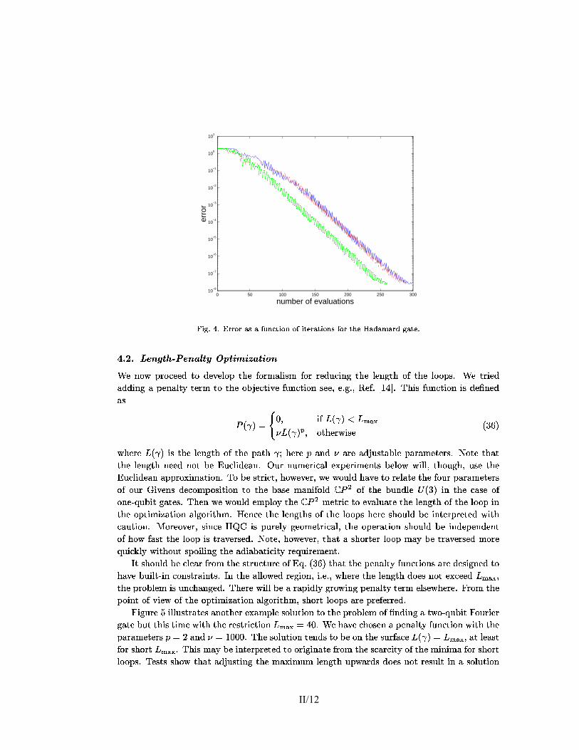
� �1�=����r¥u��l3�!nq�(��k ���il���l3w�l�p�l�l3�!��k � k ���,l�t ~�¢£l�l 5�9 �
0 50 100 150 200 250 30010
−8
10−7
10−6
10−5
10−4
10−3
10−2
10−1
100
101
number of evaluations
erro
r
¸���º�%@��%0j@�g����=��A=��������-s������¿����� �+q����������Ad�����d�±�+i�b������R�����º����+�%
�=Å)"�Å�� ��� $ "������ ��� %�� "�� � ��" �� %&" &� �ÎÐÏ\Û�Ý�ï Ù�á3Ý�à�Ï)Ï�Ô¾Ò3ÝëÔ�Ï�ö!Ï�Ú&Ý(Ù¾Ò3Ö@ÏòÞ�Ý(á3ØâÜ(Ú&×&Ñ¦Ø Þ1Ý(áQá3Ï�Ô�Ó@à�×&Û�ãPÒ3Ö@ÏòÚ&Ï)Û�ã(Ò3Ö¾Ý,Þ£Ò3Ö�Ï\Ú&Ý�Ý(Ù@Ñ�ç ÎÐÏòÒ¦á3×&Ï)ÔÜ(Ô�Ô�×&Û�ã\ÜâÙ�Ï)Û@Ü(Ú¥ÒsÕ\Ò3Ï�á3Ø Ò3ÝMÒ3Ö�Ï Ý(æi�¦Ï�à�Ò3×¥ö!ÏFÞ1Ó�Û@à�Ò3×&Ý,Û Ñ¦Ï)Ï(÷6Ï(ç ã�ç¥÷dñ£Ï�Þsçió�ô�ú(õç/��Ö@×&Ñ?Þ�Ó�Û�à�Ò3×&Ý,ÛZ×oÑ?Ô�Ï��@Û�Ï)ÔÜ(Ñ
�Qê � îPG� �im ×&Þ �£ê � î�� ���� �£ê � î���mVÝ(Ò3Ö�Ï�á¦ï£×oÑ¦Ï ê�ù,ü,î
ï£Ö�Ï�á3Ï �Rê � î�×&Ñ¿Ò3Ö�ÏDÚ&Ï)Û�ã(Ò3ÖPÝ,Þ�Ò3Ö�ÏDÙ0Ü�Ò3Ö � �bÖ�Ï�á3Ï��ÐÜ(Û�Ô Ü�á3ÏâÜ�ÔL�.Ó�Ñ.Ò�Ü�æ@ÚoÏFÙ0Ü�á�Ü(ØQÏ�Ò3Ï�á3Ñ�ç|�?Ý(Ò3ÏFÒ3Ö0Ü�ÒÒ3Ö�ÏMÚ&Ï)Û�ã(Ò3ÖÐÛ�Ï)Ï�Ô Û�Ý(ÒFæ�Ï �fÓ�à)Ú&×&Ô�Ï�Ü(Û6ç 1�Ó�áFÛ�Ó�ØQÏ�á3×&à)Ü(ÚfÏ ��Ù�Ï�á3×&ØQÏ)Û!Ò3ÑHæ�Ï)Ú&Ý�ï ï£×&Ú&Úg÷bÒ3Ö�Ý,Ó�ã,Ö6÷iÓ�ѦÏMÒ3Ö�Ï�fÓ�à�Ú&×oÔ�Ï)Ü(ÛYÜ�Ù@Ù�á3Ý7��×oØâÜ�Ò3×&Ý,Û6çP�=Ý[æ�Ï�Ñ.Ò¦á3×&à�Ò)÷|Ö�Ý�ï�Ï�ö,Ï�á)÷|ï�Ï£ï�Ý,Ó�ÚoÔMÖ@Ü)ö!Ï£Ò3ÝHá3Ï)ÚoÜ�Ò3ÏRÒ3Ö�Ï�Þ1Ý,Ó�á²Ù#Ü�á�Ü(ØâÏ�Ò3Ï�á3ÑÝ,Þ�Ý,Ó�á8�?×&ö,Ï)Û�ÑQÔ�Ï�à)Ý,ØDÙ�Ý,ѦץÒ3×&Ý,Û Ò3ÝëÒ3Ö�Ïòæ0Ü(ѦÏXØâÜ(Û�×&Þ�Ý,Ú&Ô ��� � Ý,Þ£Ò3Ö�Ï\æ@Ó�Û�Ô�ÚoÏ � ê�ù!îF×&Û¾Ò3Ö�Ï\à)Ü(ѦÏXÝ,ÞÝ,Û�Ï�ä�ß|Ó�æ@×&Ò�ã!Ü�Ò3Ï)Ñ�ç���Ö�Ï�ÛYï�Ï�ï�Ý,Ó�Ú&ÔòÏ�ØQÙ@Ú&Ý�ÕQÒ3Ö�Ï������[ØQÏ�Ò¦á3×&à£Ò3Ý Ï�ö,Ü�ÚoÓ@Ü�Ò3Ï£Ò3Ö�Ï?Ú&Ï)Û�ã(Ò3ÖYÝ(ÞdÒ3Ö�Ï?ÚoÝ|Ý(Ùò×&ÛÒ3Ö�ÏDÝ�Ù@Ò3×&ØQ×���Ü�Ò3×&Ý,Û Ü�Úoã(Ý(á3×¥Ò3Ö@Ø\ç�è?Ï)Û�à�ÏFÒ3Ö�Ï ÚoÏ�Û�ã(Ò3Ö�Ñ¿Ý,ÞiÒ3Ö@Ï Ú&Ý�Ý�Ù0Ñ¿Ö�Ï�á3Ï Ñ¦Ö@Ý(Ó@Ú&Ô æ�ÏD×&Û!Ò3Ï�á¦Ù�á3Ï�Ò3Ï)Ô ï£×¥Ò3Öà)Ü(Ó�Ò3×&Ý,Û6ç{� Ý(á3Ï)Ý)ö!Ï�á)÷{Ѧ×oÛ�à�ÏMèHìHíK×&Ñ[Ù@Ó�á3Ï�Ú&Õ ã(Ï)Ý,ØQÏ�Ò¦á3×oà)Ü(Úg÷=Ò3Ö@ÏMÝ(Ù�Ï�á�Ü�Ò3×&Ý,ÛÐѦÖ@Ý(Ó@Ú&ÔÐæ6ÏM×&Û�Ô�Ï�Ù�Ï�Û@Ô�Ï�Û!ÒÝ,Þ{Ö�Ý�ïOÞ�Ü(Ñ.Ò£Ò3Ö�Ï[ÚoÝ|Ý(Ù ×&ÑRÒ¦á�Ü)ö!Ï�á3ѦÏ�Ôdç0�?Ý(Ò3Ï,÷0Ö�Ý�ï�Ï�ö!Ï�á)÷0Ò3Ö@Ü�Ò?ÜQѦÖ@Ý�á¦Ò3Ï�á?Ú&Ý�Ý�Ù ØâÜ)Õòæ�ÏHÒ¦á�Ü)ö!Ï�á3ѦÏ)ÔZØQÝ(á3Ïß|Ó�×&à � Ú¥ÕMï£×¥Ò3Ö�Ý,Ó�Ò£Ñ.Ù�Ý,×&Ú&×&Û@ã Ò3Ö�ÏHÜ(Ô�×1Ü�æ#Ü�Ò3×oà�×¥ÒsÕâá3Ï�ß!Ó@×¥á3Ï�ØâÏ�Û!Ò)ç
ÿsÒfѦÖ�Ý,Ó�Ú&ÔQæ�ÏRà�Ú&Ï�Ü�á�Þoá3Ý,Ø Ò3Ö@ÏRÑ.Ò¦á3Ó�à�Ò3Ó�á3ÏRÝ,Þ �²ß0ç@ê�ù(ü!îbÒ3Ö@Ü�ÒiÒ3Ö�Ï�Ù�Ï)Û@Ü(Ú¥ÒsÕ Þ1Ó�Û@à�Ò3×&Ý,Û�ÑfÜ�á3ÏRÔ�Ï�Ѧ×&ã,Û�Ï)ÔDÒ3ÝÖ@Ü)ö!Ï�æ@Ó@×&Ú¥Ò¦ä×&Û\à�Ý,Û�Ñ.Ò¦á�Ü(×&Û!Ò3Ñ�ç�ÿqÛ\Ò3Ö�ÏHÜ(Ú&ÚoÝ)ï�Ï)Ôòá3Ï�ã,×&Ý,Û6÷@×gç Ï(ç&÷�ï£Ö�Ï�á3Ï¿Ò3Ö�ÏHÚ&Ï)Û�ã(Ò3ÖòÔ@Ý|Ï)ÑRÛ@Ý�Ò�Ï ��à)Ï�Ï�Ô ����|÷Ò3Ö�Ï£Ù�á3Ý(æ@Ú&Ï)Ø ×&ÑfÓ�Û�à�Ö@Ü(Û�ã,Ï�Ô6ç���Ö�Ï�á3Ï£ï£×&Ú&Ú�æ�Ï?Ü�á�Ü�Ù@×oÔ�Ú¥ÕDã(á3Ý�ï£×&Û�ãHÙ�Ï)Û@Ü(Ú¥ÒsÕ Ò3Ï�á3Ø Ï�Ú&ѦÏ�ï£Ö�Ï�á3Ï,ç-6�á3Ý,Ø Ò3Ö�ÏÙ�Ý,×&Û!Ò£Ý,Þbö�×oÏ�ï Ý,ÞbÒ3Ö�Ï�Ý(Ù�Ò3×oØQ×���Ü�Ò3×oÝ(Û\Ü(Ú&ã,Ý�á3×&Ò3Ö�Ø\÷�ѦÖ�Ý(á¦Ò£Ú&Ý�Ý�Ù0Ñ£Ü�á3Ï�Ù�á3Ï�Þ�Ï�á¦á3Ï)Ô6ç6{×&ã,Ó�á3Ï�û�×oÚ&Ú&Ó�Ñ.Ò¦á�Ü�Ò3Ï�ÑiÜ(Û�Ý(Ò3Ö�Ï�á�Ï ��Ü(ØDÙ@Ú&Ï�ѦÝ(ÚoÓ�Ò3×&Ý,ÛFÒ3Ý¿Ò3Ö�Ï�Ù�á3Ý(æ@ÚoÏ�Ø Ý,Þ �@Û�Ô�×&Û@ã�Ü?Òsï�Ý(ä�ß|Ó�æ@×¥Ò�60Ý,Ó�á3×&Ï�á
ã!Ü�Ò3Ï�æ@Ó�Ò{Ò3Ö@×&ÑbÒ3×&ØâÏfï£×¥Ò3ÖFÒ3Ö�ϲá3Ï)Ñ.Ò¦á3×&à�Ò3×&Ý,Û ������G<úa��ç�ÎÐÏ�Ö0Ü�ö!Ï�à�Ö@Ý(ѦÏ)ÛDÜ�Ù�Ï)Û@Ü(Ú¥ÒsÕ[Þ1Ó@Û�à�Ò3×&Ý,ÛFï£×¥Ò3ÖFÒ3Ö�ÏÙ0Ü�á�Ü(ØQÏ�Ò3Ï�á3Ñ���G¶ø?Ü(Û�Ô GOô��2�R��çP��Ö�Ï�ѦÝ(ÚoÓ�Ò3×&Ý,ÛFÒ3Ï�Û�Ô@Ñ�Ò3Ý?æ�Ï�Ý(Û Ò3Ö�Ï�ѦÓ�á3Þ�Ü(à�Ï1�£ê � îPG*����|÷!Ü�ÒiÚ&Ï�Ü�Ñ.ÒÞ1Ý(áfѦÖ�Ý(á¦Ò �����|çP��Ö�×oÑiØâÜ)ÕFæ�ÏR×&Û!Ò3Ï�á¦Ù�á3Ï�Ò3Ï)ÔFÒ3ÝHÝ�á3×oã(×oÛ@Ü�Ò3Ï�Þoá3Ý,ØKÒ3Ö�Ï�Ѧà�Ü�á3à)×¥ÒsÕ Ý,Þ@Ò3Ö�ÏRØâ×&Û�×&ØMÜ�Þ�Ý(á�ѦÖ�Ý(á¦ÒÚ&Ý�Ý(Ù@Ñ�ç��bÏ�Ñ.Ò3Ñ�ѦÖ�Ý�ï Ò3Ö@Ü�Ò?Ü(Ôs�¦Ó�Ñ.Ò3×&Û@ãQÒ3Ö�ÏHØMÜL��×oØFÓ�Ø Ú&Ï�Û�ã(Ò3ÖZÓ�Ù|ï�Ü�á3Ô�Ñ?Ô�Ý�Ï�Ñ�Û�Ý(Ò£á3Ï)ѦÓ�Ú¥Ò�×oÛZÜâѦÝ(ÚoÓ�Ò3×&Ý,Û
II/12

5�9�' ��¡,m�r�¢�l�t!w�~�t ~��!~3¢�roy��sÃ(l��,m�Ã�¢ ��l�mon.u
ö!Ï�á¦ÕMÛ�Ï�Ü�á�Ò3ÝFÒ3Ö�Ï?æ�Ý,Ó�Û�Ô0Ü�á¦Õâæ0Ó�Ò�á�Ü�Ò3Ö@Ï�áRÜFѦÝ,Ú&Ó�Ò3×oÝ(Ûò×&Ñ�Þ�Ý,Ó�Û�Ôò×&ÛMÒ3Ö�Ï¿ØQ×&Ô@Ô�Ú&Ï?Ý,ÞdÒ3Ö�Ï�ö!Ý,Ú&Ó�ØâÏ(ç�1?Û�Ï¿×&Ñ×&Û�à)Ú&×&Û�Ï)ÔYÒ3ÝâÔ�Ï�Ô�Ó@à�Ï[Þoá3Ý,Ø Ü(Ú&Ú6Ò3Ö�×&ÑRÒ3Ö@Ü�Ò£Ò3Ö�ÏHÛ|Ó�ØFæ�Ï�á�Ý,Þ�ѦÝ,Ú&Ó�Ò3×&Ý,Û�ÑRÒ3ÝDÒ3Ö�ÏHØQ×&Û@×&ØQ×���Ü�Ò3×&Ý,ÛMÙ�á3Ý(æ@Ú&Ï)Ø ×&ÑÖ|Ó�ã,Ï(çx��Ö�×&Ñ£Ù#Ü�á¦Ò3×oà�Ó�ÚoÜ�á?Ú&Ý�Ý(Ù ×&Ñ�ѦÖ@Ý�á¦Ò3Ï�á�Ò3Ö@Ü(Û Ý,Ó�á¿Ï)Ü�á3Ú&×&Ï�á�à�Ý,Û�Ñ.Ò¦á3Ó@à�Ò3×&Ý,Û6÷0æ@Ó�Ò¿Û�Ý(Ò?ØFÓ@à�Ö6ç�è?Ý�ï�Ï�ö!Ï�á)÷Ý,Ó�áx��á3Ñ.Ò�Ï ��Ü(ØDÙ@ÚoÏ[×oÛO6{×&ã�çdùâÖ@Ü(ÔëÜMÚoÝ|Ý(ÙPÚoÏ�Û�ã(Ò3Ö Ý,Þ²ü(ù�ç§ù,û|÷dѦÓ�à�ÖPÒ3Ö@Ü�Ò�Üâá3Ï)ØâÜ�á � Ü�æ@Ú&ÏF×&ØQÙ�á3Ý�ö!Ï�ØQÏ)Û!ÒÖ@Ü(ÑRæ�Ï)Ï�ÛXÜ(à�Ö@×&Ï�ö!Ï�Ôdç
−1 −0.5 0 0.5 1 1.5−1
−0.5
0
0.5
1
1.5
����
� ���
−1 −0.5 0 0.5 1 1.5−1.5
−1
−0.5
0
0.5
1
1.5
����
��
−1 −0.5 0 0.5 1 1.5−1.5
−1
−0.5
0
0.5
1
1.5
� ��
� �
−1 −0.5 0 0.5 1 1.5−2
−1.5
−1
−0.5
0
0.5
1
1.5
2
� ��
��
−1 −0.5 0 0.5 1 1.50
0.5
1
1.5
����
�� �
−1 −0.5 0 0.5 1 1.5−1
−0.5
0
0.5
1
1.5
2
����
�
−1 −0.5 0 0.5 1 1.5−1
−0.5
0
0.5
1
1.5
2
� ��
� �
−1 −0.5 0 0.5 1 1.5−3
−2
−1
0
1
2
3
4
� ��
�
¸�� º�%)5�%@«�+q��º��±�´o��������� ³.+.��$ �)���������@�±�+dµ���������� ¸������� +q�@�g�����Ag�����ë���� .�� %���+s�+ b/����) #"!$&% '*$�4��\® ��� ��7�����?�±�+i+s�g����=� Ad,+.$ �¦· �q2 ,�. 0 ·=� �±�'�2�2���� A-s�+q���³q���� ���£�!�������Ad�,+q�=+.��º�+�%
åKØQÝ(á3Ï[×&ØDÙ@á3Ï�ѦѦץö!Ï�á3Ï�Ô@Ó�à�Ò3×&Ý,ÛZÝ(ÞiÚ&Ï�Û@ã�Ò3ÖXØMÜ�Õ\æ�Ï[ѦÏ�Ï)ÛZ×&Û?6{×&ã�ç�ü�ç�Î Ï[Ö@Ü)ö!ÏHÙ�á3Ï�ö�×&Ý,Ó�ѦÚ&ÕòѦÖ�Ý�ï£Ûó§ô��(õdÜ(Ûò×oØDÙ@Ú&Ï)ØQÏ)Û!Ò�Ü�Ò3×&Ý,ÛâÝ,ÞdÒ3Ö@Ï5!Îëå � ã!Ü�Ò3Ï?Ò3Ö@Ü�Ò�Ö0Ü�ÔXÜ Ú&Ï)Û�ã(Ò3ÖYÝ,Þfô��|ý|ç�þ,û�ç���Ö�Ï¿ã!Ü�Ò3Ï¿ã,×¥ö!Ï�ÛYæ�Ï�ÚoÝ)ïÖ@Ü(Ñ�ÜDÚ&Ï�Û@ã�Ò3Ö\Ý,Þd�¦Ó�Ñ.Ò¿øR v R�çiÎÐÏ�ØMÜ�Û0Ü�ã,Ï)ÔòÒ3ÝQà�Ó�Ò£Ý2zëÜDØâÜs�.Ý(áRá3Ï�Ô@Ó�Û�Ô@Ü(Û!Ò£Ù6Ý�á¦Ò3×oÝ(Û\Ý,Þ=Ò3Ö@Ï¿Ù0Ü�Ò3Ö6ç
II/13

� �1�=����r¥u��l3�!nq�(��k ���il���l3w�l�p�l�l3�!��k � k ���,l�t ~�¢£l�l 5�9�®
−1 0 1 2 3−0.2
0
0.2
0.4
0.6
0.8
1
1.2
����
� ���
−1 0 1 2 3−2
−1.5
−1
−0.5
0
0.5
����
� �
−1 0 1 2 3−0.6
−0.4
−0.2
0
0.2
0.4
0.6
0.8
1
� ��
� � �
−1 0 1 2 3−1
−0.5
0
0.5
1
1.5
2
2.5
� ��
��
−1 0 1 2 3−0.5
0
0.5
1
1.5
� ��
�� �
−1 0 1 2 30
0.5
1
1.5
2
2.5
� ��
��
−1 0 1 2 3−0.5
0
0.5
1
1.5
� ��
�� �
−1 0 1 2 3−2
0
2
4
6
8
� ��
�
¸�� º�%,7�%b«|+.��º��±)´1������ R� ³.+.�?$��)���H�����i* ¯ `b>\� � .�� %=��+s�+ =/��� ������@4 �ë'��+� � �������¿�±�+f+q�g������ Ab,+.$ �¦·�q2-,�. 0�·=� �±â'�2�2���� A-q�+s���³.��������F�,�������Af�,+q�f+.��º�+�%¿cd±�+£$ �)��� ���+qA+.���+.�D� �D;=+.�1%�� �q2���±����D��$ +.��º��±D����q2)9)% ��5�%
II/14

5�9<� ��¡,m�r�¢�l�t!w�~�t ~��!~3¢�roy��sÃ(l��,m�Ã�¢ ��l�mon.u
�=Å �6Å � � ���������/��� %�� " � � � " �� %&" )� �ÎÐÏRà)Ü(ÛDÒ�Ü � Ï�Ò3Ö�ÏRà�Ý,Û�à�Ï�Ù�ÒfÝ(Þ#Ú&Ï)Û�ã(Ò3Ö�ägÙ�Ï�Û0Ü�Ú&ÒsÕFÝ(Ù�Ò3×&ØQ× �)Ü�Ò3×&Ý,ÛFÝ,Û�ÏRÑ.Ò3Ï�ÙQÞ�Ó�á¦Ò3Ö�Ï�á)ç�1?Û�à�Ï�ï�Ï � Û�Ý�ï¼Ñ¦Ý,ØQÏÚ&Ý�Ý(ÙëÒ3Ö@Ü�ÒHÙ�á3Ý�Ô�Ó�à�Ï)Ñ�Ò3Ö�ÏQÔ@Ï�Ѧץá3Ï)Ôëã!Ü�Ò3Ï(÷=ï�ÏQØâÜ)ÕPÑ.ï£×¥Ò3à�ÖëÒ3Ö�ÏDá3Ý,Ú&Ï�ÑHÝ,ÞfÒ3Ö�ÏQÚ&Ï)Û�ã(Ò3ÖëÝ,ÞfÒ3Ö�ÏQÚ&Ý�Ý(Ù Ü�Û@ÔÒ3Ö@Ü�Ò?Ý(Þ{Ò3Ö�Ï[Ï�á¦á3Ý�á)ç��¿Ü(ØQÏ�Ú&Õ,÷@ï�Ï Ü�ѦѦ×oã(Û ÜâÙ�Ï�Û@Ü(Ú¥ÒsÕ\Þ�Ó�Û�à�Ò3×&Ý,Û\Ò3Ö@Ü�Ò�Ù�Ï)Û@Ü(Ú&×���Ï)ÑRÞ�Ý(á?Ï���à)Ï�ѦÑ�Ï�á¦á3Ý(á�ï£Ö�×&ÚoÏÒ3Ö�Ï£ØMÜ�×oÛDà)Ý,Û!Ò¦á3×¥æ@Ó�Ò3×oÝ(ÛQà)Ý(ØâÏ�Ñ�Þ1á3Ý,ØKÒ3Ö@ÏRÚ&Ï)Û�ã(Ò3Ö6ç�ÿqÛQÒ3Ö�×&Ñ�ØMÜ�Û@Û�Ï�áfï�Ï£à)Ü(ÛQÒ¦á¦Õ Ò3ÝHØâÜ � ÏR×oÛ�à�á3Ï�Ü�Ѧ×oÛ�ã,Ú¥Õ×&ØDÙ@á3Ý)ö!Ï)Ô\Ú&Ý�Ý(Ù@Ñ�Ò3Ö@Ü�ÒRÕ�×&Ï�Ú&ÔYÒ3Ö@Ï¿ö!Ï�á¦ÕòÑ3Ü(ØQÏ[ß!Ó0Ü�Û|Ò3Ó�Ø ã!Ü�Ò3Ï(ç���Ö@Ü�Ò£×&Ñ�÷�ï�ÏHØâ×&Û�×&Øâ×���Ï�Ò3Ö@Ï�Þ�Ó�Û�à�Ò3×oÝ(Û
�âê � îPG �£ê � î�) � � ê � î ê�ù!ý(î
ï£Ö�Ï�á3Ï�Ò3Ö@Ï¿Ù�Ï)Û@Ü(Ú¥ÒsÕMÒ3Ï�á3Ø ×&Ñ�Ò3Ö@×&Ñ�Ò3×&ØâÏ�ã(×&ö,Ï)ÛYæ�Õ
� � ê � îPG� ��m ×&Þ ê � î ��I ��� ê � î � mVÝ(Ò3Ö�Ï�á¦ï£×&ѦÏRv ê�ù,þ,î
è?Ï�á3Ï ê � î�×&Ñ£Ò3Ö�Ï[Ï�á¦á3Ý(á��.Ó�Ñ.Ò¿Ü(Ñ£Ù@á3Ï�ö�×&Ý,Ó�ѦڥÕ!ç���Ö@×&Ñ�Ï�ÚoÜ�æ�Ý(á�Ü�Ò3×&Ý,ÛXÝ,Þ�Ò3Ö@ÏHÙ�Ï�Û0Ü�Ú&ÒsÕ|äÞ�Ó�Û�à�Ò3×&Ý,Û\Ò3Ï)à�Ö�Û�×1ß!Ó@ÏÙ�á3Ý�ö!Ï�Ñ�ß|Ó�×¥Ò3Ï¿Ù�Ý�ï�Ï�á3Þ1Ó�Úç
å¶ã,Ý�Ý|ÔâÏ ��Ü(ØDÙ@ÚoÏRÝ(Þ#Ò3Ö�ÏRÒ3Ï�à�Ö�Û�×oß|Ó�Ï£×&Ñ�ã,×¥ö!Ï)ÛDæ|ÕDÒ3Ö�Ï¿íl��1�� ã!Ü�Ò3Ï�ï£Ö@×&à�ÖQï�Ï£ØMÜ)ÕDÏ)Ü(Ѧ×&Ú¥Õ Ù�Ï�á3Þ�Ý(á3ØÜ(Û@Ü(Ú¥Õ�Ò3×&à)Ü(Ú&Ú¥Õ!çbÎ Ï¿Ò�Ü � ÏHÜ(Û\×&ØQÙ@Ú&Ï�ØâÏ�Û!Ò�Ü�Ò3×&Ý,ÛòÝ(ÞbÒ3Ö�Ï íl��1��
ê ' �� mA' �� mA' � _ mA>!îPG ê}�imf��mh��mh�|î � ê}��m����(øimh��mh�|î � ê}��m�-�(øim�-��údmf�!î �ê}�imf��m�-��údmf�!î � ê}��mf�imf��mh�|î � ê!�-�(ø mf��mh��mh�|î �ê!���(øimh��mh��m���î � ê}��mf�imf��m�{î � ê}��mh��mf�imf�|î �ê}�im����(øimh��mf�!î � ê}��m����(øim � ����údmh�|î � ê}��mh��m � �-��údmf�!î �ê}�imf��mh��mh�|îOv ê�ùR,î
Ü(Ñ£Ò3Ö�Ï[×&Û�×¥Ò3×1Ü�Ú=ã(Ó@Ï�ѦÑ�Ý,Þ�Ò3Ö�Ï[Ý(Ù�Ò3×oØQ×���Ü�Ò3×oÝ(ÛòÒ�Ü(Ñ � ï£Ö�Ï�á3Ï[Ò3Ö�ÏHö!Ï�á¦Ò3×&à)Ï�Ñ�Ü�á3Ï0�.Ý,×&Û@Ï�ÔXÚo×&Û�Ï)Ü�á3Ú¥Õ!ç0��Ö�×&Ñ£ÚoÝ|Ý(Ù×&ÑQÛ0Ü�Ò3Ó�á�Ü�ÚoÚ¥Õ ×&Û �P_h_Qæ@Ó�ÒQï�ÏZÜ(Ú&Ñ¦Ý Ü(Ô�Ô»Ü�Û Ï ��Ò¦á�ÜPö!Ï�á¦Ò3Ï �¾×&Û¾Ò3Ö�ÏXØQ×&Ô�Ô@Ú&ÏòÝ,Þ?Ï�Ü�à�Ö Ï)Ô�ã,ÏXѦÓ�à�Ö Ò3Ö0Ü�ÒÒ3Ö�ÏHÚ&Ý�Ý(ÙX×&ÑRØâÝ�á3Ï/.0Ï ��×¥æ@Ú&ÏHÜ(Û�Ô\Ò3Ö�Ï�á3Ï�Þ�Ý�á3Ï�æ�Ï�ÚoÝ(Û@ã(Ñ�Ò3Ý � � ��çl��Ö�Ï�á3Ï)ѦÓ�Ú¥Ò3×&Û@ãDÚ&Ý�Ý(ÙZÜ(ÞoÒ3Ï�á£Ï�á¦á3Ý�á¦ägÙ6Ï�Û@Ü(Ú¥ÒsÕØQ×&Û@×&ØQ×���Ü�Ò3×&Ý,Ûë×&ÑFѦÖ�Ý�ï£Û ×&Û 6{×&ã�çiý|ç-��Ö�×&Ñ5�@ã,Ó�á3Ï,÷iÜ(ÑFï�Ï�Ú&Ú�Ü�Ñ Ü(Ú&ÚfÒ3Ö�Ï �@ã,Ó�á3Ï)ÑF×&ÛÐÒ3Ö�×&ÑFѦÏ�à�Ò3×&Ý,Û6÷�ï�Ü(ÑÝ(æ�Ò�Ü(×&Û�Ï�Ô[æ|Õ/��á3Ñ.ÒiÓ�Ѧ×&Û�ã£Ù�Ý�Ý(á{Ü(à)à�Ó�á�Ü(à�Õ[Ü(Û�Ô[Ò3Ö�Ï)ÛHæ�ÕHØQ×oÛ�×&ØQ× ��×&Û�ãRÞ1Ó�á¦Ò3Ö�Ï�á�ï£×¥Ò3Ö[×&ØDÙ�á3Ý�ö�×&Û�ã?Ü�à)à�Ó�á�Ü(à�ÕÑ.Ò�Ü�á¦Ò3×&Û�ãQÞoá3Ý,Ø Ò3Ö�Ï�×&Û@×¥Ò3×oÜ(Ú�ã,Ó�Ï)ѦÑRÒ3Ö|Ó�Ñ£Ý(æ�Ò�Ü(×&Û@Ï�Ô6ç���Ö�ÏHÑ.Ò�Ü�á¦Ò3×&Û@ãDÚ&Ï�Û@ã�Ò3Ö\ï�Ü�ÑFô)þ�ç§þ�úa,üQÜ�Û@ÔXÜ(Ñ£à)Ü(Û\æ�ÏѦÏ�Ï)ÛZÞ1á3Ý,Ø Ò3Ö�Ï[Ú&Ï)Û�ã(Ò3ÖZÝ,Þ�Ò3Ö�×&Ñ�Ú&Ý�Ý(Ù ô�ú�ç �!ù�÷0Ò3Ö@Ï[ѦÝ,Ú&Ó�Ò3×&Ý,ÛXÖ0Ü�Ñ?×&ØDÙ@á3Ý)ö!Ï)ÔZà�Ý,Û�Ѧ×&Ô�Ï�á�Ü�æ@Ú¥Õ,ç ��Ö�×&Ñ�×&ÑP�¦Ó�Ñ.ÒÝ,Û�Ï£Ï ��Ü(ØDÙ0Ú&ÏRÝ,Þ#Ò3Ö�ÏRÙ�Ý�ï�Ï�á²Ý,Þ�Ý,Ó�áfÒ3Ï�à�Ö�Û�×oß|Ó�Ï,ç ��Ó�Ï�Ò3ÝHÒ3Ö�ϣѦÓ�à�à)Ï�ѦѲÝ(Þ�Ò3Ö�Ï£ØQÏ�Ò3Ö@Ý|ÔQï�Ï£Ü�á3ÏRÕ!Ï�ÒfØQÝ(á3Ïà�Ý,Û!ö�×&Û�à)Ï�ÔòÒ3Ö0Ü�ÒRÒ3Ö@ÏHÜ(à�à)Ï�Ù�Ò�Ü�æ@Ú&Ï�ѦÝ,Ú&Ó�Ò3×oÝ(Û@ÑRÜ�á3Ï�Ï��|Ò¦á3Ï)ØQÏ)Ú¥ÕMÔ@Ï�Û�ѦÏH×&ÛòÙ0Ü�á�Ü(ØQÏ�Ò3Ï�áRÑ.Ù#Ü�à)Ï(ç
��Ö�Ï\Ó�ѦÏ\Ý,Þ£Ò3Ö�Ï �fÓ�à)Ú&×&Ô�Ï�Ü�Û¾ØâÏ�Ò¦á3×&àò×&ÑFÙ#Ü�á¦Ò3×oà�Ó�ÚoÜ�á3Ú¥ÕÐï�Ï�Ú&Ú�ØâÝ(Ò3×¥ö(Ü�Ò3Ï�Ô ×&Û¾Ò3Ö�Ïòà�Ý,Û!Ò3Ï��|ÒQÝ,Þ�Ï�á¦á3Ý(á¦äÙ�Ï�Û0Ü�Ú&ÒsÕ�Ý(Ù�Ò3×oØQ×���Ü�Ò3×oÝ(Ûdç`1?Þ�à)Ý(Ó�á3ѦÏ(÷�Ò3Ö�ϲÓ�Û@Ô�Ï�á3Ú¥Õ�×&Û@ãRÙ@Ö!Õ�Ѧ×&à�Ü�Ú�ѦÏ�Ò¦Ò3×&Û�ã�ØQ×&ã,Ö!Ò�ѦÓ�ã,ã(Ï)Ñ.Ò{Ó�Ѧ×&Û@ã�Ü�Ñ.Ù�Ï�à)×oÜ(Ú¥ä×���Ï)ÔMØQÏ�Ò¦á3×&àRÒ3Ö@Ü�Ò²ï�Ý,Ó�Ú&ÔMá3Ï)ÚoÜ�Ò3ϣѦÝ,ØâÏ�Ï ��Ù�Ï�á3×&ØQÏ)Û!Ò�Ü(Ú 2 à�Ý,Ñ.ÒA3[Ò3Ý[à)Ï�á¦Ò�Ü(×&ÛYÜ�á3Ï�Ü�Ñ�Ý,Þ�Ò3Ö@Ï£æ0Ü(ѦÏ?ØâÜ(Û�×oÞ1Ý,Ú&Ô6ç6@Ý(áFÏ ��Ü(ØDÙ@Ú&Ï,÷d×&Ò�×oÑ�Û�Ý(Ò[à�ÚoÏ)Ü�á�ï£Ö�×&à�ÖÐѦÖ@Ü�Ù�ÏQÝ,ÞfÒ3Ö�ÏQØâÜ(Û�×oÞ1Ý,Ú&ÔëÝ,Û�ÏâѦÖ�Ý,Ó�Ú&Ô à�Ö�Ý�Ý(ѦÏ,÷�Ü�Û0Ü�ÚoÝ(ã,Ý,Ó�ѦڥÕPÒ3ÝÒ3Ö�ÏHѦץÒ3Ó@Ü�Ò3×&Ý,Ûòæ�Ï�Òsï�Ï)Ï�Û\Ï)Ú&Ú&×¥Ù0ѦÝ(×oÔ�ÑRÜ(Û�ÔXÑ.Ù@Ö�Ï�á3Ï�Ñ�ç�ÿqÛ\Ò3Ö�Ï�Ù�á3Ï�ѦÏ)Û!Ò�Ѧà�Ï�Û0Ü�á3×oÝDï�Ï�Ö0Ü�ö!ÏHÒsï�ÝQÝ�æ��¦Ï�à�Ò3×&ö,Ï)Ñ �ÜFÚ&Ý�ï¶Ï�á¦á3Ý(áRÜ(Û�Ô\ÜFѦÖ�Ý(á¦Ò�Ù0Ü�Ò3Ö6ç{ÿqÞ6Ò3Ö@Ï�á3Ï¿Ï�ØQÏ�á3ã,Ï�Ñ�Ü[á3Ï�Ô�Ó�Û@Ô@Ü(Û!ÒRà�Ý,Û!Ò¦á3×¥æ@Ó�Ò3×&Ý,ÛYÜ(Ô�Ô�×&Û�ãFÒ3ÝFÒ3Ö@Ï?Ú&Ï�Û�ã(Ò3ÖÞoá3Ý,Ø Ñ¦Ý,ØQÏXÙ0Ü�á¦ÒâÝ,Þ�Ò3Ö@Ï\ØMÜ(Û�×&Þ�Ý(ÚoÔ ï£Ö�Ï�á3Ï\Ò3Ö�Ï\Ù0Ü�á�Ü(ØQÏ�Ò3Ï�á3×���Ü�Ò3×oÝ(Û ×&ÑQÛ@Ý�ÒMÝ,Û�Ï�ägÒ3Ý(äÝ,Û�Ï(÷�Ò3Ö�×&ÑâÏ ��à�Ï)ѦÑÚ&Ï�Û@ã�Ò3ÖPà�Ü�ÛPæ�ÏFá3Ï�ØâÝ�ö,Ï)Ô ï£×¥Ò3Ö@Ý(Ó�Ò�Üsz6Ï�à�Ò3×oÛ�ãMÒ3Ö�Ï Ñ¦Ý,Ú&Ó�Ò3×&Ý,Û6ç||×&Û�à)ÏFï�ÏDÜ�á3ÏDÜ(Ú&ѦÝ\Ü(×&ØQ×oÛ�ãòÜ�Ò¿á3Ï�Ô@Ó�à�×&Û@ãÒ3Ö�Ï ��Ó@à�Ú&×&Ô@Ï)Ü(Û Ú&Ï)Û�ã(Ò3Ö6÷dÜ(Û!ÕZá3Ï)Ô�Ó�Û�Ô@Ü(Û!ÒHà)Ý(Û|Ò¦á3×¥æ@Ó�Ò3×&Ý,Û�Ñ?Ò3Ï�Û@Ô Ò3ÝYÔ@×&Ñ3Ü�Ù�Ù�Ï)Ü�á�×oÛZÙ@á�Ü�à�Ò3×&à�Ï Ô�Ó�Ï Ò3ÝYÒ3Ö�ÏØQ×&Û@×&ØQ×���Ü�Ò3×&Ý,Û Ü�Úoã(Ý(á3×¥Ò3Ö@Ø\ç å?Û Ü(Û@Ü(Ú&Ý,ã(Õ ×&Ñ Ù�á3Ý�ö�×&Ô�Ï)Ô¾æ|Õ Ò3Ö@Ï\Ó�Û�×¥ÒQæ0Ü(Ú&Ú � �s��×oÞ£Ý,Û�Ï\ï�Ï�á3ÏòÒ3ÝëÔ�ÝÐÜ
II/15

� �1�=����r¥u��l3�!nq�(��k ���il���l3w�l�p�l�l3�!��k � k ���,l�t ~�¢£l�l 5�9�5
−0.15 −0.1 −0.05 0 0.05 0.1−0.5
0
0.5
1
1.5
2
����
� ���
−0.15 −0.1 −0.05 0 0.05 0.1−0.05
0
0.05
0.1
0.15
����
��
−0.15 −0.1 −0.05 0 0.05 0.1−0.1
0
0.1
0.2
0.3
0.4
0.5
0.6
0.7
� ��
� �
−0.15 −0.1 −0.05 0 0.05 0.1−1
−0.5
0
0.5
1
� � �
��
−0.15 −0.1 −0.05 0 0.05 0.1−0.6
−0.4
−0.2
0
0.2
0.4
0.6
0.8
����
�� �
−0.15 −0.1 −0.05 0 0.05 0.1−0.05
0
0.05
0.1
0.15
0.2
����
�
−0.15 −0.1 −0.05 0 0.05 0.1−0.06
−0.04
−0.02
0
0.02
0.04
� ��
� �
−0.15 −0.1 −0.05 0 0.05 0.1−0.5
0
0.5
1
1.5
2
2.5
3
3.5
� � �
�
¸�� º�%�9�%f;b+.Ag��$ �i���@�±�+�+q�g����g´&�!+q����$ ��°������� ���³.��������H���#���[� ��� �� ��$ $ ° ����3·=� ��aie�cë$ �)���[��� � 0 %f��+q�+=/�����������4�� � � � 2�®)%#cd±�+������º�������$|$ �)���?·6��A=� � . . �±����¿��$ +.��º��±¿��� � �)% ��5²�����¿��-q�����$�$ °�-.����Ag��A��+.�?����±��+q+i������� ¬)��������$�$��)����A.%
II/16

5�9�7 ��¡,m�r�¢�l�t!w�~�t ~��!~3¢�roy��sÃ(l��,m�Ã�¢ ��l�mon.u
ø � Ò3Ó�á3ÛÐÝ(ÛÐÝ(Û@ÏQÝ,ÞfÒ3Ö�ÏDÙ�Ý,Ú&Ï�Ñ�÷=Ò3Ö�Ï�á3ÏDï�Ý(Ó@Ú&Ôëæ�ÏâÜ(Û �fÓ�à�Úo×&Ô�Ï)Ü(Û à�Ý,Û!Ò¦á3×¥æ0Ó�Ò3×&Ý,ÛPÒ3Ö@Ü�Ò�ï�Ý,Ó�Ú&ÔÐÖ@Ü)ö,ÏâÛ�ÝØQÏ�Ü�Û@×&Û�ã�ç���Ö�×oÑRÏ ��à�Ï)ѦÑRÚ&Ï)Û�ã(Ò3ÖYï�Ý,Ó�ÚoÔ\Ô�×&Ñ3Ü�Ù�Ù�Ï�Ü�á£×&ÛòÒ3Ö�ÏHØQ×&Û�×oØQ×���Ü�Ò3×oÝ(ÛMÙ�á3Ý�à)Ï�ѦÑ�÷�Ò3Ö�Ý,Ó�ã,Ö6ç
��Å�� Í �)Ì|Ë � ��Í1É�ÆÎÐÏDÖ@Ü)ö!ÏDÛ|Ó@ØQÏ�á3×oà)Ü(Ú&Ú¥ÕZÑ.Ò3Ó�Ô�×oÏ�ÔPÒ3Ö�ÏDà�Ý,Û�Ñ.Ò¦á3Ó�à�Ò3×&Ý,ÛPÝ,ÞfÖ@Ý(ÚoÝ(Û@Ý(Øâ×&àDß|Ó@Ü(Û!Ò3Ó�Ø ã!Ü�Ò3Ï)Ñ�ç 1�Ó�áHØQÏ�Ò3Ö�Ý�ÔP×&Ñà)Ü�Ù0Ü�æ@Ú&ÏMÝ,Þ��@Û�Ô�×&Û@ãXÒ3Ö�ÏâÚoÝ|Ý(Ù ×&ÛÐÒ3Ö�ÏQÙ#Ü�á�Ü(ØâÏ�Ò3Ï�áFÑ.Ù0Ü(à�ÏYà�Ý(á¦á3Ï�Ñ.Ù�Ý,Û�Ô@×&Û�ãXÒ3Ý Ü(Û!Õ Ý,Û�Ï�ä?Ý(á[Òsï�Ý(ä�ß|Ó�æ@×¥Òã!Ü�Ò3ÏQ×&ÛëÜYÒ3Ö�á3Ï�Ï�äÑ.Ò�Ü�Ò3Ï ØâÝ|Ô@Ï�ÚgçHÿsÒHѦÏ�Ï)ØQÑ?á3Ï�Ü(ѦÝ(Û0Ü�æ0Ú&Ï Ò3Ö@Ü�Ò¿Ò3Ö�ÏQØQÏ�Ò3Ö@Ý|Ô ï�Ý,Ó�Ú&Ô Ü(Ú&ѦÝòï�Ý(á � ×oÛPÝ(Ò3Ö�Ï�áØQÝ�Ô�Ï)Ú&Ñ�ç���Ö�Ï�Ý(Ù�Ò3×&Øâ×��)Ü�Ò3×&Ý,ÛâÒ�Ü(Ñ � ×oÑ�Ò3Ý�Ý Ô@×X�âà�Ó�Ú¥ÒRÞ1Ý(áRÔ@Ï�á3×¥ö,Ü�Ò3×&ö,Ï�ägæ0Ü(ѦÏ�ÔòØâÏ�Ò3Ö�Ý�Ô�ÑRÜ(ÑRà)Ü(Ûòæ�Ï�ѦÏ�Ï�Û\×&ÛÒ3Ö�ÏFÙ@×&à�Ò3Ó�á3Ï�Ñ�ï�Ï Ö@Ü)ö!ÏFÙ�á3Ï�ѦÏ)Û!Ò3Ï�Ô6ç���Ö�ÏFÙ�Ý,Ú¥Õ�Ò3Ý(Ù�ÏFÜ(Ú&ã,Ý(á3×¥Ò3Ö�Ø Ö@Ü(Ñ�÷6Ö�Ý�ï�Ï�ö!Ï�á)÷�Ù�á3Ý�ö!Ï�ÔPÓ�ѦÏ)Þ1Ó�Ú{×&ÛZÒ3Ö�×&ÑÒ�Ü(Ñ � çP� Ý(á3Ï)Ý)ö!Ï�á)÷|Ý,Ó�á²Ù�á3Ï�ö�×&Ý,Ó�Ñfà)Ü(Ú&à�Ó@ÚoÜ�Ò3×&Ý,Û�Ñ{Ù@á3Ý)ö!Ï�Ò3Ö�ÏRÒ3Ö�á3Ï)Ï�äÑ.Ò�Ü�Ò3Ï£ØQÝ�Ô�Ï)Ú�Ò3Ö@Ü�Ò²ï�Ï£Ö0Ü�ö!Ï£Ù�á3Ï)ѦÏ�Û!Ò3Ï)Ôà)Ü�Ù0Ü�æ@Ú&ÏâÝ,Þ²Ó�Û@×¥ö!Ï�á3Ñ3Ü(Ú�èHì�í�çdÎÐÏâÔ�×&Ѧà�Ó@ѦѦÏ�ÔÐÏ���Ü�ØQÙ@Ú&ÏDѦÝ,Ú&Ó�Ò3×&Ý,Û�ÑHÞ1Ý(áHÒ3Ö�Ïâè¿Ü(Ô@Ü(ØâÜ�á3Ô ã!Ü�Ò3ÏâÜ(Û�Ô Ò3Ö�ÏÒsï�Ý(ä�ß!Ó�æ@×¥Ò 60Ý(Ó�á3×&Ï�áFÒ¦á�Ü(Û�ѦÞ�Ý�á3Ø ï£×¥Ò3Ö�Ý,Ó�ÒFÚ&Ï)Û�ã(Ò3Ö à)Ý,Û�Ѧ×&Ô�Ï�á�Ü�Ò3×oÝ(Û@Ñ�çòÿsÒF×oÑ[Ï)Ü(Ñ.ÕëÒ3Ý à�Ý,Û�Ñ.Ò¦á3Ó�à�Ò ÜXѦÏ�Ò Ý,ÞÓ�Û�×¥ö!Ï�á3Ñ3Ü�Úiã!Ü�Ò3Ï)Ñ�Þ1Ý(á¿Ò3Ö�ÏDØQÝ�Ô�Ï)ÚiÜ�Û0Ü�Ú&Õ|Ò3×oà)Ü(Ú&Ú¥Õ!ç/�?Ó@ØQÏ�á3×oà)Ü(Ú=á3Ï)ѦÓ�Ú¥Ò3ÑHÜ�á3Ï(÷6Ò3Ö�Ý,Ó�ã,Ö6÷=Þ�Ü�áHѦÓ�Ù6Ï�á3×&Ý(á�Ѧ×&Û@à�ÏÒ3Ö�Ï�ÕYá3Ï�Ü�Úo×���Ï�ÜDã,×¥ö!Ï�ÛXÓ�Û�×¥Ò�Ü�á¦ÕYØMÜ�Ò¦á3×��âï£×¥Ò3ÖZÜ Ñ¦Ö@Ý�á¦Ò3Ï�á£Ñ¦×&Û�ã,Ú&ÏHÚ&Ý�Ý�Ù=ç
ÿqÛFÒ3Ö�ÏfÙ�á3Ï�ѦÏ)Û!Ò{Ù0Ü�Ù�Ï�á�ï�Ï�Ö@Ü)ö,Ï�Ô�Ï�ö,Ï)Ú&Ý(Ù�Ï�Ô Ü�ØQÏ�Ò3Ö@Ý|ÔFÞ1Ý(á{Øâ×&Û�×&Øâ×���×&Û@ã�ï£×¥Ò3ÖHá3Ï�Ñ.Ù6Ï�à�Ò�Ò3Ý£Ò3Ö@ϲÚ&Ï�Û�ã(Ò3ÖÝ,Þ�Ò3Ö�ÏfÚoÝ|Ý(Ùd÷�Ò3Ö|Ó@Ñ�ØâÜ � ×&Û�ãRÒ3Ö@Ïf×&ØQÙ@Ú&Ï�ØâÏ�Û!Ò�Ü�Ò3×&Ý,ÛHÝ(Þ�Ò3Ö�Ï)ѦÏfÖ�Ý,Ú&Ý,Û�Ý,ØQ×oÏ�ÑbÜ(Ñ{ß|Ó�×&à � Ü(ÑbÙ�Ý,ѦѦץæ@Ú&Ï,ç=ÎÐϲÖ@Ü)ö,Ï��á3Ñ.ÒF×&Û|ö,Ï)Ñ.Ò3×&ã!Ü�Ò3Ï�ÔÐÜ�Ô@Ô�×&Û�ã ÜòÙ�Ï)Û@Ü(Ú¥ÒsÕ Ò3Ï�á3Ø Þ1Ý(áFÏ ��à�Ï)ѦÑHÚoÏ�Û�ã(Ò3ÖÐÜ(Û�Ô Ò3Ö�Ï)Û Ï���Ù�Ï�á3×&ØâÏ�Û!Ò3Ï)ÔëÑ.ï�Ü�Ù�Ù0×&Û�ãÒ3Ö�Ï¿á3Ý,Ú&Ï�ÑRÝ(Þ=Ò3Ö�Ï�Ú&Ï�Û@ã�Ò3Ö\Ü(Û�Ô\Ò3Ö�Ï¿Ï�á¦á3Ý(á)ç ��á3Ý�ö�×&Ô�Ï�ÔYÒ3Ö0Ü�Ò£Ý,Û�ÏHÜ�Ú&á3Ï)Ü(Ô�Õ � Û@Ý)ï£ÑRѦÝ,ØâÏ¿×&ØDÙ0Ú&Ï�ØâÏ�Û!Ò�Ü�Ò3×&Ý,ÛÝ,Þ�ÜMÔ�Ï)Ѧץá3Ï�Ô ã!Ü�Ò3Ï(÷�Ò3Ö�×&Ñ?ÚoÜ�Ò¦Ò3Ï�á�Ò3Ï)à�Ö�Û�×1ß!Ó@Ï[à�Ü(ÛZæ�ÏFÓ@ѦÏ�Ô Ò3ÝYà�Ý,Ø[æ@×oÛ�ÏFÚ&Ý�Ý�Ù0Ñ�×&ÛPÜ(Û Ï��âà�×&Ï)Û!Ò¿ØâÜ(Û�Û�Ï�á)ç��Ö�Ï�á3Ï)ѦÓ�Ú¥Ò3Ñ{Ò3Ö@Ü�Ò{ï�Ï�Ö0Ü�ö!ÏRÝ�æ@Ò�Ü�×oÛ�Ï�ÔDÜ�Ù�Ù�Ï�Ü�áiÙ�á3Ý,ØQ×&Ѧ×&Û@ã�ç?��Ö@Ï�ØMÜ(×&ÛFá3Ï�ѦÓ�Ú&Òi×&Ñ{Ò3Ö@Ü�Ò{Ò3Ö�Ï�Ý(Ù�Ò3×&Øâ×��)Ü�Ò3×&Ý,ÛÙ�á3Ý(æ@Ú&Ï)Ø à)Ü(ÛFæ�Ï�ѦÝ,Ú¥ö!Ï�Ô Ï�ö,Ï)ÛFÒ3Ö�Ý,Ó�ã,ÖFÒ3Ö@Ï�ÚoÜ(Û�Ô�Ѧà�Ü�Ù6Ï�×oÑ{ß|Ó�×&Ò3Ïfá3Ý,Ó�ã,Ö6ç-6@Ý(áiÝ,Û�Ï�ädÜ(Û�Ô Òsï�Ý(ä�ß|Ó�æ@×&Ò{ã!Ü�Ò3Ï�ÑÜ á3Ï)ã(Ó@ÚoÜ�á ��í»Ñ¦Ód�Qà)Ï�Ñ�ç
ÿsÒbØFÓ@Ñ.Òdæ6ÏiÏ)ØDÙ@Ö@Ü(Ѧ×��)Ï�Ô�Ò3Ö@Ü�Ò=×¥Ò=à)Ï�á¦Ò�Ü(×&Û�Ú¥Õ?×&Ñ=Ô�Ï�Ѧץá�Ü�æ@ÚoÏiÞ�Ý(ádÒ3Ö�Ï�Ú&Ý�Ý(Ù�Ò3ÝRÖ0Ü�ö!ÏiÒ3Ö@ÏiѦÖ�Ý(á¦Ò3Ï)Ñ.ÒdÙ6Ý(ѦѦ×&æ@Ú&ÏÚ&Ï�Û@ã�Ò3ÖFÒ3Ý¿Ü(à�Ö�×&Ï�ö!Ï�Þ�Ü(Ñ.ÒiÝ(Ù�Ï�á�Ü�Ò3×&Ý,ÛFÑ.Ù�Ï)Ï�ÔFï£×¥Ò3Ö�Ý,Ó�ÒiÑ3Ü�à�á3×X�@à)×&Û�ã�Ò3Ö�Ï�Ü(Ô�×oÜ�æ0Ü�Ò3×&à�×&ÒsÕ,çbå?ÑiÜ£Ù�á3Ï)Ú&×&Øâ×&Û@Ü�á¦Õ�Ò3ÝÝ,Ó�á�Ý(Ù�Ò3×oØQ×���Ü�Ò3×oÝ(Û Ñ¦à�Ö�Ï)ØQÏ,÷,ï�Ï�Û@Ï�ã,Ú&Ï�à�Ò3Ï�Ô Ò3Ö�Ï�Ó@Û�Ô�Ï�á3Ú&Õ�×oÛ�ã�ØQÏ�Ò¦á3×oà�Ý,Þ ������� � ê�ù!î�� �Dê�ø,î*V �Dê¦ô�î�Ü�Û@ÔÙ�á3Ï�Ò3Ï)Û�Ô�Ï)ÔPÜ(Ñ¿×&Þ{ï�ÏFï�Ï�á3ÏFï�Ý(á � ×oÛ�ãY×&Û ÜYØâÜ(Û�×&Þ�Ý,Ú&ÔXï£×¥Ò3ÖPÜ(Û �fÓ�à)Ú&×&Ô�Ï�Ü(ÛZØâÏ�Ò¦á3×&à,ç£Î ÏFÔ�Ï)ØQÝ,Û�Ñ.Ò¦á�Ü�Ò3Ï�ÔÒ3Ö@Ü�ÒRÝ(Ó�á�Ѧà�Ö�Ï�ØâÏ?ï�Ý(á � Ñ�á3Ï�Úo×oÜ�æ@Ú¥Õ,ç�ÎÐÏ�Ü�á3Ï¿à)Ó�á¦á3Ï�Û|Ò3Ú¥ÕMÏ�Û�ã!Ü(ã,Ï�Ôò×&Û\Ü ØQÝ(á3Ï�Ü(Ø[æ@×¥Ò3×oÝ(Ó@ѲÙ�á3Ý,ã(á�Ü�Øéï£×¥Ò3ÖÒ3Ö�Ï �����[ØâÏ�Ò¦á3×&à£Ù�á3Ý(Ù�Ï�á3Ú¥ÕQÒ�Ü � Ï)ÛY×&Û!Ò3ÝDÜ(à�à�Ý,Ó�Û|Ò)ç{ÎÐÏ�æ�Ï)Ú&×&Ï�ö,Ï£Ò3Ö@Ü�Ò�Ý,Ó�á�Ý(Ù�Ò3×&Øâ×��)Ü�Ò3×&Ý,ÛâØQÏ�Ò3Ö�Ý�ÔYà�Ý,Ó�Ú&ÔÜ(Ú&ѦÝZæ�ÏYÏ ��Ò3Ï)Û�Ô�Ï�ÔÐÒ3ÝPØQÝ(á3ÏMà�Ý,Û!ö!Ï)Û!Ò3×&Ý,Û@Ü(Ú�ß|Ó@Ü(Û!Ò3Ó�ØDäà)Ý,ØDÙ@Ó�Ò3×oÛ�ãZѦà�Ö�Ï�ØâÏ�Ñ�çT��Ö@Ï�Û6÷iÖ�Ý�ï�Ï�ö!Ï�á)÷iÒ3×&ØQÏï�Ý,Ó�Ú&ÔZÜ�Ù�Ù�Ï)Ü�á£Ï��|Ù0Ú&×&à�×&Ò3Ú¥Õâ×&ÛòÒ3Ö�ÏHØQ×&Û�×oØQ×���Ü�Ò3×oÝ(Ûdç
å Þ�Ï�ï á3Ï�ØMÜ�á � Ñ�Ü�á3ÏH×oÛ\Ý(á3Ô�Ï�á?Ü�æ�Ý,Ó�Ò�Ý(Ó�á�ØQÏ�Ò3Ö�Ý�Ô6ç���Ö�ÏHÞ�Ü(à�Ò£Ò3Ö@Ü�ÒRÒ3Ö@ÏHÝ(Ù�Ò3×&Øâ×��)Ü�Ò3×&Ý,ÛòÚoÜ(Û�Ô@Ѧà)Ü�Ù�Ï×&Ñ?á3Ý,Ó�ã,ÖëÔ�Ý�Ï�Ñ�Û�Ý(Ò�×&ØDÙ0Ú¥Õ\Ò3Ö@Ü�Ò�èHìHí¶ï�Ý,Ó�Ú&ÔPæ�ÏDѦÏ�Û�ѦץÒ3×&ö,ÏFÒ3ÝòÏ�á¦á3Ý(á3Ñ�ç5�¿Ü(ØQÏ)Ú¥Õ,÷�Ù@Ö!Õ�Ѧ×&à�Ü(Ú�Ï�á¦á3Ý(á3Ñ¿Ô�ÝÛ�Ý(Ò`�¦Ó�Ñ.ÒRØQÝ�ö!Ï�Ý(Û@Ï?ö!Ï�á¦Ò3Ï �Mæ@Ó�Ò�á�Ü�Ò3Ö�Ï�á�Ò3Ö@Ï�á3Ï�Ü�á3Ï�Ô�Ï�ö�×oÜ�Ò3×&Ý,Û�ÑRÜ�ÚoÚ�Ü(Ú&Ý,Û�ã Ò3Ö�Ï?Ù#Ü�Ò3Ödç��=Ý ï£Ö�×&à�ÖòÔ�Ï)ã(á3Ï�ÏÒ3Ö�×&Ñ�à)Ü(Ó�ѦÏ)Ñ�Ï�á¦á3Ý�á3Ñ�ï�Ý,Ó�Ú&ÔZà�Ý,Û�Ñ.Ò3×&Ò3Ó�Ò3Ï[ÜâѦÏ�Ù#Ü�á�Ü�Ò3Ï[Ñ.Ò3Ó@Ô�Õ,ç(6@Ó�á¦Ò3Ö�Ï�á3ØQÝ(á3Ï(÷#×oÛ�à�á3Ï�Ü�Ѧ×oÛ�ãQÒ3Ö�Ï[Û|Ó@Ø[æ�Ï�á?Ý,Þö!Ï�á¦Ò3×&à)Ï�Ñ[Ô�Ý�Ï�Ñ[Û�Ý(Ò[á3Ï)ѦÓ�Ú¥ÒF×&Û Ü(ÛÐ×&ØQÙ�á3Ý�ö,Ï)Ô Ü�à)à�Ó�á�Ü(à�Õ � 60Ý�á Ý(Û@Ï�ä�ß|Ó�æ@×¥ÒFã!Ü�Ò3Ï�Ñ[×¥ÒF×&Ñ[Ï�Û�Ý,Ó�ã,ÖÐÒ3ÝZÖ@Ü)ö,ÏøB� G<úâ×&Û�Ô@Ï�Ù�Ï)Û�Ô�Ï�Û|ÒRÙ0Ü�á�Ü(ØQÏ�Ò3Ï�á3Ñ£Ü(Û�ÔZÞ1Ý(á£Òsï�Ý�ä�ß|Ó�æ0×¥Ò£ã!Ü�Ò3Ï�Ñ£ú�� G ô�üFÙ#Ü�á�Ü(ØâÏ�Ò3Ï�á3Ñ�ç���Ö�×&Ñ£×&Ñ�æ6Ï�à)Ü(Ó�ѦÏ� ê�ø ��î ×oÑQÙ0Ü�á�Ü�ØâÏ�Ò3Ï�á3×���Ï)Ô¾æ|Õ»øB� � á3Ï�Ü(ÚRÙ0Ü�á�Ü(ØQÏ�Ò3Ï�á3Ñ�ç<ñ£Ï�à�Ü(Ú&Ú�Ò3Ö0Ü�ÒâÒ3Ö@ÏZÛ|Ó�Ø[æ6Ï�áYÝ(Þ¿Ý(Ù�Ò3×&Øâ×��)Ü�Ò3×&Ý,Ûö(Ü�á3×oÜ�æ@Ú&Ï)Ñ�×&ÑRÏ)×¥Ò3Ö�Ï�áRú MYÝ(á�RM#çiζץÒ3Ö{M GOô�Ý,Û�Ï�à�Ü(Û�Û�Ý(Ò)÷@Ö�Ý�ï�Ï�ö!Ï�á)÷@Ý(æ�Ò�Ü(×&ÛXÜDÛ�Ý,Û�ägÒ¦á3×¥ö�×oÜ(Ú6Ö�Ý,Ú&Ý,Û�Ý,Ø[Õ!ç� Ý(á3Ï�ö!Ï�á¦Ò3×&à)Ï�Ñ�Øâ×&ã,Ö!ÒRØâÏ)Ü(Û\Ú&Ï)ѦÑRÚ&Ï�Û@ã�Ò3Öd÷�Ò3Ö�Ý,Ó�ã,Ö6ç
��Ö�Ï[Ñ.Ù�Ï)Ï�Ô�äÓ�Ù Ø Ó�Ñ.Ò£æ�Ï[à�Ý,Û�Ѧ×oÔ�Ï�á3Ï)ÔX×&Û\Ò3Ï�á3ØâÑRÝ,Þ�Ò3Ö�Ï[Ü(Ô�×oÜ�æ0Ü�Ò3×&à�Ò3×&ØQÏ,ç�|Ö�Ý(á¦Ò�Ú&Ý�Ý(Ù@Ñ£à)Ü(ÛZÜ(Ú¥ï�Ü)Õ�Ñæ�Ï Ò¦á�Ü)ö!Ï�á3ѦÏ)ÔPѦÚ&Ý�ï£Ú¥ÕZæ@Ó�Ò¿Ò3Ö�Ï�Õ ØMÜ)ÕPÜ�ÚoѦÝYæ�ÏFÒ¦á�Ü)ö!Ï�á3ѦÏ)ÔëØQÝ(á3ÏQß!Ó@×&à � Ú¥Õ!ç�ÿsÒ�×&Ñ�×&ØDÙ�Ý(á¦Ò�Ü(Û!Ò?Ò3Ýòá3Ï�Ô�Ó@à�ÏÒ3Ö�Ï£Ý�Ù6Ï�á�Ü�Ò3×&Ý,ÛDÒ3×&ØQÏ�Ò3Ý/�@ã,Ö!ÒfÒ3Ö�ÏRÏ z�Ï)à�ÒfÝ,Þ#Ô@Ï�à�Ý,Ö�Ï�á3Ï�Û�à)Ï(çP��Ö�Ó�Ñ�Ò3Ö�ÏRÝ(Ù�Ò3×oØQ×���Ü�Ò3×oÝ(ÛDÝ,Þ6ß!Ó0Ü�Û|Ò3Ó�Ø ã!Ü�Ò3Ï�Ñ×&Ñ£Ü ö!Ï�á¦ÕMï�Ï)Ú&Ú6ØQÝ(Ò3×¥ö,Ü�Ò3Ï�ÔYÒ�Ü(Ñ � ç
ÎÐÏ�ï£×&ѦÖâÒ3Ý[Ù�Ý,×&Û!Ò�Ý,Ó�Ò²Ò3Ö@Ü�Ò�Ü(Ú&Ú0Ò3Ö�Ï£á3Ý(Ò�Ü�Ò3×oÝ(Û@Ñf×&Û �����[Ü�á3Ï?Ü)ö(Ü(×&ÚoÜ�æ@ÚoÏ�ï£×¥Ò3ÖYÜ[à�Ý,Û�Ñ.Ò¦á3Ó�à�Ò3×&Ý,ÛâÓ@Ѧ×&Û�ã
II/17

� �1�=����r¥u��l3�!nq�(��k ���il���l3w�l�p�l�l3�!��k � k ���,l�t ~�¢£l�l 5�9�9
ѦÓ�Ù�Ï�á3à�Ý,Û�Ô�Ó�à�Ò3×&Û�ãâÛ@Ü(Û�Ý,Ñ.Ò¦á3Ó�à�Ò3Ó�á3Ï)ÑFó�ô�ý�õgç
JMÌ��bÆdÉ��9')&�Ê��*+ &�Æ#Ç�å�1 � ï�Ý,Ó�Ú&Ô Ú&× � ÏPÒ3ݾÒ3Ö@Ü(Û � Ò3Ö�Ïëñ�Ï�ѦÏ)Ü�á3à�Ö60Ý(Ó@Û�Ô@Ü�Ò3×&Ý,Û Ý,Þ[è?Ï)Ú&Ѧ×&Û � × �?Û@×¥ö!Ï�á3ѦץÒsÕ<Ý(Þ|�bÏ�à�Ö�Û�Ý,Ú&Ý,ã(ÕÜ(Û�Ô\Ò3Ö�Ï ��á�Ü(Ô�Ó@Ü�Ò3Ï||à�Ö�Ý�Ý,Úd×&ÛU�=Ï)à�Ö�Û�×oà)Ü(Ú �fÖ!Õ�Ѧ×&à)ÑRÞ�Ý(á��@Û@Ü(Û�à)×oÜ(Ú6ѦÓ�Ù@Ù�Ý(á¦Ò��B�-� Ò3Ö@Ü(Û � Ñ�Ò3Ö�ÏHè?Ï�Ú&Ѧ×&Û � ×�?Û�×¥ö!Ï�á3Ѧ×&ÒsÕHÝ,Þ �=Ï)à�Ö�Û�Ý,Ú&Ý,ã(Õ[Þ�Ý�á�Ü��¿×&Ѧ×&Ò3×&Û�ã ��á3Ý(Þ�Ï�ѦѦÝ(á3ѦÖ�×&ÙQÜ�Û@Ô Ö�Ï�×&Ñ{Ü(Ú&ѦÝ?ã(á�Ü�Ò3Ï�Þ�Ó�Ú�Þ�Ý�á{Ù0Ü�á¦Ò3×oÜ(Ú|ѦÓ�Ù�Ù�Ý(á¦ÒÝ,Þ(��á�Ü(Û!Ò¦ä×&Û�äå?×&ÔÐÞoá3Ý,Ø Ò3Ö@Ï � ×&Û�×&Ñ.Ò¦á¦ÕëÝ(Þ���Ô@Ó�à)Ü�Ò3×&Ý,Û6÷�í²Ó�Ú¥Ò3Ó�á3Ï,÷?|Ù�Ý(á¦Ò3Ñ�÷�|à�×&Ï)Û�à�Ï,÷�Ü�Û@Ô �bÏ�à�Ö@Û�Ý,Ú&Ý,ã�Õ!÷�|Ü�Ù0Ü(Û¾ê ��á3Ýs�¦Ï�à�Òx�?Ý,Ñ�çâô�ú|û�úa�!ù�ú|üMÜ(Û�Ô¾ô�ù�ô�ù,û(ø�ô�û!îf�J�-� ZÜ(à � Û�Ý�ï£Ú&Ï)Ô�ã,Ï�Ñ?Ò3Ö�Ï å?à)Ü(Ô�Ï)Ø[ÕZÝ,Þ�6{×&Û�ÚoÜ(Û�ÔÞ1Ý(á?ÜDñ£Ï�ѦÏ�Ü�á3à�Ö ��á�Ü�Û|Ò£×&Û{��Ö�Ï�Ý(á3Ï�Ò3×oà)Ü(Ú$�PÜ�Ò3Ï�á3×oÜ(Ú&Ñ �fÖ!Õ�Ѧ×&à)Ñ�ç
� ����������������������� � � ÿsÒHï�Ü�ÑHæ�á3Ý,Ó�ã,Ö!Ò[Ò3Ý\Ý,Ó�áFÜ�Ò¦Ò3Ï�Û!Ò3×oÝ(ÛëÒ3Ö@Ü�Ò�Ò3Ö@ÏQØQ×oÛ�×&ØQ× �)Ü�Ò3×&Ý,Û Ý,ÞfÒ3Ö@ÏDÚoÝ|Ý(ÙÚ&Ï�Û@ã�Ò3Ö¾Þ1Ý(áâÜZã,×¥ö!Ï)Û Ö�Ý,Ú&Ý,Û�Ý,Ø[Õ Ö@Ü(Ñ æ�Ï)à�Ý,ØQÏ � Û�Ý�ï£Û Ü(ÑFÒ3Ö�Ï83,×&ѦÝ,Ö�Ý,Ú&Ý,Û�Ý,Øâ×&àâÙ�á3Ý(æ@Ú&Ï)Ø 3�÷�Û@Ü(ØQÏ)Ô ×&ÛÜ(Û@Ü(Ú&Ý,ã�ÕYï£×¥Ò3ÖYÒ3Ö@Ï 3,×&ѦÝ(Ù�Ï�á3×oØQÏ�Ò¦á3×oà�Ù�á3Ý(æ@Ú&Ï�Ø 3D×&Ûòï£Ö�×&à�ÖòÒ3Ö�ÏHÜ�á3Ï�Ü Ñ¦Ó�á¦á3Ý(Ó@Û�Ô�Ï�Ô\æ|ÕXÜDÚ&Ý�Ý�Ù\ï£×¥Ò3Ö��d��Ï�ÔÚ&Ï�Û@ã�Ò3Öë×oÑ�ØâÜL��×&Øâ×���Ï)Ô6ç@|Ï)Ï(÷=Ï,ç ã�ç&÷=ñHçJ� Ý,Û!Ò3ã,Ý,ØQÏ�á¦Õ,÷ 3(ÿqѦÝ,Ö�Ý,Ú&Ý,Û�Ý,ØQ×&à Ù�á3Ý(æ@Ú&Ï)ØQÑ[Ü�Û@ÔëѦÝ,ØQÏâÜ�Ù�Ù@Úo×&à)Ü�äÒ3×&Ý,Û�Ñ�3�÷�í²Ý,ØâØFÓ�Û6ç<�PÜ�Ò3Ö6ç �fÖ!Õ�Ñ�ç Äd""! ÷�û(ü,û ��ûR(ø ê¦ô722�|î�çëÿqÛ�� Ý,Û!Ò3ã,Ý,ØQÏ�á¦Õ$# ÑFÙ#Ü�Ù6Ï�á)÷�Ò3Ö�×&Ñ ØQ×oÛ�×¥äØQ×���Ü�Ò3×&Ý,ÛâÙ@á3Ý�æ0Ú&Ï�Øé×oѲïRá3×&Ò¦Ò3Ï�ÛY×oÛYÒ3Ö�Ï¿Þ�Ý�á3Ø Ý(Þ�Ü Ô�×Xz6Ï�á3Ï�Û|Ò3×oÜ(Ú#Ï�ß|Ó@Ü�Ò3×&Ý,Û6ç{ÿqÛòÝ,Ó�á�Ü�Ù@Ù�á3Ý!Ü�à�Ö6÷@Ö�Ý�ï�Ï�ö!Ï�á)÷Ò3Ö�×&ÑâÔ�Ý�Ï�ÑâÛ�Ý(ÒQï�Ý(á � Ѧ×&Û�à)Ï\Ò3Ö�Ï�á3ÏXÝ�à�à)Ó�áQÒ3Ý�Ý ØâÜ(Û!Õ Ú&Ý�à)Ü(Ú�Øâ×&Û�×&ØMÜ�ç���Ö�Ï�á3Ï�Þ�Ý�á3Ï,÷²ï�ÏXà)Ý(Û@Ѧ×&Ô�Ï�áMÝ,Ó�áØQ×&Û@×&ØQ×���Ü�Ò3×&Ý,ÛYÜ(Ú&ã,Ý(á3×¥Ò3Ö�Ø Ü Þ�Ü�á£ØQÝ(á3Ï¿Ù@á�Ü�à�Ò3×&à)Ü(Ú6Ѧà�Ö�Ï�ØâÏ(ç
�9&&%}&�Ès&�ÆbÌR& �'�(*)+(&,�-�.�-0/21�3"-�.�1546(�78-�92:�;<;23>=�?A@�BC@0D&@�EGF�HJILK�M0D�N>K EOH2@�E8P�K NQM0N>FR@�D�=�)TSVU 9W(�XY:L;<;W(�Z ""[ � =&\0]�^Q\�\�="'W\�\�\_(` (*aJ(Vb�ced<3C3�=�fgM�Nih�jLEkM0N>F�H2M�Bel�@�K D&m�M�N>FR@�D�n*@<loh_@0BC@�D�@�EGF�HpI�K_M�D�N>K EqH<@�E8P�K Nrj�s�= 78:�tY( 45-0;2S"(V)TS�U_9W( �$! =_u�ve^Qw�`_=
`�x�x_'�(y_(*z&({){-�|�S�}�9p-�.�1�~�(+��S�}�c�.V;2-�923C9�=A�YP�N>F�H2M�B�h_@0BC@�D�@�EGF�H5I�K_M�D�N>K E�H<@�E8P�K Nrj�s�={)TSVU 9W($78:L��({Z [O" =+x�v�`�y_'Ww_=
`�x�x�x_(]�(*�k(��T�C�C3C.�-�9�-�.�1gz�(�){-�|�S�}�9W=���D�Fi��j�s�n�M�B+ILK�M0D�N>K E�H2@�E8P&K_N>M�N>FR@�D��L��h_@�B�@�D�@�EGF�H�M�D&m�D&@0D�B�@�H2M�B���M�N�jLn��+FiNRh
FRE8P�j�sRl�j2H�N�F�@0D�n =�)TSVU 9W(�78:���(�Z [ � =&x�`�`0y_'�x_=�`0x�x�'�(v (*z&(�)+-�|�S�}�9�=�)+(�,�-�.�-0/21�3�-�.�1�46(&78-�92:�;<;23>=���@0D��>�A� j�B�FRM�D5�*jLs�s���H<@�D�D�j2H�N�F�@0D�nTl�@�sGILK�M0D�N>K E�H<@�E8P�K NQM�N�FR@�D�=
)TSVU_9�(�78:L��(�Z [6Ä =&x_'Wx�y�x�v_��7*��=�'W\�\�\_( _(*z&(�)+-�|�S�}�9�=�)+({,�-�.�-0/21�3�=A¡�K_M�D�N>K E¢h_@�B�@�D&@�EGF>j�n�l�@�s£I�K_M�D�N>K E¤H2@�E8P�K N>FiDV��={¥�.�;W($z�({45}V1"($)TSVU_9�(�¦ Ä � =
'e`�v�u�^2'�`0w�v_=�`�x�x_'�(u (A4§( ^�~�(J��S�}�3�=g¨8j<@�E�jLN�s�F�H©¡�K_M�D�N�K_E«ª+@�E8P&K_N>M�N>FR@�Dq@�D¬&@0B�FRm���¬�NQM�N�j®¡�K��LFiN>n2=pX�Z�¯�X°:L^>t�/23C.�;W=k±Vc�-�.�;<^
t�S&²�x_'�'�'Wx�'W\_=&`0x�x_'�(w_(*XT("b�-�}0/2}�="z&(�~ 3C:L³�:L/<;�-�.�1�7�(Yb�-�´�3C}���@0D��>�A� j�B�FRM�D�P�h_M�nLjLn<µ+P�K E8P�FiDV��M�D&mgI�K_M�D�N>K E¶H2@0E8P�K NQM�N�F�@0D·�+FiNRh
¸ @�n�jQP�h n�@0D�¡¹K&��FiN>n =�XYZ�¯�X6:L^>t�/23C.V;W=�|L}�.�1_^>ºJ-0;�²0xV`0x�`�` 'eu =&`0x�x�` (\_(A4§({¦o:L/</<U�=�¡�K_M�D�NQM�BYP�h_M�n�jAl�MVHLNQ@�s�n�MVH H2@0E8P_M�D��eFiD �§M�m�FRM �<M0N>F�H�H h_M�D �VjLn =$)�/2} |�({7�(T~ }V|�(+XY}�.�1"(+Z �Y»O" =
] v�^�v�u ="'W\�w0]�('Wx_(*Zp($¼G(Y¯�3C92½�-�.�:�."=�4§(Y¯�-�½�-�S�-�/2-�=Y-�.�164§(Y4§($~ -��C}�ºJ-�-�={¾8j�M�B�FC¿WM0N>FR@�D·@<lJM�sW�LFiN>s�M�s�����M�Nrj�nkFiD6h @�BC@0D&@�EGF�H
I�K_M�D�N�K E�H<@�E8P�K NQM�N�FR@�D�=�)TSVU_9�(�78:L��(�Zp=�3C.£t�/23À.�;p�Q`�x�x�`���Á�± c�-�.�;<^>t�S&²0x�`�x�\�x_'�v_('�'�(*b�(&ÂÃ3À�C|�´L:�½�-�.�1ÄZp(�,�:�:�="�TP�P�j<M0s<M0D�H�jG@<l���M�K�� j�n N>s�K�H�N�K s j�FiD�¬�FRE8P&BÅj�ÆA�0D�M�EGF�H2M�B$¬��0n2NrjLEGn2=&)TSVU 9W(�78:���(
X�:L;<;W( � " =�` '�'�'L^r` '�'�]�="'W\�w0]�('�` (*Zp(_,�:�:�=_�A@�D��>�A�2jLB F�M0D���M�K�� j8n N>s�K�H�N�K s jÇFRD�D�K�HLBÅj<M0s*I�K_M�m�s�KWP_@�BÀj�s2jLn�@0D&M�D&H�jL=�)TSVU_9�(�78:���(�Z �Y! =&'L^� _=�'�\�w�w_('Wy_(*Zp(&45}�9<;2-�Èi-�´�-�1�:�S"=T¨8jLD�jLs�M�B FC¿ej<mk�Çm�FRM ��M�N>F�H�É�s�@Wm�K�HLNTÊTË2P_M�D�n2F�@0D�Ì��ÍD�@�D0P�j�s�N>K sW�<M�N�FR�0j�E�j�NRh_@Wm£@<lAn�@�B ��FiD �
N>FiE�jL�rm jQP�jLD�m jLD�N�¬&H�h s�@ej<m0FRDV� j�sGj2ILK_M�N>FR@�D�=�z&(�45-0;2S"(�)TS�U_9W( �$Î =&y�y_'�'L^�y�y�`0 �=�'�\�\�\_('�]�(A4§(�~�(0¦�-�´�-0/2-�-�=eÏp(0�G(�~ S�:L/2-��C3>=V��(�4§(�~ S�:L;<;rU�=���@�D�B�FiD�j<M�s�ɹs�@ ��s�M�EGEGFiD ��µoÐ"h�j<@0s���M�D&mA�8B ��@�s�FiNRh EGn2=0zV}�S�.
ÂÑ3C�À:�U�-�.�15~ }�.�9W="'�\�\�y_('�v (�h N>N P"Ì Ò�Ò0P_M�DV� j<MVÓÀn N>M�DWl�@�s�mVÓRj<m0K0ÒoÔ��<M�s�Fin�Ò0P&s<@�lWj�n n FR@�D�M�B Ò�NRh�j<@0s�� P_@�B �eNQ@�P�jWÓ�h N>EGB'W _(A4§(�¯�-�½�-�S�-0/2-�=T¨8j<@�E�j�N>s��Wµ�Ð�@�P_@�B�@ ����M0D&mJÉTh �en F�H�n2=�¥�¼�)Õ)Tc_Ö��À3C9<S�3À.�×�X";21"(À="'�\�\�x_('�u (*Zp(�¼p(�¯�3C92½�-�.�:�."=&4§(�¯�-�½e-�S�-0/2-�=�-�.�1Ä4§(�4§(&~ -��C}�ºJ-�-�=�;2}GÖ�:At�c_Ö��C3C92S�:�1"(
II/18
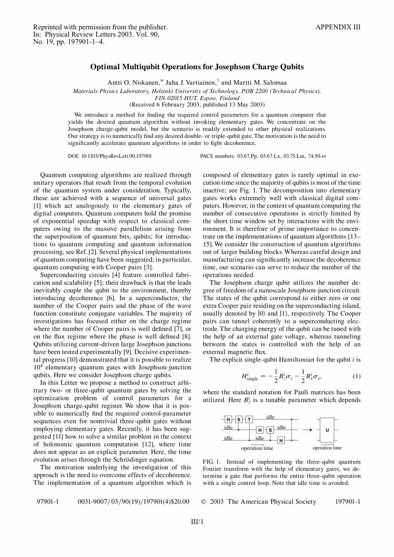
Optimal Multiqubit Operations for Josephson Charge Qubits
Antti O. Niskanen,* Juha J. Vartiainen,† and Martti M. SalomaaMaterials Physics Laboratory, Helsinki University of Technology, POB 2200 (Technical Physics),
FIN-02015 HUT, Espoo, Finland(Received 6 February 2003; published 13 May 2003)
We introduce a method for finding the required control parameters for a quantum computer thatyields the desired quantum algorithm without invoking elementary gates. We concentrate on theJosephson charge-qubit model, but the scenario is readily extended to other physical realizations.Our strategy is to numerically find any desired double- or triple-qubit gate. The motivation is the need tosignificantly accelerate quantum algorithms in order to fight decoherence.
DOI: 10.1103/PhysRevLett.90.197901 PACS numbers: 03.67.Pp, 03.67.Lx, 03.75.Lm, 74.50.+r
Quantum computing algorithms are realized throughunitary operators that result from the temporal evolutionof the quantum system under consideration. Typically,these are achieved with a sequence of universal gates[1] which act analogously to the elementary gates ofdigital computers. Quantum computers hold the promiseof exponential speedup with respect to classical com-puters owing to the massive parallelism arising fromthe superposition of quantum bits, qubits; for introduc-tions to quantum computing and quantum informationprocessing, see Ref. [2]. Several physical implementationsof quantum computing have been suggested; in particular,quantum computing with Cooper pairs [3].
Superconducting circuits [4] feature controlled fabri-cation and scalability [5]; their drawback is that the leadsinevitably couple the qubit to the environment, therebyintroducing decoherence [6]. In a superconductor, thenumber of the Cooper pairs and the phase of the wavefunction constitute conjugate variables. The majority ofinvestigations has focused either on the charge regimewhere the number of Cooper pairs is well defined [7], oron the flux regime where the phase is well defined [8].Qubits utilizing current-driven large Josephson junctionshave been tested experimentally [9]. Decisive experimen-tal progress [10] demonstrated that it is possible to realize104 elementary quantum gates with Josephson-junctionqubits. Here we consider Josephson charge qubits.
In this Letter we propose a method to construct arbi-trary two- or three-qubit quantum gates by solving theoptimization problem of control parameters for aJosephson charge-qubit register. We show that it is pos-sible to numerically find the required control-parametersequences even for nontrivial three-qubit gates withoutemploying elementary gates. Recently, it has been sug-gested [11] how to solve a similar problem in the contextof holonomic quantum computation [12], where timedoes not appear as an explicit parameter. Here, the timeevolution arises through the Schrodinger equation.
The motivation underlying the investigation of thisapproach is the need to overcome effects of decoherence.The implementation of a quantum algorithm which is
composed of elementary gates is rarely optimal in exe-cution time since the majority of qubits is most of the timeinactive; see Fig. 1. The decomposition into elementarygates works extremely well with classical digital com-puters. However, in the context of quantum computing thenumber of consecutive operations is strictly limited bythe short time window set by interactions with the envi-ronment. It is therefore of prime importance to concen-trate on the implementations of quantum algorithms [13–15]. We consider the construction of quantum algorithmsout of larger building blocks. Whereas careful design andmanufacturing can significantly increase the decoherencetime, our scenario can serve to reduce the number of theoperations needed.
The Josephson charge qubit utilizes the number de-gree of freedom of a nanoscale Josephson-junction circuit.The states of the qubit correspond to either zero or oneextra Cooper pair residing on the superconducting island,usually denoted by j0i and j1i, respectively. The Cooperpairs can tunnel coherently to a superconducting elec-trode. The charging energy of the qubit can be tuned withthe help of an external gate voltage, whereas tunnelingbetween the states is controlled with the help of anexternal magnetic flux.
The explicit single-qubit Hamiltonian for the qubit i is
Hisingle � � 1
2Biz�z � 1
2Bix�x; (1)
where the standard notation for Pauli matrices has beenutilized. Here Bi
z is a tunable parameter which depends
H S T
H S
H
idle
idle
idle
U
operation time operation time
idle
idle
FIG. 1. Instead of implementing the three-qubit quantumFourier transform with the help of elementary gates, we de-termine a gate that performs the entire three-qubit operationwith a single control loop. Note that idle time is avoided.
P H Y S I C A L R E V I E W L E T T E R S week ending16 MAY 2003VOLUME 90, NUMBER 19
197901-1 0031-9007=03=90(19)=197901(4)$20.00 © 2003 The American Physical Society 197901-1
III/1
Reprinted with permission from the publisher. APPENDIX IIIIn: Physical Review Letters 2003. Vol. 90,No. 19, pp. 197901-1–4.

on the gate voltage, while Bix can be controlled with
the help of a flux through the SQUID. Note that settingBiz � Bi
x � 0 results in degeneracy. At the degeneracypoint, there will be no change in the physical state ofthe system. In the case of single-qubit gates, it is easy tosee from this model that any rotation in SU(2) can beperformed on the qubits. Note that U(2) is not availablesince the Hamiltonian is traceless. In general, we cannotachieve U�2N� for N qubits since the Hamiltonian of theentire quantum register turns out to be traceless.However, the global phase factor is not physical since itcorresponds to a redefinition of the zero level of energy.
Qubits can be coupled by connecting them in parallelto an inductor; see Fig. 2. This scenario has the benefit ofallowing for a longer decoherence time and that of beingtunable. The resulting coupling term in the Hamiltonianbetween the qubits i and j is then of the form [4]
Hcoupling � �CBixB
jx�y � �y; (2)
where C is a positive parameter depending on the capaci-tances of the qubits and also on the inductance. It followsfrom Eqs. (1) and (2) that one can apply nontrivial two-qubit operations by simultaneously turning on theSQUIDs of the two qubits, although the �x term will beturned on as well. All the other qubits must have theirSQUIDs turned off. On the other hand, one-qubit �xoperations require that all but one SQUID is turned on.By turning off a SQUID we mean applying a half fluxquantum through it. Note that in the present context it isactually impossible to perform independent operations onany two subsets of the quantum register due to the in-ductive coupling. Since one must also take into accountthe decoherence mechanism, it is not practical to let mostqubits reside at their degeneracy point. The questionarises whether it would rather prove more efficient totry and find some scheme of finding larger quantumoperations, instead of using elementary gates.
To tackle the challenge posed above, we concentrate onfinding quantum gates numerically. The structure of theJosephson-qubit Hamiltonian is such that it is not imme-diately transparent how one would actually constructeven the basic controlled-NOT gate. We accomplish thisby considering loops ��t� in the control-parameter spacespanned by fBj
x�t�g and fBjz�t�g. Therefore, the function
��t� is of the vector form
��t� � �B1z�t� � � �BN
z �t� B1x�t� � � �BN
x �t��T; (3)
where we have assumed a register of N qubits. The tem-poral evolution induces the unitary operator
U � T exp
�i
Z��t�
H���t��dt!; (4)
where T stands for the time-ordering operator and wechoose �h � 1. The integration is performed along thepath formed by ��t� where the loop starts at the origin,i.e., at the degeneracy point. We will restrict the path to aspecial class of loops, which form polygons in the pa-rameter space. Thus the parameters vary in time at apiecewise constant speed, and none of the parameters isturned on or off instantaneously. We further set the timespent in traversing each edge of the polygon equal tounity. This limitation could be relaxed, in which casethe length of each edge in time would be an additionalfree parameter. We also set C � 1 in Eq. (2). This can beachieved by properly fabricating the inductor, but we haveevery reason to believe that the algorithm will work forother choices of C as well. Hence, in order to evaluateEq. (4) one needs only to specify the coordinates of thevertices of the polygon, which we denote collectively asX�. Numerically, it is easy to evaluate the unitary opera-tor in a stable manner by further dividing the loop ��t�into tiny intervals that take the time �t to traverse. If �idenotes all the values of the parameters in the midpoint ofthe ith interval, and m is the number of such intervals,then we find to a good approximation
UX� exp�� iH��m��t� � � � exp�� iH��1��t�: (5)
We now proceed to transform the problem of finding thedesired unitary operator into an optimization task.Namely, any UU can be found as the solution of the problemof minimizing the error functional
f�X�� � kUU�UX�kF (6)
over all possible values of X�. Here k � kF is the Frobeniustrace norm defined as kAkF �
������������������Tr�AyA�
p. The number
of adjustable vertices of the polygon � is kept fixedfrom the beginning. One needs to have enough verticesto parametrize the unitary group SU�2N�. The dimensionof this group is 22N � 1 and there are 2N parameters foreach vertex. Thus, we must have 2N� 22N � 1. We use� � 12 for the three-qubit gates and � � 4 for the two-qubit gates. Within this formulation the method of findingthe desired gates is similar to the recently introducedmethod of finding holonomic quantum gates [11]. Thuswe again expect the minimization landscape to be roughand we apply the robust polytope algorithm [16] for theminimization.
We concentrate on finding two- and three-qubit gates,since one-qubit gates can be trivially constructed with the
Φ1
V1
EJ ,CJ
L
Cg
Φ2
V2
EJ ,CJ
Cg
Φ3
V3
EJ ,CJ
Cg
FIG. 2. Schematic illustration of three Josephson charge qu-bits with inductive coupling. The adjustable parameters includethe gate voltages Vi and the enclosed fluxes �i.
P H Y S I C A L R E V I E W L E T T E R S week ending16 MAY 2003VOLUME 90, NUMBER 19
197901-2 197901-2
III/2

help of Euler angles. A larger quantum gate could be per-formed by factoring it into two- and three-qubit opera-tions, and the implementation for these could be foundnumerically. It seems that quantum operations for four,five, or more qubits could be found with the same method,assuming that sufficient computing resources are avail-able. However, even in the case of three-qubit gates theoptimization task becomes challenging and we need touse parallel programming. In the parallel three-qubitprogram, since the function evaluations of f�X�� requirea major part of the computation, we distribute the work-load such that each processor calculates the contributionof a single edge of the polygon. In addition, one processorhandles the minimization routine.
Let us turn to the results. First, we attempt to constructa gate equivalent to the controlled-NOT, namely,
U � exp
�i�4
�26641 0 0 00 1 0 00 0 0 10 0 1 0
3775: (7)
The phase factor is needed in order for the gate to belongto SU(4). It is already hard to see from the form of theHamiltonian how this gate would be carried out in thepresent setting. Figure 3 illustrates an implementation ofthis gate that has been obtained by minimizing the errorfunction in Eq. (6); the error is negligible. This exampleclearly illustrates the potential of our method.
As a second example, we construct the two-qubitquantum Fourier transform (QFT). The QFT (see, e.g.,Ref. [2]) is given in the case of two qubits by
F2 � 1
2
26641 1 1 11 i �1 �i1 �1 1 �11 �i �1 i
3775: (8)
Furthermore, we need to multiply this by exp�i �8� in orderto find a gate that belongs to SU(4). Figure 4 shows theresulting loop that has been found with the help of thealgorithm. In general, the optimization task for two-qubitgates can be performed quite easily with the help ofpersonal computers. However, finding three-qubit gatesis already quite time consuming. It proves worth the extraeffort to do this, though.
The three-qubit quantum Fourier transform is [2]
F3 � 1���8
p
2666666666664
1 1 1 1 1 1 1 11 ! !2 !3 !4 !5 !6 !7
1 !2 !4 !6 1 !2 !4 !6
1 !3 !6 ! !4 !7 !2 !5
1 !4 1 !4 1 !4 1 !4
1 !5 !2 !7 !4 !1 !6 !3
1 !6 !4 !2 1 !6 !4 !2
1 !7 !6 !5 !4 !3 !2 !
3777777777775;
(9)
where ! � exp�i �4�. Since det�F3� � i we must set UU �exp��i �
16�F3 such that UU 2 SU�8�. As an evidence of thesuccess of the three-qubit algorithm, we have in Fig. 5plotted the implementation of the three-qubit Fouriertransform. We conclude from these three examples thatit is possible to find far more powerful optimal imple-mentations of multiqubit quantum gates with the help ofthe minimization scheme [17].
To further assess the strength of the technique, wecompare the number of steps that are required to carryout the three-qubit Fourier transform using only two-qubit gates with the number of steps required when usingthe full three-qubit implementation of Fig. 5. The two-qubit implementation [18] requires effectively four gates;
0 1 2 3 4 5
-2
0
2
4
t
Fie
ld s
tren
gth Bz
1
Bx1
0 1 2 3 4 5
-2
0
2
4
t
Fie
ld s
tren
gth Bz
2
Bx2
FIG. 3. Control-parameter sequences as functions of time thatyield the gate in Eq. (7) which is equivalent to the controlled-NOT. The relative error is on the order of 10�11 and 100discretization points per edge were used.
0 1 2 3 4 5-4
0
4
8
t
Fie
ld s
tren
gth Bz
1
Bx1
0 1 2 3 4 5-4
0
4
8
t
Fie
ld s
tren
gth Bz
2
Bx2
FIG. 4. Control-parameter sequences as functions of timethat yield the two-qubit Fourier transform in Eq. (8). Therelative error is on the order of 10�11 and 100 discretizationpoints per edge were used.
P H Y S I C A L R E V I E W L E T T E R S week ending16 MAY 2003VOLUME 90, NUMBER 19
197901-3 197901-3
III/3

see Fig. 1. Since these gates would have to be performedsequentially, we would need five polygon edges pertwo-qubit operation. This results in 20 edges for the wholeoperation. Using elementary gates would require far moreedges. Our optimized three-qubit Fourier transform,though, only requires 13 edges. Since each edge contrib-utes the same amount to the operation time, we concludethat our implementation is improved. What is more, notall multiqubit gates can be decomposed as convenientlyas the Fourier transform. For them the gain is higher.Thus, increasing the amount of classical computing re-sources should yield even better results.
In conclusion, we have described how to efficientlyconstruct two- and three-qubit quantum gates for theJosephson charge qubit using numerical optimization.An immediate strength of the present scenario is thatone avoids unnecessary idle time during the logicalquantum operations. Since the loops are traversed at apiecewise constant speed, and no fields are instan-taneously switched, this method of constructing quan-tum gates should be viable from the experimental pointof view as well. The effect of finite fall and rise timesof pulses on the quality of quantum gates has beenstudied recently [19]. Since we do not use pulses butinstead interpolate along linear paths in the parame-ter space, such errors can be avoided. It seems reason-able to construct large-scale quantum algorithms inmultiqubit blocks. This can be accomplished by opti-mizing the gate realization with the help of classicalcomputers.
The authors thank M. Nakahara for useful discussionsand CSC (Finland) for computing resources. This work issupported by the Helsinki University of Technology andAcademy of Finland.
Note added.—After submitting our manuscript, workon a parallel switching method was kindly brought to ourattention by Burkard et al. [20].
*Currently at VTT Information Technology,Microsensing, POB 1207, 02044 VTT, Finland.Electronic address: [email protected]
†Electronic address: [email protected][1] A. Barenco, C. H. Bennett, R. Cleve, D. P. DiVincenzo,
N. Margolus, P. Shor, T. Sleator, J. Smolin, and H. Wein-furter, Phys. Rev. A 52, 3457 (1995).
[2] J. Gruska, Quantum Computing (McGraw-Hill, NewYork, 1999); M. A. Nielsen and I. L. Chuang, QuantumComputation and Quantum Information (CambridgeUniversity Press, Cambridge, 2000); A. Galindo andM. A. Martin-Delgado, Rev. Mod. Phys. 74, 347 (2002).
[3] A. Shnirman, G. Schon, and Z. Hermon, Phys. Rev. Lett.79, 2371 (1997); D.V. Averin, Solid State Commun. 105,659 (1998).
[4] Yu. Makhlin, G. Schon, and A. Shnirman, Rev. Mod.Phys. 73, 357 (2001).
[5] J. Q. You, J. S. Tsai, and F. Nori, Phys. Rev. Lett. 89,197902 (2002).
[6] W. H. Zurek, Rev. Mod. Phys. (to be published).[7] Y. Nakamura, Yu. A. Pashkin, and J. S. Tsai, Nature
(London) 398, 786 (1999); Phys. Rev. Lett. 87, 246601(2001).
[8] T. P. Orlando, J. E. Mooij, L. Tian, C. H. van der Wal,L. Levitov, S. Lloyd, and J. J. Mazo, Phys. Rev. B 60,15 398 (1999).
[9] J. M. Martinis, S. Nam, J. Aumentado, and C. Urbina,Phys. Rev. Lett. 89, 117901 (2002); Y. Yu, S. Han, X. Chu,S. Chu, and Z. Wang, Science 296, 889 (2002).
[10] D. Vion, A. Aassime, A. Cottet, P. Joyez, H. Pothier,C. Urbina, D. Esteve, and M. H. Devoret, Science 296,886 (2002).
[11] A. O. Niskanen, M. Nakahara, and M. M. Salomaa,Quantum Information and Computation 2, 560 (2002);Phys. Rev. A 67, 012319 (2003).
[12] P. Zanardi and M. Rasetti, Phys. Lett. A 264, 94 (1999).[13] J. Siewert and R. Fazio, Phys. Rev. Lett. 87, 257905
(2001).[14] J. P. Palao and R. Kosloff, Phys. Rev. Lett. 89, 188301
(2002).[15] X. Wang, A. Sørensen, and K. Mølmer, Phys. Rev. Lett.
86, 3907 (2001).[16] J. C. Lagarias, J. A. Reeds, M. H. Wright, and P. E. Wright,
SIAM J. Optim. 9, 112 (1998).[17] We have carried out sensitivity analyses on the CNOT and
two-qubit QFT gate realizations; the error was found toscale linearly with the rms of the Gaussian noise added ateach vertex: error 6� hnoiseirms.
[18] We assume that one-qubit operations are embedded intotwo-qubit gates.
[19] S. Oh, Phys. Rev. B 65, 144526 (2002).[20] G. Burkard, D. Loss, D. P. DiVincenzo, and J. A. Smolin,
Phys. Rev. B 60, 11404 (1999).
0 5 10-2
0
2
4Bz
1
Bx1
0 5 10 -2
0
2
4
Fie
ld s
tren
gth
Bz2
Bx2
0 5 10 -2
0
2
4
t
Bz3
Bx3
t
t
FIG. 5. Control-parameter sequences as functions of timethat yield the three-qubit quantum Fourier transform (moduloa global phase). The relative error is on the order of 10�5 and100 discretization points were used.
P H Y S I C A L R E V I E W L E T T E R S week ending16 MAY 2003VOLUME 90, NUMBER 19
197901-4 197901-4
III/4

International Journal of Quantum InformationVol. 2, No. 1 (2004) 1–10c© World Scientific Publishing Company
ACCELERATION OF QUANTUM ALGORITHMS USINGTHREE-QUBIT GATES
JUHA J. VARTIAINEN∗
Materials Physics Laboratory, Helsinki University of TechnologyPOB 2200 (Technical Physics), FIN-02015 HUT, Finland
ANTTI O. NISKANEN
VTT Information Technology, Microsensing, POB 1207, 02044 VTT, Finland
MIKIO NAKAHARA
Department of Physics, Kinki University, Higashi-Osaka 577-8502, Japan
MARTTI M. SALOMAA
Materials Physics Laboratory, Helsinki University of TechnologyPOB 2200 (Technical Physics), FIN-02015 HUT, Finland
Received 27 October 2003Revised 6 January 2004
Quantum-circuit optimization is essential for any practical realization of quantum com-
putation, in order to beat decoherence. We present a scheme for implementing the finalstage in the compilation of quantum circuits, i.e. for finding the actual physical realiza-tions of the individual modules in the quantum-gate library. We find that numerical opti-mization can be efficiently utilized in order to generate the appropriate control-parametersequences which produce the desired three-qubit modules within the Josephson charge-qubit model. Our work suggests ways in which one can in fact considerably reduce thenumber of gates required to implement a given quantum circuit, hence diminishing idletime and significantly accelerating the execution of quantum algorithms.
Keywords: decoherence; Josephson charge qubit; multiqubit quantum gates; numericaloptimization.
1. Introduction
The most celebrated and potentially useful quantum algorithms, which includeShor’s factorization algorithm1 and Grover’s search,2 manifest the potential of aquantum computer compared to its classical counterparts.
Widely different physical systems have been proposed to be utilized as a quan-tum computer.3,4 The main drawback shared by most of the physical realizations is
∗Corresponding author.
1
IV/1
Reprinted with permission from the publisher. APPENDIX IVIn: International Journal of Quantum Information 2004. Vol. 2, No. 1, pp. 1–10.

2 J. J. Vartiainen et al.
the short decoherence time. Decoherence5 destroys the pure quantum state which isneeded for the computation and, therefore, strongly limits the available executiontime for quantum algorithms. This, combined with the current restricted technicalpossibilities to construct and control nanoscale structures, delays the utilization ofquantum computation for reasonably extensive6 algorithms.
The execution time of a quantum algorithm can be reduced by optimization.The methods similar to those common in classical computation7 can be utilized inquantum compiling, constructing a quantum circuit8 for the algorithm. Moreover,the physical implementation of each gate can and must be optimized in order toachieve gate sequences long enough, for example, to implement Shor’s algorithmwithin typical decoherence times.9
Any quantum gate can be implemented by finding an elementary gatesequence10,11 which, in principle, exactly mimics the gate operation. In the mostgeneral case on the order of 4n elementary gates are needed to implement an arbi-trary n-qubit.12 Fortunately, remarkably shorter polynomial gate sequences areknown to implement many commonly used gates, such as the n-qubit quantumFourier transform (QFT). In addition to the exact methods, quantum gates can beimplemented using techniques which are approximative by nature.9,13–15
In this paper we consider the physical implementation of nontrivial three-gateoperations. As an example of the power of the technique, we show how to findrealizations for the Fredkin, Toffoli, and QFT gates through numerical optimization.These gates have been suggested to be utilized as basic building blocks for quantumcircuits and would thus act as basic extensions of the standard universal set ofelementary gates. However, the method presented can be employed to find therealization of any three-qubit gate. Having more computer resources available wouldallow one to construct gates acting on more than three qubits.
The numerical method allows us a straightforward and efficient way for findingthe physical implementation of any quantum gate. Thus, the method may prove tobe practical or even necessary for an efficient experimental realization of a quantumcomputer.
We concentrate on a hypothetical Josephson charge qubit register,16 since theexperimental investigations of superconducting qubits is active; see, for instance,Refs. 17–19. The scheme utilizes the number degree of freedom of the Cooper pairs ina superconducting Josephson-junction circuit. It is potentially scalable and it offers,in principle, full control over the quantum register. Moreover, the method employedhere is easily extended to any physical realization providing time-dependent controlover the physical parameters.
2. Physical Model
The physical implementation of a practical quantum algorithm requires that it isdecomposed into modules whose physical realizations are explicitly known. In thequantum computer, the gate operations are realized through unitary operations
IV/2

Acceleration of Quantum Algorithms Using Three-Qubit Gates 3
U that result from the temporal evolution of the physical state of the quantumregister. The unitary evolution is governed by the Hamiltonian matrix H(γ), whichdescribes the energy of the system for a given setting of physical parameters γ. Ingeneral, the parameters are time-dependent, γ = γ(t). The induced unitary operatoris obtained from the formal solution of the Schrodinger equation
U = T exp
(−i
∫γ(t)
H(γ(t))dt
), (1)
where T stands for the time-ordering operator and we have chosen � = 1.We consider the Josephson charge qubit register as a realization of a quantum
computer, see Fig. 1. The register is a homogenous array of mesoscopic supercon-ducting islands and the states of the qubit correspond to either zero or one extraCooper pair residing on the island. Each of the islands is capacitively coupled toan adjustable gate voltage, V i
g (t). In addition, they are coupled to a superconduct-ing lead through mesoscopic SQUIDs. We consider an ideal situation, where eachJosephson junction in the SQUID devices has the same Josephson energy EJ andcapacitance CJ. The magnetic flux Φi(t) through the ith SQUID loop is a con-trol parameter which may be produced by adjustable current Ii. The qubit arrayis coupled in parallel with an inductor, L, which allows the interaction betweenthe qubits.
In this scheme the Hamiltonian for the qubit register is9,16
H =n∑i
{−1
2Bi
zσiz − 1
2Bi
xσix
}−
n,n∑i�=j
CBixBj
xσiy ⊗ σj
y, (2)
where the standard notation for Pauli matrices has been utilized and σix stands
for I ⊗ · · · ⊗ σx ⊗ I · · · ⊗ I. Above, Bix can be controlled with the help of a flux
Φi(t) through the ith SQUID, Biz is a tunable parameter which depends on the gate
voltage Vg(t) and C is a constant parameter describing the strength of the coupling.We set C equal to unity by rescaling the Hamiltonian and time. The approach takenis to deal with the parameters Bi
z and Bix as dimensionless control parameters.
Fig. 1. Schematic of an array of Josephson charge qubits coupled in parallel with an inductor.
IV/3
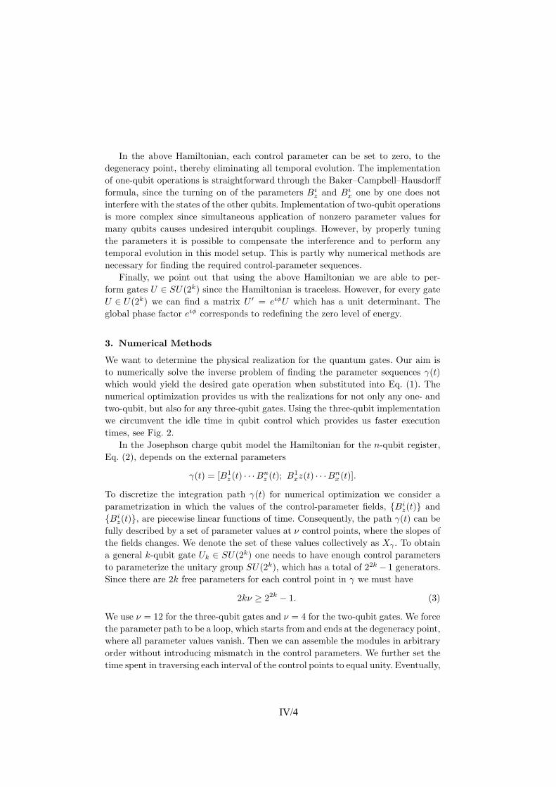
4 J. J. Vartiainen et al.
In the above Hamiltonian, each control parameter can be set to zero, to thedegeneracy point, thereby eliminating all temporal evolution. The implementationof one-qubit operations is straightforward through the Baker–Campbell–Hausdorffformula, since the turning on of the parameters Bi
z and Bix one by one does not
interfere with the states of the other qubits. Implementation of two-qubit operationsis more complex since simultaneous application of nonzero parameter values formany qubits causes undesired interqubit couplings. However, by properly tuningthe parameters it is possible to compensate the interference and to perform anytemporal evolution in this model setup. This is partly why numerical methods arenecessary for finding the required control-parameter sequences.
Finally, we point out that using the above Hamiltonian we are able to per-form gates U ∈ SU(2k) since the Hamiltonian is traceless. However, for every gateU ∈ U(2k) we can find a matrix U ′ = eiφU which has a unit determinant. Theglobal phase factor eiφ corresponds to redefining the zero level of energy.
3. Numerical Methods
We want to determine the physical realization for the quantum gates. Our aim isto numerically solve the inverse problem of finding the parameter sequences γ(t)which would yield the desired gate operation when substituted into Eq. (1). Thenumerical optimization provides us with the realizations for not only any one- andtwo-qubit, but also for any three-qubit gates. Using the three-qubit implementationwe circumvent the idle time in qubit control which provides us faster executiontimes, see Fig. 2.
In the Josephson charge qubit model the Hamiltonian for the n-qubit register,Eq. (2), depends on the external parameters
γ(t) = [B1z (t) · · · Bn
z (t); B1xz(t) · · · Bn
x (t)].
To discretize the integration path γ(t) for numerical optimization we consider aparametrization in which the values of the control-parameter fields, {Bi
z(t)} and{Bi
z(t)}, are piecewise linear functions of time. Consequently, the path γ(t) can befully described by a set of parameter values at ν control points, where the slopes ofthe fields changes. We denote the set of these values collectively as Xγ . To obtaina general k-qubit gate Uk ∈ SU(2k) one needs to have enough control parametersto parameterize the unitary group SU(2k), which has a total of 22k − 1 generators.Since there are 2k free parameters for each control point in γ we must have
2kν ≥ 22k − 1. (3)
We use ν = 12 for the three-qubit gates and ν = 4 for the two-qubit gates. We forcethe parameter path to be a loop, which starts from and ends at the degeneracy point,where all parameter values vanish. Then we can assemble the modules in arbitraryorder without introducing mismatch in the control parameters. We further set thetime spent in traversing each interval of the control points to equal unity. Eventually,
IV/4

Acceleration of Quantum Algorithms Using Three-Qubit Gates 5
Fig. 2. Implementation of the Fredkin gate on the Josephson charge qubit model. (a) The quan-tum circuit symbol of the Fredkin gate, and (b) its physical implementation by controlling all threequbits simultaneously. (c) The two-qubit gate decomposition of the Fredkin gate. Here V =
√σx
and V ∗ stands for its Hermitian conjugate. (d) The physical implementation of the gate sequence;note that during each gate operation, one of the qubits is in the idle state. The vertical axis infigures (b) and (d) stands for the control parameter field amplitudes; the solid line describes theparameter Bi
z and the dotted line the parameter Bix, see text.
the execution time of Uk is proportional to ν + 1, which gives us a measure tocompare different implementations. Figure 2 illustrates our approach and showsthe benefits of the three-qubit implementation of the Fredkin gate compared tocorresponding implementation through two-qubit gate decomposition. Note thatthe two-qubit gate implementation could be further optimized.20
We evaluate the unitary operator in Eq. (1) in a numerically robust manner bydividing the loop γ(t) into tiny intervals that take time ∆t to traverse. If γi denotesall the values of the parameters in the midpoint of the ith interval, and m is thenumber of such intervals, we then find to a good approximation
UXγ ≈ exp(−iH(γm)∆t) · · · exp(−iH(γ1)∆t). (4)
The evaluation of the UXγ consists of independent matrix multiplications whichcan be evaluated simultaneously. This allows straightforward parallelization of thecomputation. To calculate the matrix exponentials efficiently we use the truncatedTaylor-series expansion
eA ≈m∑
k=0
Ak
k!, (5)
IV/5
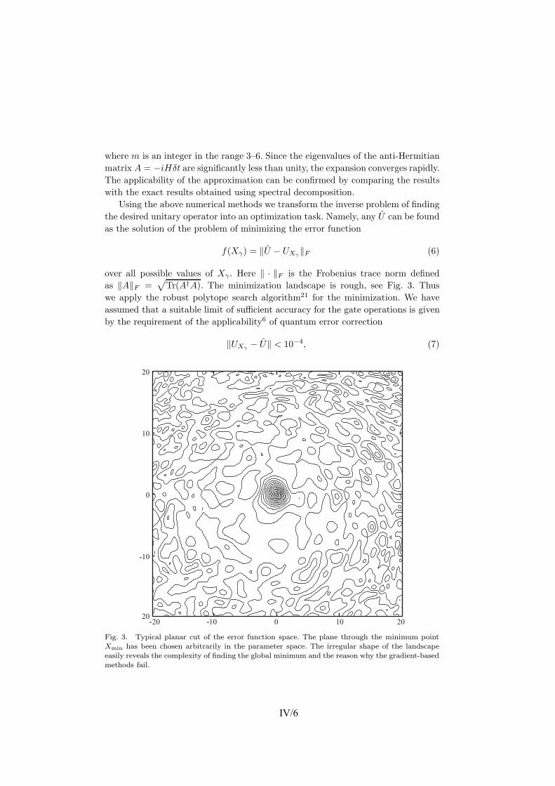
6 J. J. Vartiainen et al.
where m is an integer in the range 3–6. Since the eigenvalues of the anti-Hermitianmatrix A = −iHδt are significantly less than unity, the expansion converges rapidly.The applicability of the approximation can be confirmed by comparing the resultswith the exact results obtained using spectral decomposition.
Using the above numerical methods we transform the inverse problem of findingthe desired unitary operator into an optimization task. Namely, any U can be foundas the solution of the problem of minimizing the error function
f(Xγ) = ‖U − UXγ ‖F (6)
over all possible values of Xγ . Here ‖ · ‖F is the Frobenius trace norm definedas ‖A‖F =
√Tr(A†A). The minimization landscape is rough, see Fig. 3. Thus
we apply the robust polytope search algorithm21 for the minimization. We haveassumed that a suitable limit of sufficient accuracy for the gate operations is givenby the requirement of the applicability6 of quantum error correction
‖UXγ − U‖ < 10−4, (7)
Fig. 3. Typical planar cut of the error function space. The plane through the minimum pointXmin has been chosen arbitrarily in the parameter space. The irregular shape of the landscapeeasily reveals the complexity of finding the global minimum and the reason why the gradient-basedmethods fail.
IV/6

Acceleration of Quantum Algorithms Using Three-Qubit Gates 7
where U and UXγ are the target and the numerically optimized gate operations,respectively.
4. Quantum Gate Optimization Results
We have applied the minimization procedure to various three-qubit gates and foundthat the error functional of Eq. (6) can be minimized to values below 10−4 byrunning the polytope search repetitively. Table 1 represents the optimized controlparameters which serve to yield the Fredkin gate when applied to the Josephsoncharge qubit Hamiltonian. Numerical results for the Toffoli and three-qubit QFTgates are represented in Tables 2 and 3, respectively. Finding the control parameterusing the polytope search requires an order of 106 error-function evaluations, which
Table 1. Field amplitudes at the control points for the Fredkin gate.
Time B1z B2
z B3z B1
x B2x B3
x
1 0.00000 0.00000 0.00000 0.00000 0.00000 0.000002 0.71637 −1.44846 1.54511 0.55428 0.67228 −0.581053 2.23337 0.18377 1.73522 1.29275 −0.69463 0.015134 1.17895 −1.31725 −2.22145 −1.11461 0.27210 −0.186655 −0.92555 1.97326 −1.15875 1.49438 2.69507 1.578726 −0.54804 0.66834 0.48872 −0.38981 −1.88659 −0.602267 1.18034 −2.13101 −0.81205 −0.27817 2.13894 0.922088 −0.59994 2.80989 0.82839 −0.24260 −1.09419 2.095619 2.78429 0.35914 1.98896 −0.11839 0.90439 0.83671
10 0.79364 2.40575 −1.78131 0.67600 3.31481 0.1782811 −0.41098 −0.69585 0.15594 −0.21996 0.70917 0.1537712 0.12630 3.39809 2.14043 1.65229 0.37794 −0.6422313 0.84941 −1.17701 1.28801 −1.84075 1.16739 0.3396514 0.00000 0.00000 0.00000 0.00000 0.00000 0.00000
Table 2. Field amplitudes at the control points for the Toffoli gate.
Time B1z B2
z B3z B1
x B2x B3
x
1 0.00000 0.00000 0.00000 0.00000 0.00000 0.000002 0.00286 −0.06484 0.96050 0.72386 0.33310 −0.220263 2.85647 −0.08874 2.94358 1.60795 −0.18192 0.039314 0.67879 −1.70364 −2.54280 −1.65771 −0.04722 −0.254115 −0.17379 0.87916 0.19581 1.55484 2.98447 1.22991
6 0.01847 2.68973 −0.18098 0.02898 −0.54301 −0.159777 0.21569 −3.27483 −0.33407 −0.31173 2.26503 0.320318 −0.57439 4.25644 1.25986 0.12262 0.06238 1.876199 3.40836 −0.48759 0.44296 −0.20867 0.04664 1.00381
10 −0.60520 1.59369 0.87620 0.95412 2.75968 0.3720911 −0.10762 0.16258 −0.24672 −0.11839 1.38245 0.0199012 0.20275 1.97553 1.12769 1.07003 0.46081 −0.3543713 0.99088 −0.23145 0.68050 −2.12999 0.74237 0.0153714 0.00000 0.00000 0.00000 0.00000 0.00000 0.00000
IV/7

8 J. J. Vartiainen et al.
Table 3. Field amplitudes for the three-qubit QFT gate.
Time B1z B2
z B3z B1
x B2x B3
x
1 0.00000 0.00000 0.00000 0.00000 0.00000 0.00000
2 0.49824 0.41039 1.75837 0.42339 0.67345 1.832573 −0.18007 0.55372 −1.79297 0.64987 0.53048 −0.393004 0.73625 0.60488 −0.94171 0.61458 0.09641 −0.398635 2.21744 1.28419 2.82723 0.47046 1.04206 1.593456 0.47037 −0.48092 −0.53215 0.04297 0.21802 1.240637 0.69085 0.72558 1.00427 0.22332 1.25082 −0.251448 2.61154 0.87134 0.74335 0.31834 −0.00374 1.646439 0.24827 0.82952 1.04102 2.31043 1.00804 0.98377
10 −0.90785 −1.32491 1.10923 0.69935 −0.15359 −0.3442011 0.59315 1.36082 −0.19764 1.83023 0.58541 0.8545312 0.76819 0.31529 0.24531 −0.40221 1.13052 0.6818413 −0.85651 0.02093 0.85491 1.33447 0.56580 0.0633214 0.00000 0.00000 0.00000 0.00000 0.00000 0.00000
Table 4. Comparison of the execution times for various quantum gates.
Gate Fredkin Toffoli QFT U ∈ SU(23) U ∈ SU(23)Decomposed 3-qubit Gates
Number of two-qubit gates 5 3 3 206 —Execution time 25 15 15 1030 13
takes tens of hours of CPU time, but can be done in a reasonable time by usingparallel computing.
We found that the error functional grows linearly in the vicinity of the minimumpoint Xγ , which implies that the parameter sequence found may be robust. Therobustness was further analyzed by adding Gaussian noise to the control parametersof the path γ(t). Such a sensitivity analysis confirmed that the error scales linearlywith the root-mean-square amplitude of the surplus Gaussian noise.
In our scheme, any three-qubit gate requires an integration path γ(t) with 12control points, which takes 13 units of time to execute. Similarly, a two-qubit gatetakes 5 units of time to execute. Table 4 summarizes our results by comparingthe number of steps that are required to carry out a single three-qubit gate orusing a sequence of two-qubit gates. The results are calculated for the Fredkin andToffoli gates following the decomposition given in Refs. 20 and 10. For a QFT gatethe quantum circuit is explicitly shown, for example, in Ref. 22. Any three-qubitgate can be realized by using 68 controlled2 U and controlled2 NOT gates. Thisnumber can be reduced to 50 using palindromic optimization.23 The decompositionof the controlled2 U gate is discussed in Ref. 10. Note that the results in Table 4are calculated assuming that the physical realization for any two qubit modules isavailable through some scheme similar to the one which is employed in this paperand one-qubit gates are merged into two-qubit modules. The implementation of
IV/8

Acceleration of Quantum Algorithms Using Three-Qubit Gates 9
a general three-qubit module using a limited set of gates, for example, one-qubitrotations Ry and Rz and the CNOT gate has recently been discussed in Ref. 12.
5. Discussion
We have shown how to obtain approximative control-parameter sequences for aJosephson charge-qubit register with the help of a numerical optimization scheme.The scheme utilizes well known theoretical methods and the results are obtainedthrough heavy computation. Our method can prove useful for experimental real-ization of working quantum computers. The possibility to implement nontrivialmultiqubit gates in an efficient way may well turn out to be a crucial improvementin making quantum computing realizable. For example, Josephson-junction qubitssuffer from a short decoherence time, in spite of their potential scalability, andtherefore the runtime of the algorithm must be minimized using all the possibleingenuity imaginable.
Here we have utilized piecewise linear parameter paths. This makes the schemeexperimentally more viable than the pulse-gate solutions, since the parameters areadjusted such that no fields are switched instantaneously. However, the numeri-cal method proposed for solving the time evolution operator is not unique. Someimplicit methods for the integration in time may turn out to yield the results moreaccurately in the same computational time. Furthermore, for practical applicationsit may turn out to be useful to try and describe the parameter paths using a collec-tion of smooth functions and to find whether they would produce the required gates.
To summarize the results of our numerical optimization, we emphasize that moreefficient implementations for quantum algorithms can be found using numericallyoptimized three-qubit gates. In the construction of large-scale quantum algorithmseven larger multiqubit modules may prove powerful. The general idea is to useclassical computation to minimize quantum computation time, aiming below thedecoherence limit.
Acknowledgements
JJV thanks the Foundation of Technology (TES, Finland) for a scholarship and theEmil Aaltonen Foundation for a travel grant to attend EQIS’03 in Japan; MN isgrateful for partial support of a Grant-in-Aid from the Ministry of Education, Cul-ture, Sports, Science, and Technology, Japan (Project Nos. 14540346 and 13135215).This research has been supported in the Materials Physics Laboratory at HUT bythe Academy of Finland through the Research Grants in Theoretical MaterialsPhysics (No. 201710) and in Quantum Computation (No. 206457). We also want tothank CSC — Scientific Computing Ltd. (Finland) for parallel computing resources.
References
1. P. W. Shor, Algorithms for quantum computation: Discrete logarithms andfactoring in Proc. 35nd Annual Symposium on Foundations of Computer Science,ed. S. Goldwasser (IEEE Computer Society Press, 1994), p. 124.
IV/9

10 J. J. Vartiainen et al.
2. L. K. Grover, Phys. Rev. Lett. 79, 325 (1997).3. R. Clark (ed.), Experimental Implementation of Quantum Computation (IQC ’01)
(Rinton Press Inc., New Jersey, 2001).4. F. De Martini (ed.), Experimental Quantum Computation and Information (Inter-
national School of Physics “Enrico Fermi”, Vol. 148) (IOS Press, Amsterdam, 2002).5. W. H. Zurek, Rev. Mod. Phys. 75, 715 (2003).6. D. P. DiVincenzo, Fortschr. Phys. 48, 771 (2000).7. A. V. Aho, R. Sethi and J. D. Ullman, Compilers: Principles, Techniques and Tools
(Addison-Wesley, Reading, Massachusetts, 1986).8. D. Deutsch, Proc. Roy. Soc. London A425, 73 (1989).9. A. O. Niskanen, J. J. Vartiainen and M. M. Salomaa, Phys. Rev. Lett. 90, 197901
(2003); J. J. Vartiainen, A. O. Niskanen, M. Nakahara and M. M. Salomaa, Imple-menting Shor’s algorithm on Josephson charge qubits, quant-ph/0308171.
10. A. Barenco, C. H. Bennett, R. Cleve, D. P. DiVincenzo, N. Margolus, P. Shor,T. Sleator, J. Smolin and H. Weinfurter, Phys. Rev. A52, 3457 (1995).
11. J. Zhang, J. Vala, S. Sastry and B. Whaley, Phys. Rev. Lett. 91, 027903 (2003).12. V. V. Shende, I. L. Markov and S. S. Bullock, On universal gate libraries and generic
minimal two-qubit quantum circuits, quant-ph/0308033.13. A. W. Harrow, B. Recht and I. L. Chuang, J. Math. Phys. 43, 4445 (2002).14. E. Knill, Approximation by quantum circuits, quant-ph/9508006.15. G. Burkard, D. Loss, D. P. DiVincenzo and J. A. Smolin, Phys. Rev. B60, 11404
(1999).16. Y. Makhlin, G. Schon and A. Shnirman, Rev. Mod. Phys. 73, 357 (2001).17. Y. A. Pashkin, T. Yamamoto, O. Astafiev, Y. Nakamura, D. V. Averin and J. S. Tsai,
Nature 421, 823 (2003).18. T. Yamamoto, Y. A. Pashkin, O. Astafiev, Y. Nakamura, D. V. Averin and J. S. Tsai,
Nature 425, 944 (2003).19. J. M. Martinis, S. Nam, J. Aumentado and C. Urbina, Phys. Rev. Lett. 89, 117901
(2002).20. J. A. Smolin and D. P. DiVincenzo, Phys. Rev. A53, 2855 (1996).21. J. C. Lagarias, J. A. Reeds, M. H. Wright and P. E. Wright, SIAM J. Optim. 9, 112
(1998).22. J. Gruska, Quantum Computing (McGraw-Hill, New York, NY, 1999), p. 118.23. A. V. Aho and K. M. Svore, Compiling quantum circuits using the Palindrome
transform, quant-ph/0311008.
IV/10

Implementing Shor’s algorithm on Josephson charge qubits
Juha J. Vartiainen,1,* Antti O. Niskanen,2 Mikio Nakahara,1,3 and Martti M. Salomaa11Materials Physics Laboratory, POB 2200 (Technical Physics), Helsinki University of Technology, FIN-02015 HUT, Finland
2VTT Information Technology, Microsensing, POB 1207, 02044 VTT, Finland3Department of Physics, Kinki University, Higashi-Osaka 577-8502, Japan
(Received 6 October 2003; revised manuscript received 27 February 2004; published 30 July 2004)
We investigate the physical implementation of Shor’s factorization algorithm on a Josephson charge qubitregister. While we pursue a universal method to factor a composite integer of any size, the scheme is demon-strated for the number 21. We consider both the physical and algorithmic requirements for an optimal imple-mentation when only a small number of qubits are available. These aspects of quantum computation are usuallythe topics of separate research communities; we present a unifying discussion of both of these fundamentalfeatures bridging Shor’s algorithm to its physical realization using Josephson junction qubits. In order to meetthe stringent requirements set by a short decoherence time, we accelerate the algorithm by decomposing thequantum circuit into tailored two- and three-qubit gates and we find their physical realizations through nu-merical optimization.
DOI: 10.1103/PhysRevA.70.012319 PACS number(s): 03.67.Lx, 03.75.Lm
I. INTRODUCTION
Quantum computers have potentially superior computingpower over their classical counterparts[1,2]. The novel com-puting principles which are based on the quantum-mechanical superposition of states and their entanglementmanifest themselves, for example, in Shor’s integer-factorization algorithm[3] and in Grover’s database search[4]. In this paper we focus on Shor’s algorithm which isimportant owing to its potential applications in(de)cryptog-raphy. Many widely applied methods of public-key cryptog-raphy are currently based on the RSA algorithm[5] whichrelies on the computational difficulty of factoring large inte-gers.
Recently, remarkable progress toward the experimentalrealization of a quantum computer has been accomplished,for instance, using nuclear spins[6,7], trapped ions[8,9],cavity quantum electrodynamics[10], electrons in quantumdots [11], and superconducting circuits[12–17]. However,the construction of a large multiqubit register remains ex-tremely challenging. The very many degrees of freedom ofthe environment tend to become entangled with those of thequbit register which results in undesirable decoherence[18].This imposes a limit on the coherent execution time availablefor the quantum computation. The shortness of the decoher-ence time may present fundamental difficulties in scaling thequantum register up to large sizes, which is the basic require-ment for the realization of nontrivial quantum algorithms[19].
In this paper, we consider an inductively coupled charge-qubit model[20]. Josephson-junction circuits provide two-state pseudospin systems whose different spin componentscorrespond to distinct macroscopic variables: either thecharges on the superconducting islands or the phase differ-ences over the Josephson junctions. Thus, depending on the
parameter values for the setup, one has flux[12,13], orcharge qubits[14–17,21]. Thus far the largest quantum reg-ister, comprising seven qubits, has been demonstrated fornuclear magnetic resonance(NMR) in a liquid solution[7].However, the NMR technique is not believed to be scalableto much larger registers. In contrast, superconductingJosephson-junction circuits are supposed to provide scalableregisters and hence to be better applicable for large quantumalgorithms[22]. Furthermore, they allow integration of thecontrol and measurement electronics. On the other hand, thecoupling to the environment, e.g., through the electricalleads,[23] causes short decoherence times.
In addition to the quantum register, one needs a quantumgate “library,” i.e., a collection of control parameter se-quences which implements the gate operations on the quan-tum register. The quantum gate library must consist of atleast a set of universal elementary gates[24], which are typi-cally chosen to be the one-qubit unitary rotations and theCNOT gate. Some complicated gates may also be included inthe library.
The quantum circuit made of these gates resembles theoperational principle of a conventional digital computer. Tominimize the number of gates, the structure of the quantumcircuit can be optimized using methods similar to those indigital computing[25]. Minimizing the number of gates isimportant not only for fighting decoherence but also for de-creasing accumulative errors of classical origin. If some tai-lored two-, three- or arbitraryk-qubit gates are included inthe gate library, the quantum circuits may be made muchmore compact. The implementation of gates acting on morethan two qubits calls for numerical optimization[26]. Forfurther discussion on the implementation of non-standardgates as the building blocks for quantum circuits, see Refs.[27–30].
We propose an implementation of Shor’s algorithm forfactoring moderately large integers—we deal with both algo-rithmic and hardware issues in this paper. These are two keyaspects of quantum computation which, however, have tradi-tionally been topics of disjoint research communities. Hence*Electronic address: [email protected]
PHYSICAL REVIEW A 70, 012319(2004)
1050-2947/2004/70(1)/012319(11)/$22.50 ©2004 The American Physical Society70 012319-1
V/1
Reprinted with permission from the publisher. APPENDIX VIn: Physical Review 2004. Vol. A 70, pp. 012319-1–11.
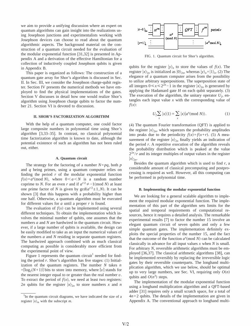
we aim to provide a unifying discussion where an expert onquantum algorithms can gain insight into the realizations us-ing Josephson junctions and experimentalists working withJosephson devices can choose to read about the quantumalgorithmic aspects. The background material on the con-struction of a quantum circuit needed for the evaluation ofthe modular exponential function[31,32] is presented in Ap-pendix A and a derivation of the effective Hamiltonian for acollection of inductively coupled Josephson qubits is givenin Appendix B.
This paper is organized as follows: The construction of aquantum gate array for Shor’s algorithm is discussed in Sec.II. In Sec. III, we consider the Josephson charge-qubit regis-ter. Section IV presents the numerical methods we have em-ployed to find the physical implementations of the gates.Section V discusses in detail how one would realize Shor’salgorithm using Josephson charge qubits to factor the num-ber 21. Section VI is devoted to discussion.
II. SHOR’S FACTORIZATION ALGORITHM
With the help of a quantum computer, one could factorlarge composite numbers in polynomial time using Shor’salgorithm [3,33–35]. In contrast, no classical polynomialtime factorization algorithm is known to date, although thepotential existence of such an algorithm has not been ruledout, either.
A. Quantum circuit
The strategy for the factoring of a numberN=pq, both pand q being primes, using a quantum computer relies onfinding the periodr of the modular exponential functionfsxd=axsmod Nd, where 0,a,N is a random numbercoprime toN. For an evenr and if ar/2Þ−1smod Nd at leastone prime factor ofN is given by gcdsar/2±1,Nd. It can beshown [3] that this happens with a probability higher thanone half. Otherwise, a quantum algorithm must be executedfor different values fora until a properr is found.
The evaluation offsxd can be implemented using severaldifferent techniques. To obtain the implementation which in-volves the minimal number of qubits, one assumes that thenumbersa andN are hardwired in the quantum circuit. How-ever, if a large number of qubits is available, the design canbe easily modified to take as an input the numerical values ofthe numbersa andN residing in separate quantum registers.The hardwired approach combined with as much classicalcomputing as possible is considerably more efficient fromthe experimental point of view.
Figure 1 represents the quantum circuit1 needed for find-ing the periodr. Shor’s algorithm has five stages:(1) Initial-ization of the quantum registers. The numberN takes n= dlog2sN+1de bits to store into memory, wheredve stands forthe nearest integer equal to or greater than the real numberv.To extract the period offsxd, we need at least two registers:2n qubits for the registeruxl2n to store numbersx and n
qubits for the registeruyln to store the values offsxd. Theregisteruxl2n is initialized asu0l2n, whereasuyln= u1ln. (2) Theelegance of a quantum computer arises from the possibilityto utilize arbitrary superpositions. The superposition state ofall integers 0øxø22n−1 in the registeruxl2n is generated byapplying the Hadamard gateH on each qubit separately.(3)The execution of the algorithm, the unitary operatorUf, en-tangles each input valuex with the corresponding value offsxd:
Ufox
uxlu1l = ox
uxluaxsmod Ndl. s1d
(4) The quantum Fourier transformationsQFTd is applied tothe registeruxl2n, which squeezes the probability amplitudesinto peaks due to the periodicityfsxd= fsx+rd. (5) A mea-surement of the registeruxl2n finally yields an indication ofthe periodr. A repetitive execution of the algorithm revealsthe probability distribution which is peaked at the value22n/ r and its integer multiples of output values in the registeruxl2n.
Besides the quantum algorithm which is used to findr, aconsiderable amount of classical precomputing and postpro-cessing is required as well. However, all this computing canbe performed in polynomial time.
B. Implementing the modular exponential function
We are looking for a general scalable algorithm to imple-ment the required modular exponential function. The imple-mentation of this part of the algorithm sets limits for thespatial and temporal requirements of computational re-sources, hence it requires a detailed analysis. The remarkableexperimental results[7] to factor the number 15 involve anelegant quantum circuit of seven qubits and only a fewsimple quantum gates. The implementation definitely ex-ploits the special properties of the number 15, and the factthat the outcome of the functionaxsmod Nd can be calculatedclassically in advance for all input valuesx whenN is small.For arbitraryN, reversible arithmetic algorithms must be em-ployed[36,37]. The classical arithmetic algorithms[38], canbe implemented reversibly by replacing the irreversible logicgates by their reversible counterparts. The longhand multi-plication algorithm, which we use below, should be optimalup to very large numbers, see Sec. VI, requiring onlyOsndqubits andOsn3d steps.
The implementation of the modular exponential functionusing a longhand multiplication algorithm and a QFT-basedadder[31] requires only a small scratch space, for a total of4n+2 qubits. The details of the implementation are given inAppendix A. The conventional approach to longhand multi-
1In the quantum circuit diagrams, we have indicated the size of aregisteruxlm with the subscriptm.
FIG. 1. Quantum circuit for Shor’s algorithm.
VARTIAINEN et al. PHYSICAL REVIEW A 70, 012319(2004)
012319-2
V/2

plication without a QFT-based adder would require on theorder of 5n qubits. The price of the reduced space is theincrease in the execution time, which now isOsn4d, butwhich can be reduced down toO(n3 log2sn/ed), allowing fora certain error levele. According to Ref.[31] one wouldachieve an algorithm requiring only 2n+3 qubits with inter-mediate measurements. However, we do not utilize thisimplementation since the measurements are likely to intro-duce decoherence.
III. JOSEPHSON CHARGE-QUBIT REGISTER
The physical model studied in this paper is the so-calledinductively coupled Cooper pair box array. This model, aswell as other related realizations of quantum computing, hasbeen analyzed in Ref.[20]. The derivation of the Hamil-tonian is outlined in Appendix B for completeness. Our ap-proach to quantum gate construction is slightly differentfrom those found in the literature and it is therefore worth-while to consider the physical model in some detail.
A schematic picture of a homogeneous array of qubits isshown in Fig. 2. Each qubiti comprises a superconductingisland coupled capacitively to a gate voltage and a supercon-ducting quantum interference devicesSQUIDd loop throughwhich Cooper pairs may tunnel. The gate voltage may beused to tune the effective gate chargeng
i of the islandwhereas the external magnetic flux through the SQUID canbe used to control the effective Josephson energy. Each qubitis characterized by a charging energyEC and a tunable Jo-sephson energyEJsFid, whereFi is the flux threading theSQUID. The Hamiltonian for theith qubit can be written as
Hsinglei = − 1
2Bzi sz
i − 12Bx
i sxi s2d
and the coupling between theith and j th qubits as
Hcouplingi,j = − CBx
i Bxj sy
i^ sy
j . s3d
The qubit stateu0l (“spin up”) corresponds to zero extraCooper pairs residing on the island and the stateu1l (“spindown”) corresponds to one extra pair on the island. AboveBx
i =EJsFid, Bzi =ECs1−2ng
i d, and C=p2L /F02sCqb/CJ
2d de-notes the strength of the coupling between the qubits,whereasCqb is the total capacitance of a qubit in the circuit,CJ is the capacitance of the SQUID,L is the inductancewhich may in practice be caused by a large Josephson junc-tion operating in the linear regime and finallyF0=h/2e isthe flux quantum. The approach taken is to deal with theparametersBz
i and Bxi as dimensionless control parameters.
We assume that they can be set equal to zero which is inprinciple possible if the SQUID junctions are identical. WesetC=1 and choose natural units such that"=1.
The Hamiltonian in Eqs.(2) and(3) is a convenient modelfor studying the construction of quantum algorithms for anumber of reasons. First of all, the total Hamiltonian can beset to zero thereby eliminating all temporal evolution. Sec-ond, setting the effective Josephson coupling to zero elimi-nates the coupling between any two qubits. This is achievedby applying half a flux quantum through the SQUID loops. Ifthe Josephson energy of any two qubits is nonzero, there willautomatically emerge a coupling between them. This ispartly why numerical methods are necessary for finding thecontrol-parameter sequences. By properly tuning the gatevoltages and fluxes it is possible to compensate undesiredcouplings and to perform any temporal evolution in thismodel setup.
We note that the generatorsisx and isz are sufficient toconstruct all the SUs2d matrices through the Baker-Campbell-Hausdorff formula and thus single-qubit gatesneed not be constructed numerically. It is even possible to dothis in a piecewise linear manner avoiding abrupt switchingsince the only relevant parameter is the time integral of eitherBz
i or Bxi if only one of them is nonzero at a time. That is, any
UPSUs2d acting on theith qubit can be written as
U = expSisziE
t2
t3
Bzi stddt/2DexpSisx
iEt1
t2
Bxi stddt/2D
3expSisziE
t0
t1
Bzi stddt/2D , s4d
where we assume that fromt0 to t1 only Bzi is nonzero, from
t1 to t2 only Bxi is nonzero and fromt2 to t3 only Bz
i is againnonzero. For instance, the gateiH PSUs2d, equivalent to theHadamard gateHPUs2d up to a global phase, can be real-ized as in Fig. 3 by properly choosing the time-integrals inEq. (4). We cannot achieve Us2nd for n qubits since theHamiltonian for the entire quantum register turns out to betraceless, thus producing only SUs2nd matrices. However, theglobal phase factor is not physical.
The above Hamiltonian is an idealization and does nottake any decoherence mechanisms into account. To justify
FIG. 2. (a) Schematic of a Josephson charge qubit with therelevant parameters.(b) An array of Josephson charge qubitscoupled in parallel with an inductor.
IMPLEMENTING SHOR’S ALGORITHM ON JOSEPHSON… PHYSICAL REVIEW A 70, 012319(2004)
012319-3
V/3

this omission, we have to ensure that a charge-qubit registeris decoherence-free for time scales long enough to execute apractical quantum algorithm. In addition, we have neglectedthe inhomogenity of the SQUIDs. It may be extremely chal-lenging to fabricate sufficiently uniform junctions. A three-junction design might alleviate this problem. Whereas for thecontrol of M two-junction SQUIDs one needs at leastMindependent sources of flux, the three-junction design wouldcall for 2M independent sources. The extra sources may beused to compensate the structural nonuniformities. The noisein the control parameters has also been neglected but it willturn out that the error will grow linearly with the rms dis-placement of uncorrelated Gaussian noise. Correlated noisemay only be tolerated if it is very weak. We have also ne-glected the issue of quantum measurement altogether in theabove.
A crucial assumption is thatkBT ln Nqp!EJ!EC!DBCS,whereNqp is the number of quasiparticle modes. Typical op-eration frequencies would be in the GHz range and the op-eration temperature could be tens of mK. For our two-stateHamiltonian to apply, we should actually insist that, insteadof EJ!EC, the requirementEJsFid!EC holds. It may appearat first thatBx
i cannot take on values exceedingBzi . However,
this does not hold since the gate charge also plays a role;values ofBz
i can be very small ifngi is tuned close to one half.
Since we employ natural units we may freely rescale theHamiltonian while rescaling time. This justifies our choiceC=1 above. Furthermore, it is always possible to confine theparameter values within an experimentally accessible range.For more discussion, see Ref.[20].
IV. IMPLEMENTING A QUANTUM-GATE LIBRARY
The evaluation of the time-development operatorU isstraightforward once the externally controlled physical pa-rameters for the quantum register are given. Here we usenumerical optimization to solve the inverse problem; namely,we find the proper sequence for the control variables whichproduce the given quantum gate.
A. Unitary time evolution
The temporal evolution of the Josephson charge-qubitregister is described by a unitary operator
Ugstd = T expS− iEgstd
H„gstd…dtD , s5d
whereT stands for the time-ordering operator andH(gstd) isthe Hamiltonian for the qubit register. The integration is per-
formed along the pathgstd which describes the time evolu-tion of the control parameters in the space spanned byhBx
j stdjand hBz
jstdj.Instead of considering pathsgstd with infinitely many de-
grees of freedom, we focus on paths parametrized by a finiteset of parametersXg. This is accomplished by restricting thepathgstd to polygons in the parameter space. Since the pulsesequence starts and ends at the origin, it becomes possible toconsistently arrange gates as a sequence. For ann-qubit reg-ister, the control-parameter pathgstd is of the vector form
gstd = fBz1std, . . . ,Bz
nstd;Bx1std, . . . ,Bx
nstdgT, s6d
whereBzi std andBz
i std are piecewise linear functions of timefor the chosen parametrization. Hence, in order to evaluateEq. (5), one only needs to specify the 2n coordinates for then vertices of the polygon, which we denote collectively asXg. We let the parameter loop start at the origin, i.e., at thedegeneracy point where no time development takes place.We further set the time spent in traversing each edge of thepolygon to be unity.
In our scheme, the execution time for each quantum gatedepends linearly on the numbern of the vertices in the pa-rameter path. This yields a nontrivial relation between theexecution time of the algorithm and the size of the gates.First note that eachk-qubit gate represents a matrix inSUs2kd. To implement the gate, one needs to have enoughvertices to parametrize the unitary group SUs2kd, which has22k−1 generators. In our model, we have 2k parameters foreach vertex, which implies 2knù22k−1. We have usedn=4 for the two-, andn=11 for the three-qubit gates.
To evaluate the unitary operatorUgstd we must find a nu-merical method which is efficient, yet numerically stable. Wedivide the pathgstd into tiny intervals that take a timeDt totraverse. Ifgi collectively denotes the values of all the pa-rameters in the midpoint of theith interval, andm is thenumber of such intervals, we then find to a good approxima-tion
UXg< expf− iHsgmdDtg . . . expf− iHsg1dDtg. s7d
We employ the truncated Taylor series expansion
e−iHDt < ok=0
l s− iHDtdk
k!s8d
to evaluate each factor in Eq.(7). We could have used theCayley form
e−iHDt < s1 − iHDt/2ds1 + iHDt/2d−1, s9d
or an adaptive Runge-Kutta method to integrate theSchrödinger equation as well. It turns out that the Taylorexpansion withl =3 is fast and yields enough precision forour purposes. The precision of the approximation is verifiedby comparing the results with those obtained with an exactspectral decomposition ofH.
B. Minimization of the error function
Given an arbitrary unitary matrixU, our aim is to find aparameter sequenceXg for the Josephson charge-qubit regis-
FIG. 3. Pulse sequence implementing an equivalent of the Had-amard gate. Solid line indicatesBx
i while the dashed line showsBzi .
VARTIAINEN et al. PHYSICAL REVIEW A 70, 012319(2004)
012319-4
V/4

ter that yields a unitary matrixUXg=U. We convert the in-
verse problem into an optimization task; namely, that of find-ing the zeroes of the error function
psXgd = iU − UXgiF. s10d
Minimizing psXgd over all the possible values ofXg will
produce an approximationUXgfor the desired gateU. Above
i·Fi denotes the Frobenius trace norm, defined asiAiF=ÎTrsA†Ad, which is numerically efficient to compute. Sinceall the matrix norms are mathematically equivalent, a smallvalue ofiAiF implies a small value in all other norms as well,see, e.g., Ref.[39].
For this minimization problem, the error-function land-scape is rough consisting of many local minima. Conse-quently, any gradient-based minimization algorithm will en-counter serious problems. Thus, we have found the minimumpoint Xmin for all the gates presented in Sec. V using repeatedapplication of a robust polytope algorithm[30,40,41]. In thefirst search, the initial condition was chosen randomly. At thenext stage, the outcome of the previous search was utilized.In order to accelerate the evaluation ofUgstd we varied thetime stepsDt; at an early stage of the optimization a coarsestep was employed while the final results were produced us-ing very fine steps. Typical convergence of the search algo-rithm is illustrated in Fig. 4.
The required accuracy for the gate operations is in therange 10−4–10−5 for psXgd for two reasons:(i) in quantumcircuits with a small number of gates, the total error remainssmall, and(ii ) for large circuits, quantum-error correctioncan in principle be utilized to reduce the accumulated errors[19]. Our minimization routine takes on the order of 106
function evaluations to reach the required accuracy.
V. EXAMPLE
To demonstrate the level of complexity for the quantumcircuit and the demands on the execution time, we explicitlypresent the quantum circuit and some physical implementa-tion for the gates needed for Shor’s algorithm to factor thenumberN=21. We choosea=11 and hardwire this into thequantum circuit.
A. Quantum circuit
Figure 5 illustrates the structure of the quantum part of thefactorization algorithm for the number 21. Since it takes 5bits to store the number 21, a 5-qubit registeruyl5 and a10-qubit registeruxl10 are required.
For scratch space we need a six-qubit registeruzl6 and oneancilla qubit ual. Each thirteen-qubit controlled-MMUL
(modular multiplier) gate in the algorithm can be further de-composed as indicated in Fig. 5. The controlled-MADD
(modular adder) gates can also be decomposed. The ten-qubit QFT breaks down to 42 two-qubit gates and one three-qubit QFT. Similarly, the six-qubit QFT can be equivalentlyimplemented as a sequence of 18 two-qubit gates and onethree-qubit QFT. In this manner we can implement the entirealgorithm using only one-, two- and three-qubit gates. The
control parameter sequence realizing each of them can thenbe found using the scheme outlined in Sec. IV. Two ex-amples of the pulse sequences are also shown in Fig. 5(bot-tom insets).
B. Physical implementation
The experimental feasibility of the algorithm depends onhow complicated it is compared to the present state of tech-nology. Following the above construction of the quantumcircuit, the full Shor algorithm to factor 21 requires about2300 three-qubit gates and some 5900 two-qubit gates, intotal. Also a few one-qubit gates are needed but alternativelythey can all be merged into the multi-qubit gates. If onlytwo-qubit gates are available, about 16 400 of them are re-quired. If only a minimal set of elementary gates, say theCNOT gate and one-qubit rotations are available, the totalnumber of gates is remarkably higher. In our scheme theexecution time of the algorithm is proportional to the totallength of the piecewise linear parameter path which governsthe physical implementation of the gate operations. Each ofthe three-qubit gates requires at least a 12-edged polygonalpathgstd whereas two-qubit gates can be implemented with 5edges. Consequently, on the order of 57100 edges are re-quired for the whole algorithm if arbitrary three-qubit gatesare available, whereas,82 000 edges would be required foran implementation with only two-qubit gates.
The ability to find the physical implementation of the gatelibrary for Shor’s algorithm is demonstrated with some fur-ther examples. Figure 6 shows how to physically implementthe controlled swap gate. We have taken advantage of tai-lored three-qubit implementations: a one-qubit phase-shiftgate and a three-qubit controlled2 phase-shift gate aremerged into one three-qubit gate, see Fig. 7.
The control parameter sequences presented will yield uni-tary operations which approximate the desired gate opera-tions with an accuracy better than 10−4 in the error-functionvalues for the three-qubit gates. For two-qubit gates the erroris negligible. Since the whole factorization circuit consists ofsome 103 three-qubit gates, we obtain a total error of,10−1.
FIG. 4. Convergence of the algorithm for the Fredkin gate. Theerror function values are indicated by the solid line and the distanceof the parameter sequence from the numerical optimumXmin by thedotted line.
IMPLEMENTING SHOR’S ALGORITHM ON JOSEPHSON… PHYSICAL REVIEW A 70, 012319(2004)
012319-5
V/5

This is sufficient for the deduction of the essential informa-tion from the output. The robustness of the gates obtainedwas studied numerically by adding Gaussian noise to thevertices of the path. The error function was found to scalelinearly with the rms of the variance of the Gaussian noise:error <63 knoiselrms, which is probably acceptable.
VI. DISCUSSION
In this paper we have discussed the implementation ofShor’s factorization algorithm using a Josephson charge-qubit register. This method is suitable for the first experimen-tal demonstration of factoring a medium-scale integer24−220. As an example of this method we have studied thealgorithm for factoring 21. The only integer smaller than 21for which Shor’s algorithm is applicable is 15, but this is aspecial case having only the periods 2 and 4. For the experi-mental factoring of 15 one should consider more direct meth-ods[7] to implement the modular exponential function. For a
FIG. 5. Quantum circuit forShor’s algorithm factoring thenumber 21 with the parametervalue a=11. The full circuit isshown topmost and the decompo-sitions of the modular multiplierand adder blocks are indicatedwith dashed lines. The gates in thecircuit have their conventionalmeanings, except that we denote aphase-shift gate by a box with asingle numberf in it meaningthat the phase of the stateu1l isshifted bye2pif/2n
with respect tothe stateu0l. Two examples of nu-merically optimized parameter se-quences are also shown.
FIG. 6. Control parameters for the Fredkin gate. Solid line in-dicatesBz
i while the dashed line showsBxi .
VARTIAINEN et al. PHYSICAL REVIEW A 70, 012319(2004)
012319-6
V/6
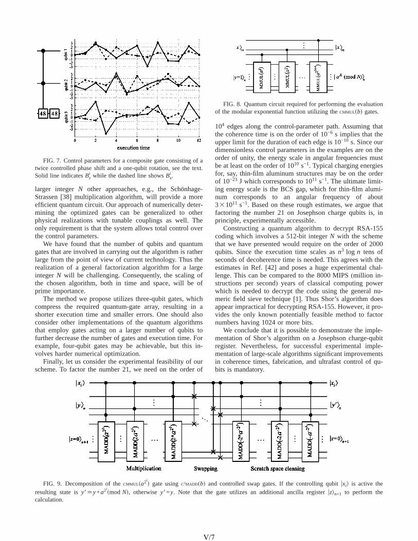
larger integerN other approaches, e.g., the Schönhage-Strassen[38] multiplication algorithm, will provide a moreefficient quantum circuit. Our approach of numerically deter-mining the optimized gates can be generalized to otherphysical realizations with tunable couplings as well. Theonly requirement is that the system allows total control overthe control parameters.
We have found that the number of qubits and quantumgates that are involved in carrying out the algorithm is ratherlarge from the point of view of current technology. Thus therealization of a general factorization algorithm for a largeintegerN will be challenging. Consequently, the scaling ofthe chosen algorithm, both in time and space, will be ofprime importance.
The method we propose utilizes three-qubit gates, whichcompress the required quantum-gate array, resulting in ashorter execution time and smaller errors. One should alsoconsider other implementations of the quantum algorithmsthat employ gates acting on a larger number of qubits tofurther decrease the number of gates and execution time. Forexample, four-qubit gates may be achievable, but this in-volves harder numerical optimization.
Finally, let us consider the experimental feasibility of ourscheme. To factor the number 21, we need on the order of
104 edges along the control-parameter path. Assuming thatthe coherence time is on the order of 10−6 s implies that theupper limit for the duration of each edge is 10−10 s. Since ourdimensionless control parameters in the examples are on theorder of unity, the energy scale in angular frequencies mustbe at least on the order of 1010 s−1. Typical charging energiesfor, say, thin-film aluminum structures may be on the orderof 10−23 J which corresponds to 1011 s−1. The ultimate limit-ing energy scale is the BCS gap, which for thin-film alumi-num corresponds to an angular frequency of about331011 s−1. Based on these rough estimates, we argue thatfactoring the number 21 on Josephson charge qubits is, inprinciple, experimentally accessible.
Constructing a quantum algorithm to decrypt RSA-155coding which involves a 512-bit integerN with the schemethat we have presented would require on the order of 2000qubits. Since the execution time scales asn3 log n tens ofseconds of decoherence time is needed. This agrees with theestimates in Ref.[42] and poses a huge experimental chal-lenge. This can be compared to the 8000 MIPS(million in-structions per second) years of classical computing powerwhich is needed to decrypt the code using the general nu-meric field sieve technique[1]. Thus Shor’s algorithm doesappear impractical for decrypting RSA-155. However, it pro-vides the only known potentially feasible method to factornumbers having 1024 or more bits.
We conclude that it is possible to demonstrate the imple-mentation of Shor’s algorithm on a Josephson charge-qubitregister. Nevertheless, for successful experimental imple-mentation of large-scale algorithms significant improvementsin coherence times, fabrication, and ultrafast control of qu-bits is mandatory.
FIG. 8. Quantum circuit required for performing the evaluationof the modular exponential function utilizing theCMMULsbd gates.
FIG. 9. Decomposition of theCMMULsa2id gate usingC2MADDsbd and controlled swap gates. If the controlling qubituxil is active the
resulting state isy8;y+a2ismod Nd, otherwisey8=y. Note that the gate utilizes an additional ancilla registeruzln+1 to perform the
calculation.
FIG. 7. Control parameters for a composite gate consisting of atwice controlled phase shift and a one-qubit rotation, see the text.Solid line indicatesBz
i while the dashed line showsBxi .
IMPLEMENTING SHOR’S ALGORITHM ON JOSEPHSON… PHYSICAL REVIEW A 70, 012319(2004)
012319-7
V/7

Note added.Recently, it was brought to our attention thata similar circuit implementing Shor’s algorithm has beenconstructed for a linear nearest-neighborsLNNd qubit array[43] independent of any specific physical realization.
ACKNOWLEDGMENTS
J.J.V. thanks the Foundation of Technology(TES, Fin-land) and the Emil Aaltonen Foundation for financial sup-port. M.N. thanks the Helsinki University of Technology forfinancial support; he is grateful for partial support of a Grant-in-Aid from the MEXT and JSPS, Japan(Project Nos.14540346 and 13135215). The research has been supportedin the Materials Physics Laboratory at HUT by Academy ofFinland through Research Grants in Theoretical MaterialsPhysics (No. 201710) and in Quantum Computation(No.206457). We also thank Robert Joynt, Jani Kivioja, MikkoMöttönen, Jukka Pekola, Ville Bergholm, and Olli-MattiPenttinen for enlightening discussions. We are grateful toCSC—Scientific Computing Ltd., Finland for parallel com-puting resources.
APPENDIX A: CONSTRUCTION OF A QUANTUMCIRCUIT
Here we represent the construction of a quantum circuitneeded for an evaluation of the modular exponential functionaxsmod Nd. We assume the values ofa andN to be constantintegers coprime to each other. This approach takes advan-tage of the fast powers trick, see Eq.(A1) below, as well asthe construction of a multiplier suggested by Beauregard[31], which in part employs the adder of Draper[32].
The modular exponential function can be expressed interms of modular products:
ax ; pi=0
2n−1
„a2ixismod Nd…smod Nd, sA1d
where we have used the binary expansionx=20x0+21x1+2n−1xn−1, xi P h0,1j. Note that the number of factors in Eq.(A1) grows only linearly for increasingn. The longhandmultiplication is based on the relation
a2ix ; o
k=0
2n−1
„a2i2kxksmod Nd…smod Nd, sA2d
which again involves only a linear number of terms.Equation(A1) yields a decomposition of the modular ex-
ponential function into controlled modular multiplicationgatesfCMMULsa2i
dg, see Fig. 8. According to Eq.(A2), each of
theMMUL sa2id gates can be implemented with the sequence of
the modular adders, see Fig. 9. Since this decomposition ofCMMULsa2i
d requires extra space for the intermediate results,we are forced to introduce a scratch spaceuzln+1 into thesetup. Initially, we setuzln+1= u0ln+1. Moreover, we must resetthe extra scratch space after each multiplication. This is ac-complished by multiplication with the inverse elementb−1
whereb=a2i. Let us consider how the gateCMMULsbd works:
uxlu0l → uxlu0 + bxsmod Ndl sproductd
→ bxsmod Nduxl sswapd
→ ubxsmod Ndlux + s− b−1d„bxsmod Nd…l
= bxsmod Ndu0l sresultd.
Euler’s totient theorem guarantees that for everyb which iscoprime toN, a modular inverseb−1PN exists. Furthermore,the extended Euclidean algorithm provides an efficient wayto find the numerical value forb−1.
Figure 10 presents the decomposition of theC2MADDsbdgate sbPNd using adders in the Fourier space. The idea isfirst to calculatez8=z+b−N. If z8,0 the ancillaa, which isinitially zero, is flipped andN is added toz8 yielding z8=z+b. The rest of the circuit is needed to reseta to zero.
The circuit simplifies when multipleC2MADDsbd gates areapplied since the final QFT* will cancel against the initialQFT of two consecutive gates. This is taken into account incounting the total number of gates and in Fig. 5. An obvious
FIG. 10. Decomposition of theC2MADDsbd gate into elementary gates, QFT gates, and additions in the Fourier basis(C2ADD). The asteriskstands for a Hermitian conjugate; it corresponds to a gate for subtraction. The gate takes an input valuez,Nø2n and yieldsuz8ln+1= uz+bsmod Ndln+1 if the control qubitsxi =1 andyj =1. Otherwiseuz8ln+1= uzln+1. The ancilla qubitual is one if z+b.N and zero otherwise.
FIG. 11. Quantum circuit for ann-qubit Fourier transformation.Here H stands for the Hadamard gate. The controlled phase-shiftgates are labeled with the numbersk which correspond to the phaseshifts ei2pk/2n
. Note the reversed order of the qubits on the right-hand side.
VARTIAINEN et al. PHYSICAL REVIEW A 70, 012319(2004)
012319-8
V/8

drawback of this implementation is the need for a number ofQFT gates. However, we need to introduce only one ancillaqubit ual.
The decomposition of the gateC2MADDsbd consists oftwice controlled adders,sn+1d-qubit QFTs, one-qubitNOTS,andCNOTS. The decomposition of a QFT-gate into one- andtwo-qubit gates[2] is represented in Fig. 11. Since Fourierspace is utilized, theC2ADDsbd gates can be implemented[32]using controlled2 phase shifts. The quantum gate sequencefor an adder working in the Fourier space is depicted in Fig.12. The values of the phase shifts for the gateC2ADDsbd are
given bye2pif j/2n, wheref j =2jb.
Finally, we are in the position to perform the unitarytransformation which implements the modular exponentialfunction using only one-, two- and three-qubit gates. If thethree-qubit gates are not available, further decompositioninto one- and two-qubit gates is needed, see Ref.[24]. Forinstance, each three-qubit twice controlledU gate decom-poses into five two-qubit gates and each Fredkin gate takesseven two-qubit gates to implement.
APPENDIX B: DERIVATION OF THE HAMILTONIAN
1. The Lagrangian
Consider a homogenous array of mesoscopic supercon-ducting islands as an idealized model of a quantum register,see Fig. 2. The basis states of the qubit correspond to eitherzero or one extra Cooper pair residing on the superconduct-ing island, denoted byu0l and u1l, respectively. Each of theislands, or Cooper-pair boxes, is capacitively coupled to agate voltage,Vg
i . In addition, they are coupled to a supercon-ducting lead through a mesoscopic SQUID with identicaljunctions, each having the same Josephson energyEJ/2 andcapacitanceCJ/2. All these qubits are then coupled in paral-lel with an inductor,L. The lowest relevant energy scale isset by the thermal energykBT and the highest scale by theBCS gapDBCS.
We assume that the gate voltageVgi and the time-
dependent fluxFi through each SQUID can be controlledexternally. The fluxFi may be controlled with an adjustablecurrentI i through an external coil, see the dotted line in Fig.2(a). In this setup, the Cooper pairs can tunnel coherently toa superconducting electrode. We denote the time-integral ofvoltage, or difference in flux units, over the left junction ofthe ith SQUID byfi and the flux through the inductor byw.The phase difference in flux units over the rightmost junction
is fi −Fi. We take the positive direction for flux to be di-rected outward normal to the page.
We adoptfi andw as the dynamical variables, whereasFiand Vg
i are external adjustable parameters. With the help ofelementary circuit analysis[44], we obtain the Lagrangianfor the qubit register
L =1
2oi=1
M FCJ
2fi
2 +CJ
2sfi − Fid2 + Cgsfi + w − Vg
i d2 − G w2
2L
+1
2oi=1
M FEJ cosS2e
"fiD + EJ cosS2e
"sfi − FidDG . sB1d
We now perform the following changes of variables
fi → fi +Fi
2−
Cg
CJ + Cgw, sB2d
which yields
L =1
2oi=1
M FsCJ + Cgdfi2 − 2CgSVg
i −Fi
2Dfi
+ EJ cosSpFi
F0DcosS2e
"fi −
2pCqb
F0CJwDG +
1
2MCqbw
2
− oi=1
M
CqbSVgi −
Fi
2Dw −
w2
2L+ const. sB3d
Above, F0=h/2e is the flux quantum andCqb=CJCg/ sCJ
+Cgd is the qubit capacitance in theLC circuit. Note that theeffective Josephson energy of each SQUID can now betuned. We denote this tunable energy parameter in Eq.(B3)as
EJsFid = EJ cosSpFi
F0D . sB4d
The canonical momenta are given byQ=]L /]w and qi
=]L /]fi. We interpretQ as the charge on the collectivecapacitor formed by the whole qubit register, whereasqi isthe charge on theith island. Note that the chargeqi is relatedto the numberni of Cooper pairs on the island throughqi=−2eni.
2. The Hamiltonian
We are now in the position to write down the Hamiltonianfor the quantum register. We will also immediately replacethe canonical variables by operators in order to quantize theregister. Moreover, we will employ the number of excessCooper pairsni on the island and the superconducting phasedifference instead of the usual quantum-mechanical conju-gates. We will also change to the more common phase dif-ferenceui related tofi throughui =s2e/"dfi. Hence the rel-evant commutation relations arefui ,nig=−i and fw ,Qg= i".All the other commutators vanish. Using the Legendre trans-formation
FIG. 12. Quantum circuit for the twice controlled addition of aclassical numberb into the quantum registeruzln+1 in the Fourierbasis. The twice controlled phase-shift gates serve to yield the phaseshift e2pifk/2
nprovided that the control qubitsuxil anduyjl are active.
IMPLEMENTING SHOR’S ALGORITHM ON JOSEPHSON… PHYSICAL REVIEW A 70, 012319(2004)
012319-9
V/9

H = Qw + oi=1
M
qifi − L sB5d
we obtain
H = oi=1
M F2e2sni − ngi d2
CJ + Cg− EJsFidcosSui −
2pCqb
F0CJwDG
+sQ + Qgd2
2MCqb+
w2
2L. sB6d
We have denoted the effective gate charge by
ngi =
Cg
2eSVg
i −Fi
2D sB7d
and
Qg = oi=1
M
CqpSVgi −
Fi
2D . sB8d
In addition to the usual voltage contribution, the time depen-dence of the flux also plays a role. In practice, the rates ofchange of the flux are negligible in comparison to the volt-ages and this term may safely be dropped.
The Hamiltonian in Eq.(B6) describes the register of qu-bits sni ,fid coupled to a quantum-mechanicalLC resonator,i.e., a harmonic oscillatorsQ,wd. We will now assume thatthe rms fluctuations ofw are small compared to the fluxquantumF0 and also that the harmonic oscillator has a suf-ficiently high frequency, such that it stays in the ground state.The first assumption implies that
cosSui −2pCqb
F0CJwD < cosui +
2pCqb
F0CJw sin ui . sB9d
The second assumption will cause an effective coupling be-tween the qubits. Namely, the Hamiltonian may now be re-written in the more suggestive form
H < oi=1
M F2e2sni − ngi d2
CJ + Cg− EJsFidcosuiG +
sQ + Qgd2
2MCqb
+sw − w2d
2L−
w2
2L, sB10d
where the operatorw is given by
w =2pLCqb
F0CJoi=1
M
EJsFidsin ui . sB11d
We now see from Eq.(B10) that in the high-frequency limitthe harmonic oscillator is effectively decoupled from the qu-bit register. The effect of the qubit register is thus to redefinethe minimum of the potential energy for the oscillator. Thisdoes not affect the spectrum of the oscillator, since it willadiabatically follow its ground state in the low-temperaturelimit. We may therefore trace over the degrees of freedom ofthe harmonic oscillator and the harmonic-oscillator energywill merely yield a zero-point energy contribution,"vLC/2.The effective Hamiltonian describing the dynamics of thecoupled qubit register alone is thus
H < oi=1
M F2e2sni − ngi d2
CJ + Cg− EJsFidcosuiG
−2p2LCqb
2
F02CJ
2 Soi=1
M
EJsFidsin uiD2
. sB12d
This result is in agreement with the one presented in Ref.[20]. We conclude that theLC-oscillator has created a virtualcoupling between the qubits.
For the purposes of quantum computing, it is convenientto truncate the Hilbert space such that each Cooper-pair boxwill have only two basis states. In the limit of a high charg-ing energyEC=2e2/ sCg+CJd relative to the Josephson en-ergy EJ, we may argue that in the region 0øng
i ø1 only thestates withni =0,1 can be occupied. We use the vector rep-resentation for these states, in whichu0li =s1 0di
T and u1li
=s0 1diT.
The basis states of the Hilbert space are orthogonalkkue±iuull=dk,l71. Hence, in this two-state approximation,cosui =
12sx
i and sinui =12sy
i , where, e.g.,
Finally, omitting the constant terms, we obtain the Hamil-tonian in the Pauli-matrix representation
Hqb = oi=1
M F−EC
2s1 − 2ng
i dszi −
EJsFid2
sxi G
−p2L
F02 SCqb
CJD2
oi=1
M
oj=i+1
M
EJsFidEJsF jdsyi
^ syj ,
sB13d
which results in Eqs.(2) and (3) of the main text.
[1] A. Galindo and M. A. Martín-Delgado, Rev. Mod. Phys.74,347 (2002).
[2] M. A. Nielsen and I. L. Chuang,Quantum Computation andQuantum Information(Cambridge University Press, Cam-bridge, 2000).
[3] P. W. Shor, inProceedings of the 35th Annual Symposium onFoundations of Computer Science, edited by S. Goldwasser(IEEE Computer Society Press, Los Alamitos, CA, 1994), Vol.124.
[4] L. K. Grover, Phys. Rev. Lett.79, 325 (1997).
VARTIAINEN et al. PHYSICAL REVIEW A 70, 012319(2004)
012319-10
V/10
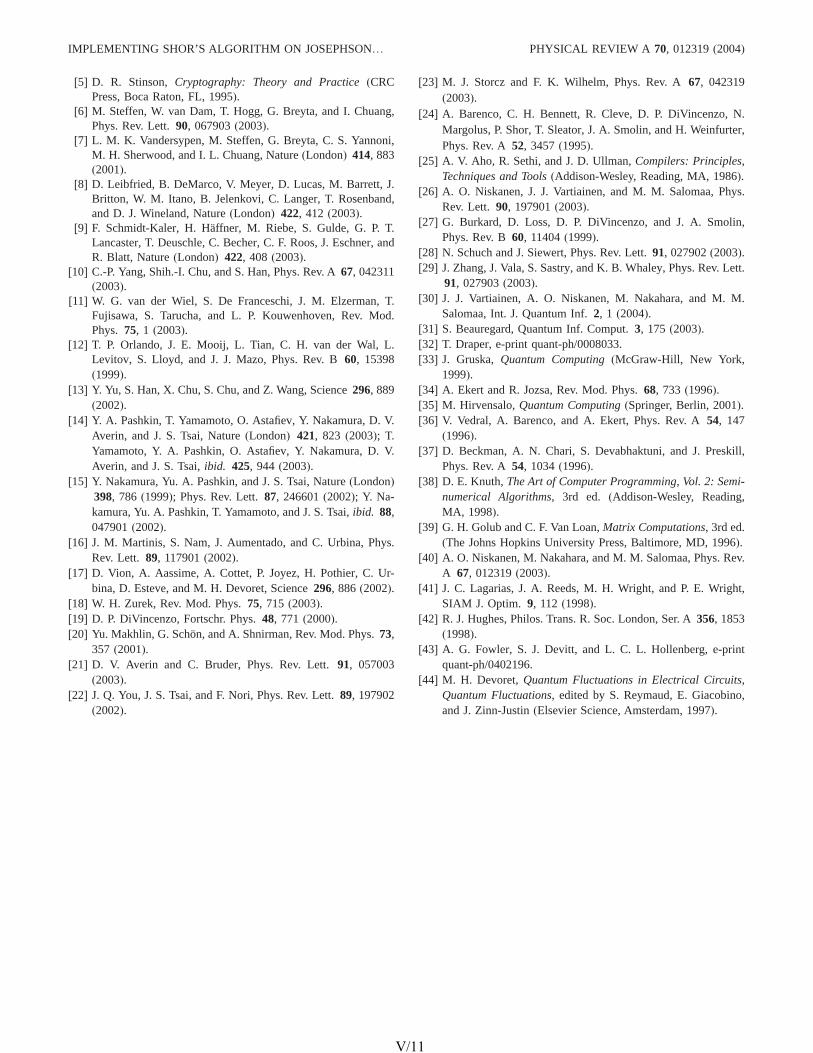
[5] D. R. Stinson,Cryptography: Theory and Practice(CRCPress, Boca Raton, FL, 1995).
[6] M. Steffen, W. van Dam, T. Hogg, G. Breyta, and I. Chuang,Phys. Rev. Lett.90, 067903(2003).
[7] L. M. K. Vandersypen, M. Steffen, G. Breyta, C. S. Yannoni,M. H. Sherwood, and I. L. Chuang, Nature(London) 414, 883(2001).
[8] D. Leibfried, B. DeMarco, V. Meyer, D. Lucas, M. Barrett, J.Britton, W. M. Itano, B. Jelenkovi, C. Langer, T. Rosenband,and D. J. Wineland, Nature(London) 422, 412 (2003).
[9] F. Schmidt-Kaler, H. Häffner, M. Riebe, S. Gulde, G. P. T.Lancaster, T. Deuschle, C. Becher, C. F. Roos, J. Eschner, andR. Blatt, Nature(London) 422, 408 (2003).
[10] C.-P. Yang, Shih.-I. Chu, and S. Han, Phys. Rev. A67, 042311(2003).
[11] W. G. van der Wiel, S. De Franceschi, J. M. Elzerman, T.Fujisawa, S. Tarucha, and L. P. Kouwenhoven, Rev. Mod.Phys. 75, 1 (2003).
[12] T. P. Orlando, J. E. Mooij, L. Tian, C. H. van der Wal, L.Levitov, S. Lloyd, and J. J. Mazo, Phys. Rev. B60, 15398(1999).
[13] Y. Yu, S. Han, X. Chu, S. Chu, and Z. Wang, Science296, 889(2002).
[14] Y. A. Pashkin, T. Yamamoto, O. Astafiev, Y. Nakamura, D. V.Averin, and J. S. Tsai, Nature(London) 421, 823 (2003); T.Yamamoto, Y. A. Pashkin, O. Astafiev, Y. Nakamura, D. V.Averin, and J. S. Tsai,ibid. 425, 944 (2003).
[15] Y. Nakamura, Yu. A. Pashkin, and J. S. Tsai, Nature(London)398, 786 (1999); Phys. Rev. Lett.87, 246601(2002); Y. Na-kamura, Yu. A. Pashkin, T. Yamamoto, and J. S. Tsai,ibid. 88,047901(2002).
[16] J. M. Martinis, S. Nam, J. Aumentado, and C. Urbina, Phys.Rev. Lett. 89, 117901(2002).
[17] D. Vion, A. Aassime, A. Cottet, P. Joyez, H. Pothier, C. Ur-bina, D. Esteve, and M. H. Devoret, Science296, 886 (2002).
[18] W. H. Zurek, Rev. Mod. Phys.75, 715 (2003).[19] D. P. DiVincenzo, Fortschr. Phys.48, 771 (2000).[20] Yu. Makhlin, G. Schön, and A. Shnirman, Rev. Mod. Phys.73,
357 (2001).[21] D. V. Averin and C. Bruder, Phys. Rev. Lett.91, 057003
(2003).[22] J. Q. You, J. S. Tsai, and F. Nori, Phys. Rev. Lett.89, 197902
(2002).
[23] M. J. Storcz and F. K. Wilhelm, Phys. Rev. A67, 042319(2003).
[24] A. Barenco, C. H. Bennett, R. Cleve, D. P. DiVincenzo, N.Margolus, P. Shor, T. Sleator, J. A. Smolin, and H. Weinfurter,Phys. Rev. A52, 3457(1995).
[25] A. V. Aho, R. Sethi, and J. D. Ullman,Compilers: Principles,Techniques and Tools(Addison-Wesley, Reading, MA, 1986).
[26] A. O. Niskanen, J. J. Vartiainen, and M. M. Salomaa, Phys.Rev. Lett. 90, 197901(2003).
[27] G. Burkard, D. Loss, D. P. DiVincenzo, and J. A. Smolin,Phys. Rev. B60, 11404(1999).
[28] N. Schuch and J. Siewert, Phys. Rev. Lett.91, 027902(2003).[29] J. Zhang, J. Vala, S. Sastry, and K. B. Whaley, Phys. Rev. Lett.
91, 027903(2003).[30] J. J. Vartiainen, A. O. Niskanen, M. Nakahara, and M. M.
Salomaa, Int. J. Quantum Inf.2, 1 (2004).[31] S. Beauregard, Quantum Inf. Comput.3, 175 (2003).[32] T. Draper, e-print quant-ph/0008033.[33] J. Gruska,Quantum Computing(McGraw-Hill, New York,
1999).[34] A. Ekert and R. Jozsa, Rev. Mod. Phys.68, 733 (1996).[35] M. Hirvensalo,Quantum Computing(Springer, Berlin, 2001).[36] V. Vedral, A. Barenco, and A. Ekert, Phys. Rev. A54, 147
(1996).[37] D. Beckman, A. N. Chari, S. Devabhaktuni, and J. Preskill,
Phys. Rev. A54, 1034(1996).[38] D. E. Knuth,The Art of Computer Programming, Vol. 2: Semi-
numerical Algorithms, 3rd ed. (Addison-Wesley, Reading,MA, 1998).
[39] G. H. Golub and C. F. Van Loan,Matrix Computations, 3rd ed.(The Johns Hopkins University Press, Baltimore, MD, 1996).
[40] A. O. Niskanen, M. Nakahara, and M. M. Salomaa, Phys. Rev.A 67, 012319(2003).
[41] J. C. Lagarias, J. A. Reeds, M. H. Wright, and P. E. Wright,SIAM J. Optim. 9, 112 (1998).
[42] R. J. Hughes, Philos. Trans. R. Soc. London, Ser. A356, 1853(1998).
[43] A. G. Fowler, S. J. Devitt, and L. C. L. Hollenberg, e-printquant-ph/0402196.
[44] M. H. Devoret,Quantum Fluctuations in Electrical Circuits,Quantum Fluctuations, edited by S. Reymaud, E. Giacobino,and J. Zinn-Justin(Elsevier Science, Amsterdam, 1997).
IMPLEMENTING SHOR’S ALGORITHM ON JOSEPHSON… PHYSICAL REVIEW A 70, 012319(2004)
012319-11
V/11
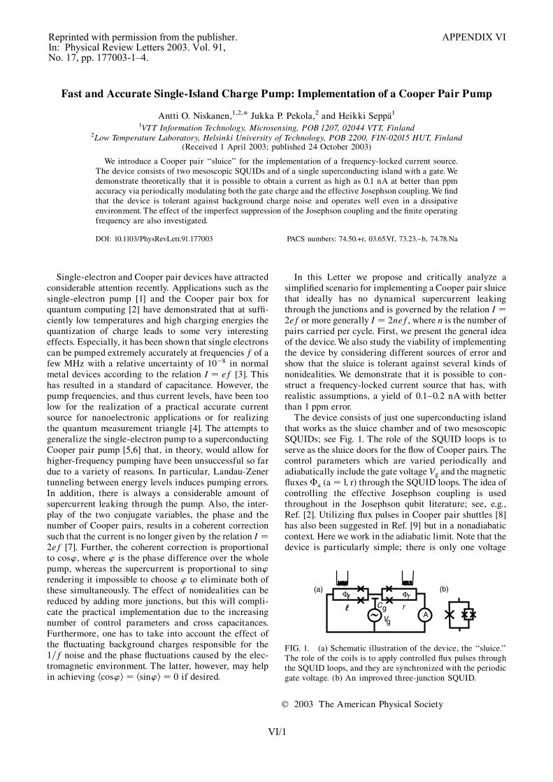
Fast and Accurate Single-Island Charge Pump: Implementation of a Cooper Pair Pump
Antti O. Niskanen,1,2,* Jukka P. Pekola,2 and Heikki Seppa1
1VTT Information Technology, Microsensing, POB 1207, 02044 VTT, Finland2Low Temperature Laboratory, Helsinki University of Technology, POB 2200, FIN-02015 HUT, Finland
(Received 1 April 2003; published 24 October 2003)
We introduce a Cooper pair ‘‘sluice’’ for the implementation of a frequency-locked current source.The device consists of two mesoscopic SQUIDs and of a single superconducting island with a gate. Wedemonstrate theoretically that it is possible to obtain a current as high as 0.1 nA at better than ppmaccuracy via periodically modulating both the gate charge and the effective Josephson coupling. We findthat the device is tolerant against background charge noise and operates well even in a dissipativeenvironment. The effect of the imperfect suppression of the Josephson coupling and the finite operatingfrequency are also investigated.
DOI: 10.1103/PhysRevLett.91.177003 PACS numbers: 74.50.+r, 03.65.Vf, 73.23.–b, 74.78.Na
Single-electron and Cooper pair devices have attractedconsiderable attention recently. Applications such as thesingle-electron pump [1] and the Cooper pair box forquantum computing [2] have demonstrated that at suffi-ciently low temperatures and high charging energies thequantization of charge leads to some very interestingeffects. Especially, it has been shown that single electronscan be pumped extremely accurately at frequencies f of afew MHz with a relative uncertainty of 10�8 in normalmetal devices according to the relation I � ef [3]. Thishas resulted in a standard of capacitance. However, thepump frequencies, and thus current levels, have been toolow for the realization of a practical accurate currentsource for nanoelectronic applications or for realizingthe quantum measurement triangle [4]. The attempts togeneralize the single-electron pump to a superconductingCooper pair pump [5,6] that, in theory, would allow forhigher-frequency pumping have been unsuccessful so fardue to a variety of reasons. In particular, Landau-Zenertunneling between energy levels induces pumping errors.In addition, there is always a considerable amount ofsupercurrent leaking through the pump. Also, the inter-play of the two conjugate variables, the phase and thenumber of Cooper pairs, results in a coherent correctionsuch that the current is no longer given by the relation I �2ef [7]. Further, the coherent correction is proportionalto cos’, where ’ is the phase difference over the wholepump, whereas the supercurrent is proportional to sin’rendering it impossible to choose ’ to eliminate both ofthese simultaneously. The effect of nonidealities can bereduced by adding more junctions, but this will compli-cate the practical implementation due to the increasingnumber of control parameters and cross capacitances.Furthermore, one has to take into account the effect ofthe fluctuating background charges responsible for the1=f noise and the phase fluctuations caused by the elec-tromagnetic environment. The latter, however, may helpin achieving hcos’i � hsin’i � 0 if desired.
In this Letter we propose and critically analyze asimplified scenario for implementing a Cooper pair sluicethat ideally has no dynamical supercurrent leakingthrough the junctions and is governed by the relation I �2ef or more generally I � 2nef, where n is the number ofpairs carried per cycle. First, we present the general ideaof the device. We also study the viability of implementingthe device by considering different sources of error andshow that the sluice is tolerant against several kinds ofnonidealities. We demonstrate that it is possible to con-struct a frequency-locked current source that has, withrealistic assumptions, a yield of 0.1–0.2 nA with betterthan 1 ppm error.
The device consists of just one superconducting islandthat works as the sluice chamber and of two mesoscopicSQUIDs; see Fig. 1. The role of the SQUID loops is toserve as the sluice doors for the flow of Cooper pairs. Thecontrol parameters which are varied periodically andadiabatically include the gate voltage Vg and the magneticfluxes �a (a � l; r) through the SQUID loops. The idea ofcontrolling the effective Josephson coupling is usedthroughout in the Josephson qubit literature; see, e.g.,Ref. [2]. Utilizing flux pulses in Cooper pair shuttles [8]has also been suggested in Ref. [9] but in a nonadiabaticcontext. Here we work in the adiabatic limit. Note that thedevice is particularly simple; there is only one voltage
AVg
Φ ΦrrCg
(a) (b)
FIG. 1. (a) Schematic illustration of the device, the ‘‘sluice.’’The role of the coils is to apply controlled flux pulses throughthe SQUID loops, and they are synchronized with the periodicgate voltage. (b) An improved three-junction SQUID.
P H Y S I C A L R E V I E W L E T T E R S week ending24 OCTOBER 2003VOLUME 91, NUMBER 17
177003-1 0031-9007=03=91(17)=177003(4)$20.00 © 2003 The American Physical Society 177003-1
VI/1
Reprinted with permission from the publisher. APPENDIX VIIn: Physical Review Letters 2003. Vol. 91,No. 17, pp. 177003-1–4.

gate to adjust. The current through the sluice is given bythe time integral of the expectation value of the currentoperator of either of the two SQUIDs. The dynamics isgoverned by the Schrodinger equation and the Hamil-tonian of the device is (in the case of identical junctions)
HH � 2e2
2CJ � Cg�nn� ng�2 � Er
J
���r
�0
�cos��� ’=2�
� ElJ
���l
�0
�cos�’=2���: (1)
Here CJ=2 is the capacitance of a single junction, Cg is thecapacitance of the gate, ng � CgVg=2e is the gate chargein 2e units, �0 � h=2e, and ’ is the phase differenceover the sluice. Furthermore, Ea
J�� �a
�0� � Emax
J cos�� �a
�0�
(a � l; r) denotes the effective flux-dependent signedJosephson energy of the left and the right SQUID, re-spectively. The Josephson energy of a single junction isthus Emax
J =2. The factor EC � �2e2�=�2CJ � Cg� is thecharging energy. The quantum mechanical conjugate var-iables are the number of Cooper pairs on the island nn andthe superconducting phase �. They obey the canonicalcommutation relation �nn; �� � i. The case of nonidenti-cal junctions is modeled below by not allowing theJosephson energy to vanish during the cycle. We notethat it is possible to use more complicated SQUIDs [seeFig. 1(b)] for which one of the junctions is replaced by aSQUID biased with a static field to match the EJ of theother half when �0=2 threads the primary loop. Self-inductance may be ignored for two junctions (othersources of error dominate) but for the three-junctiondesign the self-inductance sets a limit for suppression at�LIC=�0 where IC � 2�EJ=�0. An achievable value forthis could be 10�3. The current operator of the, say, rightSQUID is
Ir � 2e�hErJ
���r
�0
�sin��� ’=2�: (2)
The total charge flowing through the system over onecycle has two components in the adiabatic limit [7],namely, the contribution from the dynamical supercur-rent
Qs �Z tcycle
0h0;q�t�jIrj0;q�t�idt; (3)
and the pumped charge (� is the loop in parameter space)
Qp � 2 �h Im
"Xn�0
I�
h0;qjIrjn;qiE0�q� � En�q� hn;qjrqj0;qi dq
#:
(4)
We have denoted above the control parameters collec-tively by the vector q which is varied in time. In thepresent context q � �ng; Er
J; ElJ�T . Because of the adiaba-
ticity criterion, the sluice stays at all times in the groundstate with negligible Zener tunneling. The nth eigenstate
at the point q is denoted by jn;qi and the energy eigen-value by En�q�.
Figure 2 illustrates a model control-parameter se-quence. Note that the SQUIDs are biased in such amanner that one door is always closed, such that thedynamical contribution of Eq. (3) vanishes. Moreover,the signal is designed such that the system Hamiltonian(1) is always nondegenerate. This validates the use ofEq. (4). Varying just the gate voltage would lead to adegeneracy at ng � 0:5, but because just one of the doorsis open at this point, the problem is resolved. The sluice isideally a switchable Cooper pair box. During the first halfof the sequence one of the SQUIDs works as a Josephsonjunction while the other is effectively a capacitor. Thenthe roles are exchanged. It is easy to see that this sequenceleads to the transport of exactly one Cooper pair throughthe sluice per cycle. In the beginning of the sequence thesystem is in the eigenstate of charge (zero pairs) due to thefact that the effective Josephson couplings are set to zero.In the middle of the sequence when both doors are againclosed, the island is in the eigenstate of charge but nowwith one extra Cooper pair. The Cooper pair has tunneledthrough the right SQUID since the left one was closed.Finally, in the end of pulse the system is again at theeigenstate of charge with zero Cooper pairs and thecharge must have gone through the left SQUID.Repeating this sequence results in I � 2ef, where f �1=tcycle. The form of the pulse may also be generalized forthe purpose of allowing n Cooper pairs to flow throughthe sluice over tcycle, thus increasing the current to I �2nef, simply by operating between ng � 0 and ng � n.
Assuming that the SQUIDs can be closed to a highdegree renders the system almost entirely insensitive tothe actual operating point of voltage. Instead of operating
0 0.2 0.4 0.6 0.8 10
0.5
1
t /t cycle
n g
0 0.2 0.4 0.6 0.8 10
0.5
1
t /t cycle
E J r
/ E J m
ax
0 0.2 0.4 0.6 0.8 10
0.5
1
t /t cycle
E J l
/ E J m
ax
FIG. 2. Pulse sequence for pumping a single Cooper pairthrough the sluice. The exact form of the pulses is not crucialas long as the synchronization is maintained. The gate charge(or voltage) pulse, which is a shifted harmonic one here, maybe generalized to have a larger amplitude and thus a largernumber of pairs could be pumped.
P H Y S I C A L R E V I E W L E T T E R S week ending24 OCTOBER 2003VOLUME 91, NUMBER 17
177003-2 177003-2
VI/2
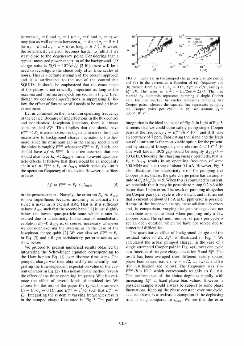
between ng � 0 and ng � 1 (or ng � 0 and ng � n) wemay just as well operate between ng � � and ng � �� 1(or ng � � and ng � n� �) as long as � � 1
2 . However,the adiabaticity criterion becomes harder to fulfill if westart close to the degeneracy point. Considering that atypical measured power spectrum of the background 1=fcharge noise is S�f� � 10�8e2=f [2,10], there will be aneed to reconfigure the sluice only after time scales ofhours. This is a definite strength of the present approachand it is attributable to the use of the controllableSQUIDs. It should be emphasized that the exact shapeof the pulses is not crucially important as long as themaxima and minima are synchronized as in Fig. 2. Eventhough we consider imperfections in suppressing EJ be-low, the effect of flux noise still needs to be studied in anexperiment.
Let us comment on the maximum operating frequencyof the device. Because of imperfections in the flux controland nonidentical Josephson junctions, there is alwayssome residual Eres
J . This implies that one should haveEmaxJ <EC to avoid excess leakage and to make the sluice
insensitive to background charge fluctuations. Further-more, since the minimum gap in the energy spectrum ofthe sluice is roughly Emax
J whenever EmaxJ EC holds, one
should have hf � EmaxJ . It is often asserted that one
should also have EC � �BCS in order to avoid quasipar-ticle effects. It follows that there would be an inequalitychain hf � Emax
J <EC � �BCS which seriously limitsthe operation frequency of the device. However, it sufficesto have
hf � EmaxJ � EC & �BCS (5)
in the present context. Namely, the criterion EC � �BCS
is now superfluous because, assuming adiabaticity, thesluice is never in its excited state. That is, it is sufficientto have �BCS such that the second band [11] is just slightlybelow the lowest quasiparticle state which cannot beexcited due to adiabaticity. In the case of nonadiabaticevolution EC � �BCS is, of course, necessary wheneverwe consider exciting the system, as in the case of theJosephson charge qubit [2]. We can also set Emax
J � EC
in Eq. (5) and still get satisfactory performance as weshow below.
We proceed to present numerical results obtained byintegrating the Schrodinger equation corresponding tothe Hamiltonian Eq. (1) over discrete time steps. Thepumped charge was then obtained by numerically inte-grating the time-dependent expectation value of the cur-rent operator in Eq. (2). This nonadiabatic method revealsthe effect of the finite operating frequency. We also esti-mate the effect of several kinds of nonidealities. Wechoose for the rest of the paper the typical parametersCJ � C, Cg � 0:1C, and Emax
J � e2=C such that EmaxJ �
EC. Integrating the system at varying frequencies resultsin the pumped charge illustrated in Fig. 3. The path of
integration is the ideal sequence of Fig. 2. In light of Fig. 3,it seems that we could quite safely pump single Cooperpairs at the frequency f � Emax
J = �h 10�3 and still havean accuracy of 7 ppm. Fabricating the island and the leadsout of aluminum is the most viable option for the present,and by standard lithography one obtains C< 10�15 fF.The well known BCS gap would be roughly �BCS=h �50 GHz. Choosing the charging energy optimally, that is,EC & �BCS, results in an operating frequency of some300 MHz and a current of about 0.1 nA. However, Fig. 3also illustrates the adiabaticity error for pumping fiveCooper pairs; that is, the gate charge pulse has an ampli-tude of Cg�Vg=2e � 5. When this is converted to current,we conclude that it may be possible to pump 0.2 nA withbetter than 1 ppm error. The result of pumping altogetherten Cooper pairs per cycle is also shown, and it turns outthat a current of about 0.1 nA at 0.1 ppm error is possible.Ramps of the Josephson energy cause adiabaticity errorsand, in comparison, varying the gate voltage does notcontribute as much at least when pumping only a fewCooper pairs. The optimum number of pairs per cycle isyet an open question which we have not solved due tonumerical difficulties.
The quantitative effect of background charge and theresidual value of EJ, Eres
J , is illustrated in Fig. 4. Wecalculated the actual pumped charge, in the case of asingle attempted Cooper pair in Fig. 4(a), over one cycleas a function of the gate charge deviation � and Eres
J . Theresult has been averaged over different evenly spacedphase bias values, namely, ’ � �=2, �, 3�=2, and 2�(for justification see below). The frequency was f �EmaxJ = �h 10�4 which corresponds roughly to 0.1 nA.
The performance of the sluice degrades rapidly withincreasing Eres
J at fixed phase bias values. However, aphysical sample would always be subject to some phasefluctuations. Keeping the phase constant over one cycle,as done above, is a realistic assumption if the dephasingtime is long compared to tcycle. We see that the error
10−4
10− 3
10− 2
10− 8
10− 6
10− 4
10−2
f/fJ
ε
10− 2
10− 1
100
10− 8
10− 6
10− 4
10− 2
I (nA)
1 pair5 pairs10 pairs
a) b)
ε
FIG. 3. Error (a) in the pumped charge over a single periodand (b) in the current as a function of (a) frequency and(b) current. Here CJ � C, Cg � 0:1C, Emax
J � e2=C, and fJ �EmaxJ = �h. The error is " � 1�QP=2ne � �I=I. The line
marked by diamonds represents pumping a single Cooperpair, the line marked by circles represents pumping fiveCooper pairs, whereas the squared line represents pumpingten Cooper pairs per cycle. In (b) we assume fJ �300 109 s�1.
P H Y S I C A L R E V I E W L E T T E R S week ending24 OCTOBER 2003VOLUME 91, NUMBER 17
177003-3 177003-3
VI/3
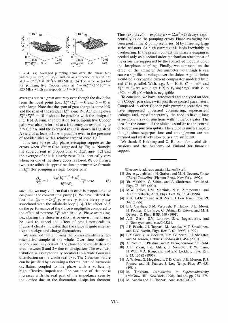
averages out to a great accuracy even though the deviationfrom the ideal point (i.e., Eres
J =EmaxJ � 0 and � � 0) is
quite large. Note that the span of gate charge is some 10%and the span of the residual Eres
J some 1%. Achieving evenEresJ =Emax
J � 10�3 should be possible with the design ofFig. 1(b). A similar calculation for pumping five Cooperpairs was also performed at a frequency corresponding toI � 0:2 nA, and the averaged result is shown in Fig. 4(b).A yield of at least 0.2 nA is possible even in the presenceof nonidealities with a relative error of some 10�6.
It is easy to see why phase averaging suppresses theerrors when Eres
J � 0 as suggested by Fig. 4. Namely,the supercurrent is proportional to Er
JElJ sin’ [12] and
the average of this is clearly zero. It is identically zerowhenever one of the sluice doors is closed. We obtain in atwo-state adiabatic approximation a perturbative formulain Eres
J (for pumping a single Cooper pair)
QP
2e� 1�
2�����������������������������Emax
J �2 � E2C
qEmaxJ EC
EresJ cos’ (6)
such that we may confirm that the error is proportional tocos’ as in the conventional pump [7].We have utilized thefact that QP � �2e d
d’ �, where � is the Berry phaseassociated with the adiabatic loop [13]. The effect of �on the performance of the sluice is negligible compared tothe effect of nonzero Eres
J with fixed ’. Phase averaging,i.e., placing the sluice in a dissipative environment, maybe used to cancel the effect of small nonidealities.Figure 4 clearly indicates that the sluice is quite insensi-tive to background charge fluctuations.
We assumed that choosing the phases evenly is a rep-resentative sample of the whole. Over time scales ofseconds one may consider the phase to be evenly distrib-uted between 0 and 2� due to dissipation. The even dis-tribution is asymptotically identical to a wide Gaussiandistribution on the whole real axis. The Gaussian naturecan be justified by assuming a thermal bath of harmonicoscillators coupled to the phase with a sufficientlyhigh effective impedance. The variance of the phaseincreases with the real part of the impedance seen bythe device due to the fluctuation-dissipation theorem.
Thus hexp��i’�i � exp��ih’i � h�’2i=2� decays expo-nentially as do the pumping errors. Phase averaging hasbeen used in the R-pump scenarios [6] by inserting largeseries resistors. At high currents this leads inevitably tooverheating. In the present context the phase averaging isneeded only as a second order mechanism since most ofthe errors are suppressed by the controlled modulation ofthe Josephson coupling. Finally, we comment on theeffect of the ammeter. An ammeter with high R cancause a significant voltage over the sluice. A good choicewould be a cryogenic current comparator modeled by Land C in parallel. With, e.g., L � 10 H, C � 1 nF, andEmaxJ � EC we would get V�t� � V0 sin�2�ft� with V0 �
e=C� � 50 pV which is negligible.To conclude, we have introduced and analyzed an idea
of a Cooper pair sluice with just three control parameters.Compared to other Cooper pair pumping scenarios, wehave suppressed undesired cotunneling, supercurrentleakage, and, most importantly, the need to have a longerror-prone array of junctions with numerous gates. Theidea for the control of the sluice is similar to the controlof Josephson junction qubits. The sluice is much simpler,though, since superpositions and entanglement are notpursued and relatively slow pulses are sufficient.
We thank F. Hekking and O. Buisson for useful dis-cussions and the Academy of Finland for financialsupport.
*Electronic address: [email protected][1] See, e.g., articles in H. Grabert and M. H. Devoret, Single
Charge Tunneling (Plenum Press, New York, 1992).[2] Yu. Makhlin, G. Schon, and A. Shnirman, Rev. Mod.
Phys. 73, 357 (2001).[3] M.W. Keller, J. M. Martinis, N. M. Zimmerman, and
A. H. Steinbach, Appl. Phys. Lett. 69, 1804 (1996).[4] K. K. Likharev and A. B. Zorin, J. Low Temp. Phys. 59,
347 (1985).[5] L. J. Geerligs, S. M. Verbrugh, P. Hadley, J. E. Mooij,
H. Pothier, P. Lafarge, C. Urbina, D. Esteve, and M. H.Devoret, Z. Phys. B 85, 349 (1991).
[6] A. B. Zorin, S.V. Lotkhov, S. A. Bogoslovsky, andJ. Niemeyer, cond-mat/0105211.
[7] J. P. Pekola, J. J. Toppari, M. Aunola, M.T. Savolainen,and D.V. Averin, Phys. Rev. B 60, R9931 (1999).
[8] L.Y. Gorelik, A. Isacsson, Y. M. Galperin, R. I. Shekhter,and M. Jonson, Nature (London) 411, 454 (2001).
[9] A. Romito, F. Plastina, and R. Fazio, cond-mat/0212414.[10] A. B. Zorin, F.-J. Ahlers, J. Niemeyer, T. Weimann,
H. Wolf, V. A. Krupenin, and S.V. Lotkhov, Phys. Rev.B 53, 13682 (1996).
[11] A. Widom, G. Megaloudis, T. D. Clark, J. E. Mutton, R. J.Prance, and H. Prance, J. Low Temp. Phys. 57, 651(1984).
[12] M. Tinkham, Introduction to Superconductivity(McGraw-Hill, New York, 1996), 2nd ed., pp. 274–278.
[13] M. Aunola and J. J. Toppari, cond-mat/0303176.
00.05
00.005
0.01−2
0
2
x 10− 6
δ/2e E J res/E
J max
(1−
Q P a
ve/1
0e)
00.05
00.005
0.01−5
0
5
x 10− 5
δ/2e E J res/E
J max
(1−
Q P a
ve/2
e)
a) b)
FIG. 4. (a) Averaged pumping error over the phase biasvalues ’ � �=2, �, 3�=2, and 2� as a function of � and Eres
Jat f � Emax
J = �h 10�3�� 300 MHz�. (b) The same as (a) butfor pumping five Cooper pairs at f � 4Emax
J = �h 10�4 �120 MHz which corresponds to I � 0:2 nA.
P H Y S I C A L R E V I E W L E T T E R S week ending24 OCTOBER 2003VOLUME 91, NUMBER 17
177003-4 177003-4
VI/4

Evidence of Cooper pair pumping with combined flux and voltage control
Antti O. Niskanen,1, 2, ∗ Jani M. Kivioja,2 Heikki Seppa,1 and Jukka P. Pekola2
1VTT Information Technology, Microsensing, POB 1207, FIN-02044 VTT, Finland2Low Temperature Laboratory, Helsinki University of Technology, POB 2200, FIN-02015 HUT, Finland
We have experimentally demonstrated pumping of Cooper pairs in a single-island mesoscopicstructure. The island was connected to leads through SQUID (Superconducting Quantum Inter-ference Device) loops. Synchronized flux and voltage signals were applied whereby the Josephsonenergies of the SQUIDs and the gate charge were tuned adiabatically. From the current-voltagecharacteristics one can see that the pumped current increases in 1e steps which is due to quasipar-ticle poisoning on the measurement time scale, but we argue that the transport of charge is due toCooper pairs.
PACS numbers: 74.50.+r, 74.78.Na, 73.23.-bKeywords: Josephson effect, charge pumping
A device that yields a DC current in response to an ACsignal at frequency f according to the relation I = Qfis called a charge pump. In the case of electron pumpsQ = me while for Cooper pair pumps Q = 2me, wherem is an integer denoting the number of charges beingpumped per cycle. Typically pumping electrons in meso-scopic structures requires an array of at least three tun-nel junctions with voltage gates coupled to the islandsin between the junctions. A Cooper pair pump is ob-tained when the tunnel junctions are replaced by Joseph-son junctions. These devices appear at first sight to bevery similar and actually the very same samples mayserve as both Cooper pair and electron pumps depend-ing on whether the device is in the superconducting stateor not. However, major differences exist. Besides thedoubled charge in the superconducting state, the natureof the tunneling processes is very different, too. Elec-trons can tunnel downhill in energy due to the inherentdissipation mechanisms in normal metals with the rele-vant time scale given by the RC time constant, whereR is the tunnel resistance and C the tunnel capacitance.Cooper pairs, on the other hand, try to conserve theirenergy, and in the absence of an electromagnetic envi-ronment, (i.e. zero impedance) only elastic processes arepossible. Their maximum pumping frequency is propor-tional to E2
J/(EC~), where EJ and EC are the Joseph-
son and charging energies, respectively. What is more,superconducting circuits may behave coherently in thequantum-mechanical sense. The first attempt to pumpCooper pairs dates back to over a decade ago1. However,Cooper pair pumps have not been even nearly as accu-rate as single-electron pumps. The best example of thelatter ones is the NIST seven-junction pump2. The mo-tivation behind pumping Cooper pairs is two-fold. Firstof all, Cooper pair pumps are hoped to be able to pumplarger currents than their normal state counterparts whilestill being accurate. This is roughly because increasingE2
J/(EC~) is easier than increasing 1/(RC). Secondly,
the operation of Cooper pair pumps is interesting fromthe point of view of secondary “macroscopic” quantumphenomena and the structures are quite similar to thesuperconducting qubits (see, e.g., Refs. 3,4). Pumping of
electrons using surface acoustic waves is another activefield of study, see, e.g., Ref. 5.
In this work we report on the experimental demonstra-tion of pumping Cooper pairs in a structure nicknamedthe Cooper pair “sluice” introduced and theoretically an-alyzed recently by us, see Ref. 6. The device is particu-larly simple; it has just one superconducting island, likethe single Cooper pair transistor, but the bare Josephsonjunctions are replaced by SQUID loops. The device maybe alternatively viewed as a tunable Cooper pair box, aJosephson charge qubit7. Here the control is achievedvia adiabatically manipulating both the fluxes throughthe two loops and the gate voltage. Ideally the SQUIDsact as tunable Josephson junctions whose coupling en-ergy can be varied between a value close to zero and thesum of the couplings of the individual junctions. First wedescribe the experimental setup and discuss the theoret-ical idea briefly. Then we present measured data of thepumping experiment. We demonstrate that the pumpedcurrent obeys nicely the theoretical predictions. We alsocomment on possible ways of improving the results shouldthe device be used in applications and discuss the signif-icance of the results.
Figure 1 shows an SEM image of the sample used inthe experiments along with a schematic of the measure-ment setup in Fig 1(c). The device was fabricated out ofaluminum using standard e-beam lithography and two-angle shadow evaporation. It consists of a superconduct-ing island that connects to the leads via SQUID loops.These are relatively large (10 µm by 100 µm) in orderto have good inductive coupling but the island and thejunctions are still small such that the charging energy islarge enough (≈1 K) to suppress thermal effects. Thesample was attached to a dilution cryostat with a basetemperature of 20 mK with the RF-lines connected.
Ideally, the pumping of m Cooper pairs is achieved byapplying the three pulses in Fig 2(b) through the atten-uated RF-lines. The upmost signal is applied to the gatewhile the two lower ones represent the currents flowing inthe input coils. Two different versions of the gate pulseare shown, one for pumping “forward” and one for pump-ing “backward”. To understand how the device works,
Submitted for publication 2004. 4 p. APPENDIX VIIcond-mat/0410758
VII/1

2
FIG. 1: (a) Scanning electron micrograph of the sample. Thetwo input coils can be seen on top and bottom, respectively.The gate extends to the far right and the gate capacitance isCg = 0.24 fF based on DC measurements. The current flowsbetween the two leads on the left side. (b) Closeup of theisland. The measured total capacitance of the island is 3.7fF which corresponds to a charging energy of about 1 K forCooper pairs. The maximum EJ per SQUID is estimated tobe around 0.5 K based on the normal state resistance. (c)Schematic illustration of the measurement setup. We usedcommercial room temperature electronics for the current mea-surement and three synchronized arbitrary waveform gener-ators for the control pulse. The external coil for tuning thebackground of the SQUIDs is at 20 mK. The voltage biasinghappens via voltage division through resistive lines. A surfacemount capacitor of 680 pF and an on-chip capacitor on theorder of 10 pF were also used.
it is instructive to look at the Hamiltonian of the device,which reads
H =EC(n − ng)2 − E1
J(Φ1) cos(φ + ϕ/2)
− E2
J(Φ2) cos(ϕ/2 − φ). (1)
Here EC = 2e2/CΣ is the charging energy for Cooperpairs where CΣ is the total capacitance seen from the is-land. Furthermore, Ej
Jwith j = 1, 2 are the (signed)
Josephson energies of the two SQUIDs which can betuned with the external fluxes Φj . For identical junctions
Ej
J= Emax
Jcos(πΦj/Φ0), where Φ0 ≈ 2×10⁻¹⁵ Wb is the
flux quantum and Emax
Jis proportional to the critical cur-
rent IC of the individual junctions via Emax
J= (~/e)IC.
Furthermore, ng = CgVg/2e is the gate charge in 2e units,n is the number operator for Cooper pairs, φ is the phaseon the island and their commutator is [n, φ] = i. The en-vironment couples to the pump through ϕ which is thephase difference over the pump. If the SQUIDs were
- 5 0 0 5 0
- 5 0
0
5 0
0 5 0 1 0 0 1 5 0 2 0 0 2 5 0 3 0 0 3 5 005 0
1 0 01 5 02 0 02 5 03 0 03 5 0
0 1
( a )Q = 0 Q = 0
Q = - 2 e n Q = - 2 e n Q = - 2 e n
C u r r e n t i n c o i l 1 ( m A )C ur r e n
t i n c o
i l 2 (m
A )
f tPulse h
eight (
arb. un
its)
Q = 0
P h a s e o f g a t e s i g n a l ( d e g r e e s )
Phase o
f coil 2
(degre
es)
( c )
( b )( a )
FIG. 2: (a) Contour plot of the measured DC current at con-stant voltage against DC currents in the two input coils. Thetotal variation in the current is around 40 pA at this bias point(150 µV). The arrow line indicates the path along which theflux pulsing is performed in the pumping experiment. Thelines of minimum current along which the arrows are alignedare the lines along which half a flux quantum threads one ofthe two SQUIDs. The slight tilting of the lines is a signa-ture of the inductive cross-coupling. Arranging the pulsingas shown compensates for the cross coupling. (b) Waveformsthat were used in the experiment. The thin almost sinusoidalpulse is the gate signal for pumping in, say, “forward” direc-tion, and the dashed π-shifted signal is for pumping in the“backward” direction. The low level of the gate pulse is zero.The thick lines are the current signals corresponding to thearrowed path in the previous contour plot. (c) Contour plot ofthe measured current at a constant voltage of 250 µV againstthe relative phase differences between the signals with thepumping signal being applied at 2 MHz. The blue circle isthe optimal choice for pumping “forward” while the red circleis the optimal point for pumping “backward”. The ampli-tude was set large (over 400e) and the variation in currentwas 150 pA. This operation point is far from optimal, but westill obtain a clear modulation for calibration purposes.
to have perfectly identical junctions as well as vanishingself-inductance and if the flux control were perfect thenthe effective Josephson couplings could be set to zero.
Figure 2(a) shows a contour plot based on the measure-ment of the current through the device at a constant volt-age against the DC currents in the two input coils. Alongthe lines of minimum current the flux through either ofthe loops is (k +1/2)Φ0, where k is an integer. The mea-surement reveals not only the mutual inductances Mij
between coil i and SQUID j, which were M11 = 30 pH,M12 = 2 pH, M21 = 3 pH and M22 = 50 pH, but alsothe proper offsets at any given time, i.e. the background
VII/2
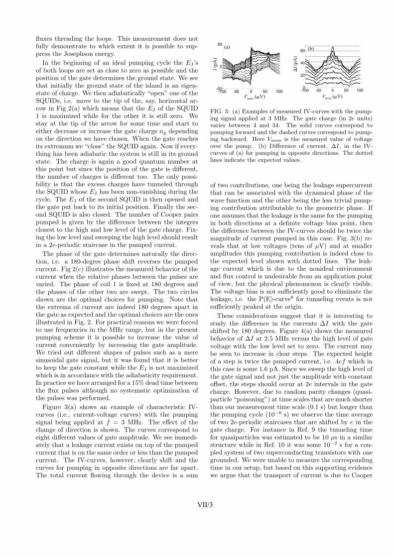
3
fluxes threading the loops. This measurement does notfully demonstrate to which extent it is possible to sup-press the Josephson energy.
In the beginning of an ideal pumping cycle the EJ’sof both loops are set as close to zero as possible and theposition of the gate determines the ground state. We seethat initially the ground state of the island is an eigen-state of charge. We then adiabatically “open” one of theSQUIDs, i.e. move to the tip of the, say, horizontal ar-row in Fig 2(a) which means that the EJ of the SQUID1 is maximized while for the other it is still zero. Westay at the tip of the arrow for some time and start toeither decrease or increase the gate charge ng dependingon the direction we have chosen. When the gate reachesits extremum we “close” the SQUID again. Now if every-thing has been adiabatic the system is still in its groundstate. The charge is again a good quantum number atthis point but since the position of the gate is different,the number of charges is different too. The only possi-bility is that the excess charges have tunneled throughthe SQUID whose EJ has been non-vanishing during thecycle. The EJ of the second SQUID is then opened andthe gate put back to its initial position. Finally the sec-ond SQUID is also closed. The number of Cooper pairspumped is given by the difference between the integersclosest to the high and low level of the gate charge. Fix-ing the low level and sweeping the high level should resultin a 2e-periodic staircase in the pumped current.
The phase of the gate determines naturally the direc-tion, i.e. a 180-degree phase shift reverses the pumpedcurrent. Fig 2(c) illustrates the measured behavior of thecurrent when the relative phases between the pulses arevaried. The phase of coil 1 is fixed at 180 degrees andthe phases of the other two are swept. The two circlesshown are the optimal choices for pumping. Note thatthe extrema of current are indeed 180 degrees apart inthe gate as expected and the optimal choices are the onesillustrated in Fig. 2. For practical reasons we were forcedto use frequencies in the MHz range, but in the presentpumping scheme it is possible to increase the value ofcurrent conveniently by increasing the gate amplitude.We tried out different shapes of pulses such as a meresinusoidal gate signal, but it was found that it is betterto keep the gate constant while the EJ is not maximizedwhich is in accordance with the adiabaticity requirement.In practice we have arranged for a 15% dead time betweenthe flux pulses although no systematic optimization ofthe pulses was performed.
Figure 3(a) shows an example of characteristic IV-curves (i.e., current-voltage curves) with the pumpingsignal being applied at f = 3 MHz. The effect of thechange of direction is shown. The curves correspond toeight different values of gate amplitude. We see immedi-ately that a leakage current exists on top of the pumpedcurrent that is on the same order or less than the pumpedcurrent. The IV-curves, however, clearly shift and thecurves for pumping in opposite directions are far apart.The total current flowing through the device is a sum
- 1 0 0 - 5 0 0 5 0 1 0 0- 5 0
0
5 0
V m e a s ( m V )
I (pA)
( a )
- 1 0 0 - 5 0 0 5 0 1 0 00
2 0
4 0
6 0
V m e a s ( m V )
DI (pA
)
( b )
FIG. 3: (a) Examples of measured IV-curves with the pump-ing signal applied at 3 MHz. The gate charge (in 2e units)varies between 4 and 34. The solid curves correspond topumping forward and the dashed curves correspond to pump-ing backward. Here Vmeas is the measured value of voltageover the pump. (b) Difference of current, ∆I, in the IV-curves of (a) for pumping in opposite directions. The dottedlines indicate the expected values.
of two contributions, one being the leakage supercurrentthat can be associated with the dynamical phase of thewave function and the other being the less trivial pump-ing contribution attributable to the geometric phase. Ifone assumes that the leakage is the same for the pumpingin both directions at a definite voltage bias point, thenthe difference between the IV-curves should be twice themagnitude of current pumped in this case. Fig. 3(b) re-veals that at low voltages (tens of µV) and at smalleramplitudes this pumping contribution is indeed close tothe expected level shown with dotted lines. The leak-age current which is due to the nonideal environmentand flux control is undesirable from an application pointof view, but the physical phenomenon is clearly visible.The voltage bias is not sufficiently good to eliminate theleakage, i.e. the P(E)-curve8 for tunneling events is notsufficiently peaked at the origin.
These considerations suggest that it is interesting tostudy the difference in the currents ∆I with the gateshifted by 180 degrees. Figure 4(a) shows the measuredbehavior of ∆I at 2.5 MHz versus the high level of gatevoltage with the low level set to zero. The current maybe seen to increase in clear steps. The expected heightof a step is twice the pumped current, i.e. 4ef which inthis case is some 1.6 pA. Since we sweep the high level ofthe gate signal and not just the amplitude with constantoffset, the steps should occur at 2e intervals in the gatecharge. However, due to random parity changes (quasi-particle “poisoning”) at time scales that are much shorterthan our measurement time scale (0.1 s) but longer thanthe pumping cycle (10−6 s) we observe the time averageof two 2e-periodic staircases that are shifted by e in thegate charge. For instance in Ref. 9 the tunneling timefor quasiparticles was estimated to be 10 µs in a similarstructure while in Ref. 10 it was some 10−2 s for a cou-pled system of two superconducting transistors with onegrounded. We were unable to measure the correspondingtime in our setup, but based on this supporting evidencewe argue that the transport of current is due to Cooper
VII/3

4
0 1 2 3 4 5012345
0 1 0 2 0 3 0 4 0 5 00
2 0
4 0
6 0
0 2 4 6 8 1 002468
C g V g h i / e
( a )DI
(pA)
( b )
DI (pA
)
1 M H z2 M H z3 M H z4 M H z ( c )
f ( M H z )
DI / (2
C gVghi ) (
MHz)
C g V g h i / e
FIG. 4: (a) Difference ∆I in current of forward and backwardpumping at 2.5 MHz against the high level of the gate signalV hi
g with the low level at zero. The dashed lines are drawnat 2ef intervals. (b) Large gate amplitude behavior of ∆I ata few frequencies. The dashed lines show the expected gatedependece, i.e. their slope is 2ef . The curves are offset forclarity. (c) Fitted slopes to the data of the previous plots upto VgCg/e = 10 are shown by circles. The solid line indicatesthe expected behavior. The voltage bias point was around 10µV in all the above plots.
pairs since the order in which the EJ’s are manipulatedchanges the direction of current. The quasiparticles effec-tively shift the gate charge by e but rarely enough suchthat the pumping is undisturbed on the level of preci-sion of the present measurement. If this interpretationis made then one sees that the obtained results are invery good agreement with theory. Figure 4(b) illustratesthe measured large amplitude behavior of the pumpedcurrent at frequencies between 1 MHz and 4 MHz. Wesee that the current lacks behind the prediction with in-creasing frequency and amplitude. At 1 MHz no clear
bending of the curve is seen up to gate amplitude of 40e,while at 4 MHz the performance starts to degrade after10e. One can observe by looking at Fig. 3(b) that the”bending” is more pronounced at larger bias voltage val-ues (voltage is on the order of 10 µV in Fig. 4) while novisible bending happens up to amplitudes of 68e whenV ≈ 0. Small amplitude behavior in Fig. 4, however,is linear aside from the steps with a slope of 2ef . Fig-ure 4(c) shows the slopes obtained from linear fits to thedata of Fig. 4(a) and the ten first steps of Fig. 4(b). Onesees that the agreement is again good.
The above results prove that the flux and voltagedriven pumping of Cooper pairs is experimentally pos-sible in a single-island device. However, in order to serveas a practical device the leakage current needs to be takencare of as well as the quasiparticle poisoning. The quasi-particles may possibly be handled by either quasiparti-cle “traps” or by BCS gap profile engineering9. As tothe reduction of the leakage, several options exist. Oneoption is the engineering of the electromagnetic environ-ment such that the voltage biasing is good also at fre-quencies on the order of the charging energy. This wouldresult in DC IV-characteristics heavily peaked at zerovoltage with negligible leakage current. Another way tocut down the leakage is to fabricate a longer chain ofjunctions. A multiloop SQUID would possibly improvethe suppression of EJ without increasing the number ofcontrols. Improved RF-engineering would also be of ben-efit in arranging the flux pulses. To conclude, the resultsare encouraging in spite of several nonidealities observedand the pumping of Cooper pairs with flux control looksmuch more attractive than with a mere multiple gatevoltage control.
We thank H. Sipola and S. Franssila for help with themeasurement set-up and device fabrication, and A. An-thore, T. Heikkila, P. Helisto and M. Paalanen for usefuldiscussions. The Academy of Finland and EU IST-FET-SQUBIT2 are acknowledged for financial support.
∗ Electronic address: [email protected] L. J. Geerligs, S. M. Verbrugh, P. Hadley, J. E. Mooij,
H. Pothier, P. Lafarge, C. Urbina, D. Esteve, and M. H.Devoret, Z. Phys. B: Condens. Matter 85, 349 (1991).
2 M. W. Keller, J. M. Martinis, N. M. Zimmerman, and A.H. Steinbach, Appl. Phys. Lett. 69, 1804 (1996).
3 D. Vion, A. Aassime, A. Cottet, P. Joyez, H. Pothier, C.Urbina, D. Esteve, and M. H. Devoret, Science 296, 886(2002).
4 Y.A. Pashkin, T. Yamamoto, O. Astafiev, Y. Nakamura,D.V. Averin, and J.S. Tsai, Nature 421, 823 (2003).
5 J. M. Shilton, V. I. Talyanskii, M. Pepper, D. A. Ritchie,J. E. F. Frost, C. J. B. Ford, C. G. Smith, and G. A. C.
Jones, J. Phys.: Condens. Matter 8, L531 (1996).6 A. O. Niskanen, J. P. Pekola, and H. Seppa, Phys. Rev.
Lett. 91, 177003 (2003).7 Yu. Makhlin, G. Schon, and A. Shnirman, Rev. Mod. Phys.
73, 357 (2001).8 G.-L. Ingold and Yu. V. Nazarov, in Single Charge Tun-
neling, edited by H. Grabert and M.H. Devoret (PlenumPress, New York, 1992), pp. 21–106.
9 J. Aumentado, M. W. Keller, J. M. Martinis, and M. H.Devoret, Phys. Rev. Lett. 92, 066802 (2004).
10 J. Mannik and J. E. Lukens, Phys. Rev. Lett. 92, 057004(2004).
VII/4

Published by
Series title, number and report code of publication
VTT Publications 552 VTT�PUBS�552
Author(s) Niskanen, Antti O. Title Control of Quantum Evolution and Josephson Junction Circuits Abstract Ever since Peter Shor's ground-breaking discovery in 1994 of an algorithm capable of factoring large integers on a quantum-mechanical computer exponentially faster than using any known classical method, research on quantum computing has boomed. Quantum information � a unique mixture of computer science, physics and mathematics � has developed into a new branch of information theory. On the experimental side, physicists from many different disciplines including atomic, solid-state and low-temperature physics, as well as optics, are striving today towards a practical quantum computer. All the candidate quantum bit (qubit) technologies have one thing in common: They rely on the controlled time-evolution of a closed quantum system, a seemingly paradoxical task.
In this Thesis the temporal control of quantum systems is studied. The topics included can be divided into two according to the type of temporal evolution; geometrical or dynamical. Geometrical realization-independent methods for quantum computing are studied first. Then the study is extended into dynamical quantum computing and the so-called Josephson charge-qubit register is considered as a test bench. Finally, a spin-off application of the geometrical evolution of a Josephson junction system is studied, i.e. Cooper pair pumping. A novel Cooper pair pump, the Cooper pair "sluice", is introduced.
The work on quantum computing reported in this Thesis is theoretical while the Cooper pair "sluice" is studied both theoretically and experimentally. Numerical simulations, both sequential and parallel, are used extensively throughout the Thesis. The experiments were carried out under cryogenic mK conditions and the sample fabrication was done using e-beam nanolithography.
Because the execution time of a quantum algorithm is always limited by the inevitable process of decoherence, it is important to utilize any measure available for accelerating quantum computations. It is found that practical quantum algorithms could greatly benefit from classical computer-aided optimization. Moreover, it is found that even a modest demonstrator of a full quantum algorithm using Josephson charge qubits is just barely realizable within present-day coherence times. However, the experimental part of this Thesis shows clear evidence of the functioning of the "sluice". While the worldwide effort of improving the coherence properties of qubits is underway, the "sluice" could well find practical use, e.g., in metrology in the foreseeable future.
Keywords quantum systems, quantum mechanics, quantum computing, quantum algorithms, Cooper pair pumping
Activity unit VTT Information Technology, Tietotie 3, P.O.Box 1207, FIN�02044 VTT, Finland
ISBN Project number 951�38�6420�0 (soft back ed.) 951�38�6421�9 (URL:http://www.inf.vtt.fi/pdf/ )
Date Language Pages Price October 2004 English 46 p. + app. 61 p. C.
Series title and ISSN Sold by VTT Publications 1235�0621 (soft back ed.) 1455�0849 (URL: http://www.vtt.fi/inf/pdf/)
VTT Information Service P.O.Box 2000, FIN�02044 VTT, Finland Phone internat. +358 9 456 4404 Fax +358 9 456 4374

VT
T PU
BL
ICA
TIO
NS 552
Control of Q
uantum E
volution and Josephson Junction Circuits
Antti O
. Niskanen
Tätä julkaisua myy Denna publikation säljs av This publication is available from
VTT TIETOPALVELU VTT INFORMATIONSTJÄNST VTT INFORMATION SERVICEPL 2000 PB 2000 P.O.Box 2000
02044 VTT 02044 VTT FIN–02044 VTT, FinlandPuh. (09) 456 4404 Tel. (09) 456 4404 Phone internat. +358 9 456 4404Faksi (09) 456 4374 Fax (09) 456 4374 Fax +358 9 456 4374
ISBN 951–38–6420–0 (soft back ed.) ISBN 951–38–6421–9 (URL: http://www.vtt.fi/inf/pdf/)ISSN 1235–0621 (soft back ed.) ISSN 1455–0849 (URL: http://www.vtt.fi/inf/pdf/)
ESPOO 2004 VTT PUBLICATIONS 552
Antti O. Niskanen
Control of Quantum Evolution andJosephson Junction Circuits
Ever since Peter Shor's ground-breaking discovery in 1994 of an algorithmcapable of factoring large integers on a quantum-mechanical computerexponentially faster than using any known classical method, research onquantum computing has boomed. Quantum information – a unique mixtureof computer science, physics and mathematics – has developed into a newbranch of information theory. On the experimental side, physicists frommany different disciplines including atomic, solid-state and low-temperature physics, as well as optics, are striving today towards a practicalquantum computer. All the candidate quantum bit technologies have onething in common: They rely on the controlled time-evolution of a closedquantum system, a seemingly paradoxical task. This work investigates thetemporal control of various quantum systems. While the bulk of the workis theoretical, also experimental results are reported. The topics discussedinclude both geometrical and dynamical quantum computing as well asadiabatic charge pumping. Particular attention is paid to Josephsonjunction systems.