katalog techniczny pur en -...
TRANSCRIPT

TECHNICAL CATALOG PANELTECH PW PUR
with PUR corewith PIR core
Version 2018.1.
SANDWICH PANELS
PaNELTECH Sp. z o.o.41-508 Chorzówul. Michałkowicka 24tel. +48 32 245 91 41fax +48 32 245 91 [email protected]
M O D E R N B U I L D I N G


TECHNICAL CATALOG PANELTECH PW PUR
M O D E R N B U I L D I N G
with PUR corewith PIR core
SANDWICH PANELS


CONTENTSINSTRODUCTION .......................................................................................................... 8
SANDWICH PANELS CHARACTERISTICS
THE SCOPE THE OFFER
INSTALLATION RECOMMENDATIONS
TECHNICAL SUPPORT AND OFFER COMPLEXITY
PANEL APPLICATION
PANEL CHARACTERISTICS
WALL SANDWICH PANELS WITH HIDDEN JOINT, TYPE PW PUR-SU
PANEL APPLICATION
PANEL CHARACTERISTICS
ROOF SANDWICH PANELS, TYPE PW PUR-D
PANEL APPLICATION
PANEL CHARACTERISTICS
Draw. S01 - Production scope ...................................................................................... 18
Draw. S03 - The joint between PaNELTECH PW PUR-S 1130 panels .
Draw. S10.1 - Joint between wall panel and ground beam – option I, Panels installed vertically
Draw. S10.3 - Joint between wall panel and ground beam – option III, Panels installed horizontally
Draw. S11.1 - Joint between wall panel and ground beam – option IV, Panels installed vertically
Draw. S11.2 - Joint between wall panel and ground beam – option V, Panels installed vertically
Draw. S12.1 - Joint between wall panel and ground beam – option VI, Panels installed vertically
Draw. S15.1 - Joint between internal wall and floor - Panels installed vertically or horizontally
Draw. S15.2 - Joint between internal wall and floor - Panels installed vertically or horizontally
Draw. S20.1 - Joint between wall panels in the corner - option I, Panels installed vertically or horizontally .........................................................................................
Draw. S20.2 - Joint between wall panels in the corner - option II, Panels installed vertically or horizontally . 29
Draw. S22.1 - Joint between panels and wall, Panels installed vertically or horizontally
Draw. S24.1 - Horizontal Joint between panels, Panels installed vertically
Draw. S24.2 - Vertical joint between panels, Panels installed vertically
Draw. S26.2 - Panel fixing to steel post, edge support, Panels installed horizontally
Draw. S28.2 – Panel fixing to steel post or spandrel beam, intermediate support, Panels installed vertically or horizontally
Draw. S40.1 - Gate opening – the side, One-part opening flashing – option I, Panels installed vertically or horizontally
Draw. S40.2 - Gate opening – the side, One-part opening flashing – option II, Panels installed vertically or horizontally
Draw. S41.1 - Gate opening – the side, Two-part opening flashing – option I, Panels installed vertically or horizontally
SANDWICH PANELS APPLICATION ...................................................................................... 8
................................................................................ 9
.................................................................................................. 9
PACKAGING AND TRANSPORT ......................................................................................... 10
................................................................................. 11
.................................................................. 11
DISCLAMER .............................................................................................................. 11
WALL SANDWICH PANELS WITH VISIBLE JOINT, TYPE PW PUR-S AND PW PIR-S ............................... 12
................................................................................... 12
............................................................................. 12
AND PW PIR-SU ............................ 14
................................................................................... 14
............................................................................. 14
AND PW PIR-D ....................................................... 16
................................................................................... 16
............................................................................. 16...................... 18
........................................... 19
Draw. S04 - Fixing of wall panels PaNELTECH PW PUR-S 1130 ................................................. 19
............. 20
........ 21
Draw. S10.4 - Joint between wall panel and ground beam – option VII, Panels installed horizontaly ........ 22
............ 23
............ 24
........... 25
............ 26
............ 27
28
........................................................................................
..................... 30
.................................... 31
........................................ 32
.......................... 33
............................................................................. 34
............................................................................. 35
............................................................................. 36
............................................................................. 37
Draw. S42.1 - Gate opening – the head, One-part opening flashing – option I, Panels installed vertically or horizontally ............................................................................. 38
DRAWINGS OF CLADDING DETAILS MADE OF PANELTECH SANDWICH PANEL PW PUR-S
5www.paneltech.pl

Draw. S42.2 - Gate opening – the head, One-part opening flashing – option II, Panels installed vertically or horizontally ............................................................................. 39
Draw. S43.1 - Gate opening – the head, Two-part opening flashing – option I, Panels installed vertically or horizontally ............................................................................. 38
Draw. S45.1 - Window installation in steel structure or wall – vertical section, Panels installed vertically or horizontally ............................................................................. 41
Draw. S47.1 - Window installation in sandwich panel – vertical section, Panels installed vertically or horizontally ............................................................................. 42
Draw. S48.1 - Window installation in sandwich panel – horizontal section, Panels installed vertically or horizontally ............................................................................. 43
Draw. S48.2 - Window installation in sandwich panel – horizontal section, Panels installed vertically or horizontally ............................................................................. 43
....................
Draw ...................................................................................... 45
Draw. SU02 - The joint between PaNELTECH PW PUR-SU 1050 panels .......................................... 46
Draw ................................................ 46
Draw .......... 47
................... 48
Draw ...................................................................................... 48
Draw ................................................................................. 49
Draw ................................................................. 50
Draw ...................................... 51
Draw ............................................ 52
Draw. ............................................ 53
Draw ................................................................ 54
Draw............................................................................................. 55
Draw............................................................................................. 56
Draw............................................................................................. 57
Draw............................................................................................. 58
Draw............................................................................................. 59
Draw .............................. 60
Draw ........................ 61
Draw.................................................................................... 62
Draw ................................................................. 63
Draw............................................................................................. 64
Draw...................................................................... 65
66
DRAWINGS OF CLADDING DETAILS MADE OF PANELTECH SANDWICH PANEL PW PUR-SU 45
. SU01 – Production scope
. SU03 – Fixing of wall panels PaNELTECH PW PUR-SU 1050
. SU05 - Drawings of PW PUR-SU joints were shown on respective panel PW PUR-S drawings
DRAWINGS OF ROOF COVER DETAILS MADE OF PaNELTECH SANDWICH PANEL PW PUR-S
. D01 – Production scope
. D02 - Overlap cutting types
. D03 - Suggested placement of the fixings
. D10 - Panel installation on the roof ridge – slope sectional view
. D11.1 - The joint between wall and roof panels, Gutter eaves
D11.3 - The joint between wall and roof panels, Gutter eaves
. D13.1 - The joint between roof panel and wall, Shed roof with eaves – horizontal section of the slope
. D13.2 - The joint between roof panel and wall, Shed roof without eaves – horizontal section of the slope
. D14.1 - The joint between roof panel and top wall, Shed roof with eaves – cross section of the slope
. D14.2 - The joint between roof panel and top wall, Shed roof without eaves – cross section of the slope
. D15.1 - The joint between roof panel and attic wall, Shed roof – horizontal section of the slope
. D15.2 - The joint between roof panel and wall, Cross section of the slope
. D15.3 - The joint between roof panel and attic wall – cross section of the slope
. D15.4 - The joint between roof panel and reinforced concrete wall, Shed roof – horizontal section of the slope
. D18 - Internal gutter – technical solutions
. D20.1 - The joint between roof panel and arc roof ridge skylight, Horizontal section of the slope
. D22 - The joint between roof panel and arc skylight distant from the roof ridge, Horizontal section of the slope
LOAD BEARING TABLES FOR PW PUR-S, PW PUR-SU AND PW PUR-D PANELS ...................................
. D12 - Dilatation joint between roof panels
6 www.paneltech.pl

TABLES
Table no. 1. Packaging of wall sandwich panels PaNELTECH, type PW PUR-S, PW PUR-SU, PW PIR-S and PW PIR-SU ....................................................................................... 10
Table no. 2. Packaging of coldroom sandwich panels PaNELTECH, type PW PUR-CH and PW PIR-CH .... 10
Table no. 3. Packaging of roof sandwich panels PaNELTECH, type PW PUR-D and PW PIR-D ............. 10
Table no. 4. Thickness and weight of PW PUR-S / PW PIR-S panels .......................................... 12
Table no. 5. Insulation and acoustic properties of PW PUR- S / PW PIR-S panels ........................... 13
Table no. 6. Fire classifications for PW PUR-S / PW PIR-S panel ............................................ 13
Table no. 7. Thickness and weight of PW PUR-SU / PW PIR-SU panels ...................................... 14
Table no. 8. Insulation and acoustic properties of PW PUR-SU / PW PIR-SU panels ........................ 15
Table no. 9. Fire classifications for PW PUR-SU / PW PIR-SU panel ......................................... 15
Table no. 10. Thickness and weight of PW PUR-D / PW PIR-D panels ....................................... 16
Table no. 11. Insulation and acoustic properties of PW PUR-D / PW PIR-D panels ........................... 17
Table no. 12. Fire classifications for PW PUR-D / PW PIR-D panel ............................................. 172Table no. 13. Maximal allowable spans for evenly distributed wind characteristic load [kN/m ] for
panel PW PUR-S 40 mm and PW PIR-S 40 mm ..................................................... 662Table no. 14. Maximal allowable spans for evenly distributed wind characteristic load [kN/m ] for
panel PW PUR-S 60 mm and PW PIR-S 60 mm ..................................................... 672Table no. 15. Maximal allowable spans for evenly distributed wind characteristic load [kN/m ] for
panel PW PUR-S 80 mm and PW PIR-S 80 mm ..................................................... 682Table no. 16. Maximal allowable spans for evenly distributed wind characteristic load [kN/m ] for
panel PW PUR-S 100 mm and PW PIR-S 100 mm .................................................. 692Table no. 17. Maximal allowable spans for evenly distributed wind characteristic load [kN/m ] for
panel PW PUR-S 120 mm and PW PIR-S 120 mm .................................................. 702Table no. 18. Maximal allowable spans for evenly distributed wind characteristic load [kN/m ] for
panel PW PUR-SU 60 mm and PW PIR-SU 60 mm ................................................ 712Table no. 19. Maximal allowable spans for evenly distributed wind characteristic load [kN/m ] for
panel PW PUR-SU 80 mm and PW PIR-SU 80 mm ................................................. 722Table no. 20. Maximal allowable spans for evenly distributed wind characteristic load [kN/m ] for
panel PW PUR-SU 100 mm and PW PIR-SU 100 mm ............................................. 732Table no. 21. Maximal allowable spans for evenly distributed wind characteristic load [kN/m ] for
panel PW PUR-SU 120 mm and PW PIR-SU 120 mm ............................................. 742Table no. 22. Maximal allowable spans for evenly distributed characteristic load [kN/m ] for
panel PW PUR-D 40/82 and PW PIR-D 40/82 mm ............................................... 752Table no. 23. Maximal allowable spans for evenly distributed characteristic load [kN/m ] for
panel PW PUR-D 60/102 and PW PIR-D 60/102 mm ............................................. 762Table no. 24. Maximal allowable spans for evenly distributed characteristic load [kN/m ] for
panel PW PUR-D 80/122 and PW PIR-D 80/122 mm ............................................. 772Table no. 25. Maximal allowable spans for evenly distributed characteristic load [kN/m ] for
panel PW PUR-D 90/132 and PW PIR-D 90/132 mm ............................................ 782Table no. 26. Maximal allowable spans for evenly distributed characteristic load [kN/m ] for
panel PW PUR-D 100/142 and PW PIR-D 100/142 mm ........................................... 792Table no. 27. Maximal allowable spans for evenly distributed characteristic load [kN/m ] for
panel PW PUR-D 120/162 and PW PIR-D 120/162 mm .......................................... 802Table no. 28. Maximal allowable spans for evenly distributed characteristic load [kN/m ] for
panel PW PUR-D 160/202 and PW PIR-D 160/202 mm .......................................... 81
7www.paneltech.pl
DisclamerThe author – PaNELTECH Ltd – serves the right to introduce changes in this catalog without prior notice. The catalog is not an offer in the legal meaning.

PaNELTECH Ltd is a company specialized in building services and production of building materials. We have been present on the market of investment and industrial goods since 1989. High quality of our products is a result of modern production technology and application of materials and components supplied by renowned domestic and foreign companies. Thanks to our knowledge, experience and engagement we are able to offer high quality building services and satisfy the changeable needs of our Customers.
We are building our competitive advantage mainly by introducing modern and innovative products and technologies. As a result of this strategy in the past few years we made several important investments, such as purchase and installation of modern machinery park for production of industrial and coldroom doors, new expanded polystyrene (EPS) production line and new EPS and mineral wool sandwich panel production line. However we are most proud of our latest investment in one of the Europe's most modern and innovative polyurethane panels production line. Thanks to this investment we have introduced 3 new products:ź Sandwich panels with PUR core, type PW PUR,ź Sandwich panels with PIR core, type PW PIR,ź Insulation panels in soft facings, type PW PIR SOFT.
We have to underline the fact that the line is equipped in several innovative solutions mainly in the area of quality control. Thanks to them our panels distinguish themselves on the market with their technical parameters, durability and precision.
Sandwich panels can be applied as:ź roofs and roof coveringsź external walls and wall claddingsź walls and ceilings within the external structure of the building.
Sandwich panels PaNELTECH PW PUR and PW PIR are a group of modern composite products, used widely in building industry. Sandwich panels comprises of two steel sheet facings, resistant to corrosion, and an insulation core made of polyurethane foam.
The mail advantages of sandwich panels are:ź high mechanical enduranceź high heat insulation,ź high vapour and air tightness of the joints,ź easy and fast installation,
lower investment cost in comparison with traditional ways of building
In particular sandwich panels can be applied in: ź Industrial buildings, including production facilities and storehouses, ź Commercial buildings and offices,ź Food industry facilities, including coldrooms and freezer rooms,ź Agricultural objectsź Sport halls.
ź
8 www.paneltech.pl
INSTRODUCTION
SANDWICH PANELS APPLICATION

9www.paneltech.pl
Panel facings are made of galvanized steel sheet coated with polyester paint, thickness from 0,4 to 0,6 [mm] made in accordance with the norm PN-EN 10346:2009. The steel we use to produce our panels are delivered by biggest world steel concerns, such as Arcelor Mittal, Voest Alpine or Thyssen Krupp.
The core of the panel can be made of polyurethane foam (PUR) or (PIR) with density of about 340 ± 3 [kg/m ], made in accordance with the norm PN-EN 13165 (including dimensions stability and heat
insulation). A declared heat conductivity value of foam is PUR D = 0,023[W/mxK], PIR D = 0,023[W/mxK].
Technical documentation of the panels was developed in accordance with the norm 14509:2010. Initial type tests were conducted in domestic laboratories, fire tests we made in certified units, such as Building Research Institute, Fire Research Department, notification no. 1488 and Research facility Fires Batizovce, Slovakia, notification no. 1396. On the basis of tests results the producer issued a declaration of conformity with European Norm and marked the product with CE sign (conformity evaluation system 3).
PaNELTECH sandwich panels were also granted a hygienic certificate of National Institute of Hygiene.
Within the range of polyurethane panels we offer following products:ź Wall panels with visible joint, type PW PUR-S and PW PIR-S, available thickness: 40, 60, 80, 100,
120 [mm];ź Wall panels with hidden joint, type PW PUR-SU and PW PIR-SU, available thickness 60, 80, 100,
120 [mm];ź Coldroom panels, type W PUR-CH and PW PIR-CH, available thickness: 120, 160, 180, 200 [mm];ź Rood panels, type PW PUR-D and PW PIR-D, available thickness: 40/82, 60/102, 80/122, 90/132,
100/142, 120/162, 160/202 [mm].
λ λ
SANDWICH PANELS CHARACTERISTICS
THE SCOPE THE OFFER

10 www.paneltech.pl
PACKAGING AND TRANSPORT
For transportation the panels are packed in packaged, that are secured with protective stretch foil. The quantity of panels depending on panel thickness are shown in tables below.
Panel thickness, [mm]
Maximal number of panels in the package [pcs.]*
Panel thickness, [mm]
Maximal number of panels in the package [pcs.]*
120
9
160
7
180
6
200
5
Panel thickness, [mm]
Maximal number of panels in the package [pcs.]*
40/82
18
60/102
14
100/142
8/10
120/162
8
80/122
10/12
90/132
10
40
16
60
18
80
14
100
11
120
9
160/202
6
* in accordance with customer’s clear instruction more panels can be loaded in the package, but it may cause some deformations on the bottom facings of the lower panels in the package.
The packages are loaded on trucks with special forklifts with maximal forks spread of 4 meters. The forks must be secured with special felts in order to avoid scratching of panel surface.
On the building site the panels have to be unloaded with above mentioned forklifts or other suitable lifting devices. In case the panel are shorter than 6m the unloading can be handled with a single forklift. If the panels are longer two forklifts should be used. In case the crane is used proper supports and catches should be applied in order to avoid damages to the panels.
The shipment should be done by trucks adopted to panel transportation. The following conditions must be keptź the width of the loading case shouldn't be at least 2450 [mm],ź free access to the sides of the loading box must be ensured,ź the panels must be secured with belts and spacers to avoid shifting of the packages,ź the belts must be tightened carefully, ź there can be maximum 2 packages in a pile.
Table no.3. Packaging of roof sandwich panels PaNELTECH, type PW PUR-D and PW PIR-D.
Table no.2. Packaging of coldroom sandwich panels PaNELTECH, type PW PUR-CH and PW PIR-CH.
Table no.1. Packaging of wall sandwich panels PaNELTECH, type PW PUR-S, PW PUR-SU, PW PIR-S and PW PIR-SU.
* in accordance with customer’s clear instruction more panels can be loaded in the package, but it may cause some deformations on the bottom facings of the lower panels in the package.
* in accordance with customer’s clear instruction more panels can be loaded in the package, but it may cause some deformations on the bottom facings of the lower panels in the package.

11www.paneltech.pl
INSTALLATION RECOMMENDATIONS
TECHNICAL SUPPORT AND OFFER COMPLEXITY
Installation works should be carried out by trained and experienced employers. The panels should be cut only with special fine-grained sawing machines or steel sheet shears. Any grinders or other devices that could damage the product must be avoided. After the installation the surface of the panel should be cleaned of PU foam and steel file dust.
It is also recommended to remove the protective foil from the surface of the panels up to 14 days after delivery to the building site.
Thanks to our experienced and qualified technical advisors and sale managers we ensure proper assistance and support on every stage of building process.
We also offer high quality services including installation of steel structures and sandwich panels, as well as general execution of industrial and agricultural building facilities (“turn key” investments).
Except for sandwich panels in PUR, PIR, EPS and mineral wool core we offer:ź flashing systems,ź joining and assembly elements,ź PVC and aluminium joinery,ź industrial and coldroom doors,ź gutter systems,ź EPS boards and shapes,ź steel structures,ź Hormann gates and loading systems.
More detailed information can be found on our web-site www.paneltech.pl
All solutions shown in this catalog are just examples and must be discussed with a designer or architect. Paneltech does not bare any responsibility for mistakes arising from wrong interpretation or misuse of the information presented in the catalog.
Additional information, including:ź General Warranty Conditions,ź General Sale Conditions,ź Conditions of panel maintenance and proper preservation of its surface,ź Conditions of panel transportation, loading, unloading and storage,ź Installation instructions,
Can be found on the company's web-site www.paneltech.pl.
DISCLAMER

12 www.paneltech.pl
WALL SANDWICH PANELS WITH VISIBLE JOINT, TYPE PW PUR-S AND PW PIR-S
PANEL APPLICATION
PANEL CHARACTERISTICS
PW PUR-S and PW PIR-S panels are applied as ceilings external walls and internal division walls, installed vertically or horizontally on single- or multi-span structure.
In particular the panels can be applied in industrial buildings, store houses and logistic centres, commercial buildings and offices, food industry facilities, agricultural objects, sport halls.
Dimensions of panel are following:ź standard width: 1130mm (option: 1000 and 1050 [mm])ź available length: from 2 to 15,35 [m]ź available thickness: 40, 60, 80, 100, 120 [mm]
Tables 4, 5 and 6 present chosen PW PUR-S / PW PIR-S panel characteristics.
Table 4. Thickness and weight of PW PUR-S / PW PIR-S panels.
The test of thermal conductivity (symbol) for PU foam was made in accordance with the norm PN-EN 12667. The calculation of thermal transmittance U was done in accordance with PN-EN ISO 6946.
Acoustic properties of the panels were tested in accordance with PN-EN ISO 20140 and PN-EN ISO 354 and classified according to PN-EN ISO 717-1 and PN-EN ISO 11654.
Panel thickness
Panel weight
Foam density
Sealing on the joint
PU gasket
PU gasket
PU gasket
PU gasket
40
60
80
100
120
9,9
10,7
11,5
12,3
13,1
40 ± 3
40 ± 3
40 ± 3
40 ± 3
40 ± 3 PU gasket
13www.paneltech.pl
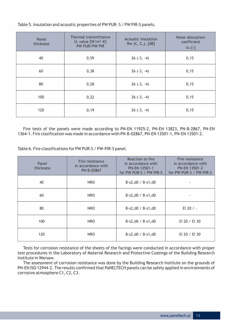
Table 5. Insulation and acoustic properties of PW PUR- S / PW PIR-S panels.
Fire tests of the panels were made according to PN-EN 11925-2, PN-EN 13823, PN-B-2867, PN-EN 1364-1. Fire clasification was made in accordance with PN-B-02867, PN-EN 13501-1, PN-EN 13501-2.
Table 6. Fire classifications for PW PUR-S / PW-PIR-S panel.
Tests for corrosion resistance of the sheets of the facings were conducted in accordance with proper test procedures in the Laboratory of Material Research and Protective Coatings of the Building Research Institute in Warsaw.
The assessment of corrosion resistance was done by the Building Research Institute on the grounds of PN-EN ISO 12944-2. The results confirmed that PaNELTECH panels can be safely applied in environments of corrosive atmosphere C1, C2, C3.
Panel thickness
Thermal transmittance U value [W/m²·K]c PW PUR/PW PIR
Acoustic insulation Rw (C, C ), [dB]tr
Noise absorption coefficient
aw [-]
40
60
80
100
120
26 (-3, -4)
26 (-3, -4)
26 (-3, -4)
26 (-3, -4)
26 (-3, -4)
0,15
0,15
0,15
0,15
0,15
Panel thickness
Fire resistancein accordance with
PN-B-02867
Reaction to firein accordance with
PN-EN 13501-1for PW PUR-S / PW PIR-S
Fire resistancein accordance with
PN-EN 13501-2for PW PUR-S / PW-PIR-S
40
60
80
100
120
NRO
NRO
NRO
NRO
NRO
B-s2,d0 / B-s1,d0
B-s2,d0 / B-s1,d0
B-s2,d0 / B-s1,d0
B-s2,d0 / B-s1,d0
B-s2,d0 / B-s1,d0
-
-
EI 20 / -
EI 20 / EI 30
EI 20 / EI 30
0,59
0,38
0,28
0,22
0,19
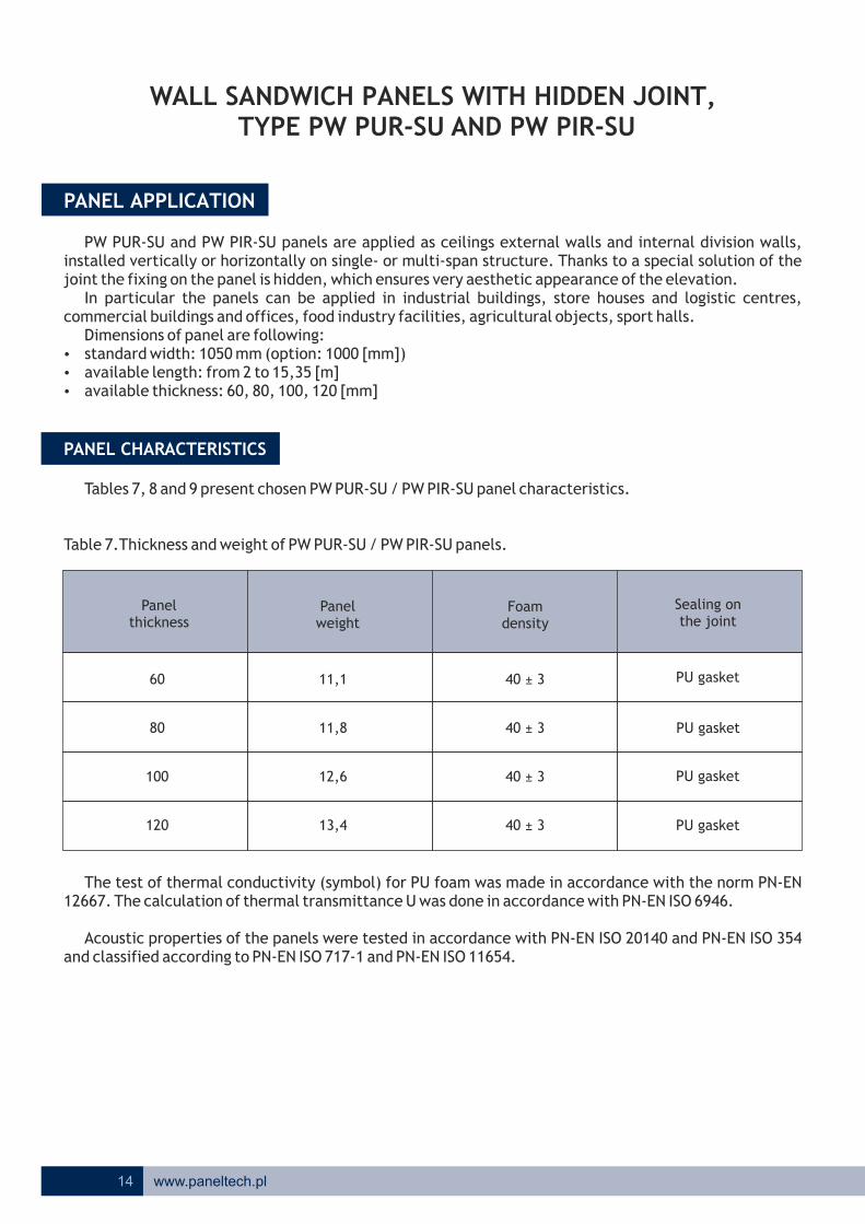
WALL SANDWICH PANELS WITH HIDDEN JOINT, TYPE PW PUR-SU AND PW PIR-SU
PW PUR-SU and PW PIR-SU panels are applied as ceilings external walls and internal division walls, installed vertically or horizontally on single- or multi-span structure. Thanks to a special solution of the joint the fixing on the panel is hidden, which ensures very aesthetic appearance of the elevation.
In particular the panels can be applied in industrial buildings, store houses and logistic centres, commercial buildings and offices, food industry facilities, agricultural objects, sport halls.
Dimensions of panel are following:ź standard width: 1050 mm (option: 1000 [mm])ź available length: from 2 to 15,35 [m]ź available thickness: 60, 80, 100, 120 [mm]
Tables 7, 8 and 9 present chosen PW PUR-SU / PW PIR-SU panel characteristics.
Table 7.Thickness and weight of PW PUR-SU / PW PIR-SU panels.
The test of thermal conductivity (symbol) for PU foam was made in accordance with the norm PN-EN 12667. The calculation of thermal transmittance U was done in accordance with PN-EN ISO 6946.
Acoustic properties of the panels were tested in accordance with PN-EN ISO 20140 and PN-EN ISO 354 and classified according to PN-EN ISO 717-1 and PN-EN ISO 11654.
PANEL APPLICATION
PANEL CHARACTERISTICS
Panel thickness
Panel weight
Foam density
Sealing on the joint
60
80
100
120
11,1
11,8
12,6
13,4
40 ± 3
40 ± 3
40 ± 3
40 ± 3
PU gasket
PU gasket
PU gasket
14 www.paneltech.pl
PU gasket

Table 8. Insulation and acoustic properties of PW PUR-SU / PW PIR-SU panels.
Fire tests of the panels were made according to PN-EN 11925-2, PN-EN 13823, PN-B-2867, PN-EN 1364-1. Fire clasification was made in accordance with PN-B-02867, PN-EN 13501-1, PN-EN 13501-2.
Table 9. Fire classifications for PW PUR-SU / PW PIR-SU panel.
Tests for corrosion resistance of the sheets of the facings were conducted in accordance with proper test procedures in the Laboratory of Material Research and Protective Coatings of the Building Research Institute in Warsaw.
The assessment of corrosion resistance was done by the Building Research Institute on the grounds of PN-EN ISO 12944-2. The results confirmed that PaNELTECH panels can be safely applied in environments of corrosive atmosphere C1, C2, C3.
Panel thickness
Fire resistancein accordance with
PN-B-02867
Reaction to firein accordance with
PN-EN 13501-1for PW PUR-SU / PW PIR-SU
Fire resistancein accordance with
PN-EN 13501-2for PW PUR-SU / PW PIR-SU
60
80
100
120
NRO
NRO
NRO
NRO
B-s2, d0
B-s2, d0
B-s2, d0
B-s2, d0
15www.paneltech.pl
Panel thickness
Thermal transmittance 2U value [W/m ·K]c
PW PUR/PW PIR
Acoustic insulation Rw (C, Ctr), [dB]
Noise absorption coefficient
aw [-]
60
80
100
120
26 (-3, -4)
26 (-3, -4)
26 (-3, -4)
26 (-3, -4)
0,15
0,15
0,15
0,15
-
EI 15 / -
EI 15
EI 15
0,39
0,29
0,23
0,19
16 www.paneltech.pl
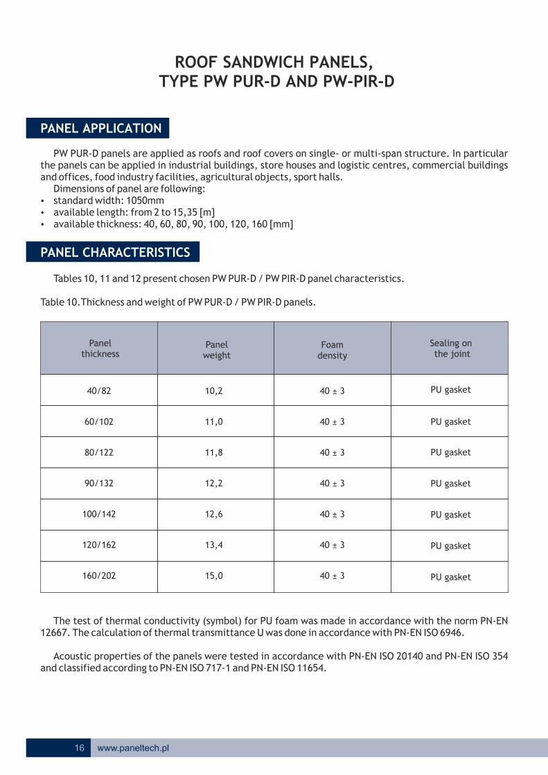
ROOF SANDWICH PANELS, TYPE PW PUR-D AND PW-PIR-D
PW PUR-D panels are applied as roofs and roof covers on single- or multi-span structure. In particular the panels can be applied in industrial buildings, store houses and logistic centres, commercial buildings and offices, food industry facilities, agricultural objects, sport halls.
Dimensions of panel are following:ź standard width: 1050mm ź available length: from 2 to 15,35 [m]ź available thickness: 40, 60, 80, 90, 100, 120, 160 [mm]
Tables 10, 11 and 12 present chosen PW PUR-D / PW PIR-D panel characteristics.
Table 10.Thickness and weight of PW PUR-D / PW PIR-D panels.
The test of thermal conductivity (symbol) for PU foam was made in accordance with the norm PN-EN 12667. The calculation of thermal transmittance U was done in accordance with PN-EN ISO 6946.
Acoustic properties of the panels were tested in accordance with PN-EN ISO 20140 and PN-EN ISO 354 and classified according to PN-EN ISO 717-1 and PN-EN ISO 11654.
PANEL APPLICATION
PANEL CHARACTERISTICS
Panel thickness
Panel weight
Foam density
Sealing on the joint
40/82
60/102
80/122
90/132
100/142
120/162
160/202
10,2
11,0
11,8
12,2
12,6
13,4
15,0
40 ± 3
40 ± 3
40 ± 3
40 ± 3
40 ± 3
40 ± 3
40 ± 3
PU gasket
PU gasket
PU gasket
PU gasket
PU gasket
PU gasket
PU gasket
17www.paneltech.pl
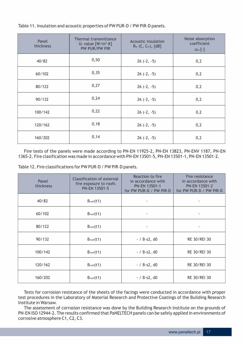
Table 11. Insulation and acoustic properties of PW PUR-D / PW PIR-D panels.
Fire tests of the panels were made according to PN-EN 11925-2, PN-EN 13823, PN-ENV 1187, PN-EN 1365-2. Fire clasification was made in accordance with PN-EN 13501-5, PN-EN 13501-1, PN-EN 13501-2.
Table 12. Fire classifications for PW PUR-D / PW PIR-D panels.
Tests for corrosion resistance of the sheets of the facings were conducted in accordance with proper test procedures in the Laboratory of Material Research and Protective Coatings of the Building Research Institute in Warsaw.
The assessment of corrosion resistance was done by the Building Research Institute on the grounds of PN-EN ISO 12944-2. The results confirmed that PaNELTECH panels can be safely applied in environments of corrosive atmosphere C1, C2, C3.
Panel thickness
Thermal transmittance 2U value [W/m ·K]c
PW PUR/PW PIR
Acoustic insulation Rw (C, Ctr), [dB]
Noise absorption coefficient
aw [-]
Panel thickness
Classification of external fire exposure to roofs
PN-EN 13501-5
Reaction to firein accordance with
PN-EN 13501-1for PW PUR-D / PW PIR-D
Fire resistancein accordance with
PN-EN 13501-2for PW PUR-D / PW PIR-D
40/82
60/102
80/122
90/132
100/142
120/162
160/202
26 (-2, -5)
26 (-2, -5)
26 (-2, -5)
26 (-2, -5)
26 (-2, -5)
26 (-2, -5)
26 (-2, -5)
0,2
0,2
0,2
0,2
0,2
0,2
0,2
40/82
60/102
80/122
90/132
100/142
120/162
160/202
Broof(t1)
B (t1)
B (t1)
B (t1)
B (t1)
B (t1)
roof
roof
roof
roof
roof
Broof(t1)
-
-
-
- / B-s2, d0
- / B-s2, d0
- / B-s2, d0
- / B-s2, d0
-
-
-
RE 30/REI 30
RE 30/REI 30
RE 30/REI 30
RE 30/REI 30
0,50
0,35
0,27
0,24
0,22
0,18
0,14

18 www.paneltech.pl
Wall sandwich panel PaNELTECH PW PUR-S 1130 (visible joint)
Draw. S01
DRAWINGS OF CLADDING DETAILS MADE OF PANELTECH SANDWICH PANEL PW PUR-S*
Production scope
Internal side
External side
1. PU foam core2. Polyurethane gasket, thickness 6mm, applied during production3. Steel sheet facings4. Direction of the arrow on the foil shows external side of panel
Available external facing profiles
Micro-lineal ML
Linear L
Micro-wave MF
Micro-groove MR
Smooth G
Available internal facing profiles
Linear L
Groove R
Smooth G
4
* Drawings refer also to PW PIR-S panels.
19www.paneltech.pl
Draw.
Draw.
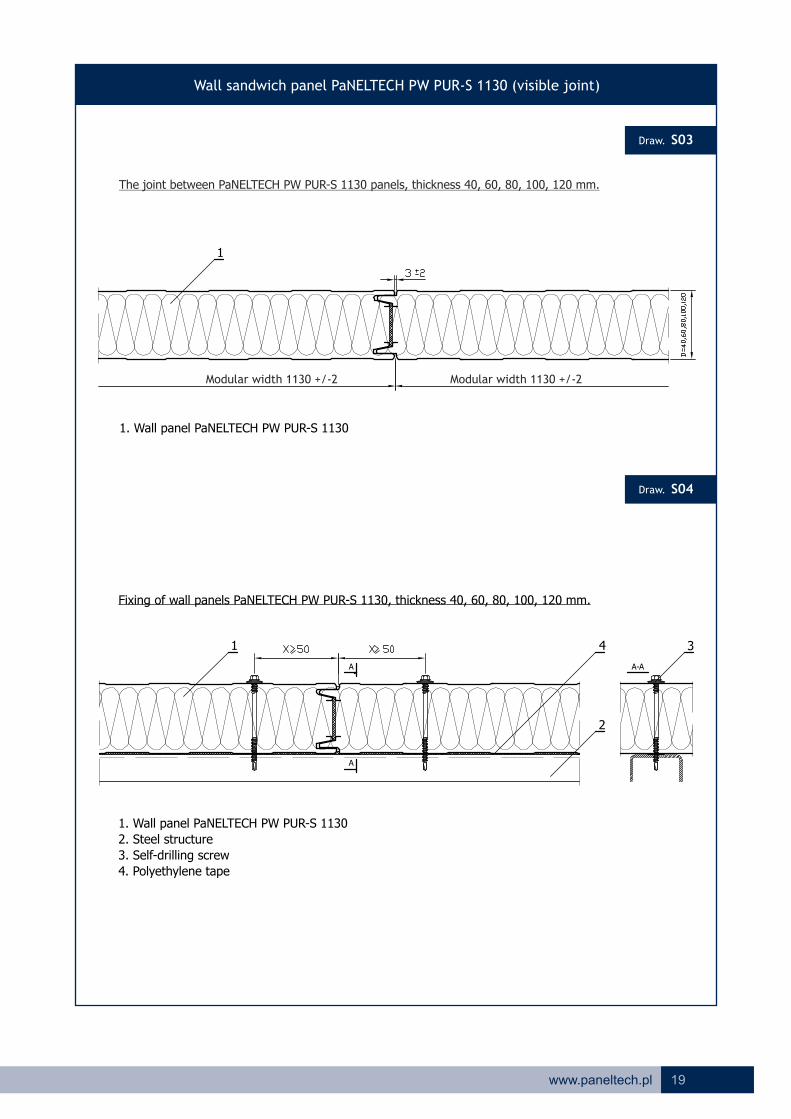
Wall sandwich panel PaNELTECH PW PUR-S 1130 (visible joint)
S03
A
A
A-A
1. Wall panel PaNELTECH PW PUR-S 1130
1. Wall panel PaNELTECH PW PUR-S 1130
2. Steel structure
3. Self-drilling screw
4. Polyethylene tape
1
1
Fixing of wall panels PaNELTECH PW PUR-S 1130, thickness 40, 60, 80, 100, 120 mm.
34
2
S04
The joint between PaNELTECH PW PUR-S 1130 panels, thickness 40, 60, 80, 100, 120 mm.
Modular width 1130 +/-2 Modular width 1130 +/-2
20 www.paneltech.pl
Draw.
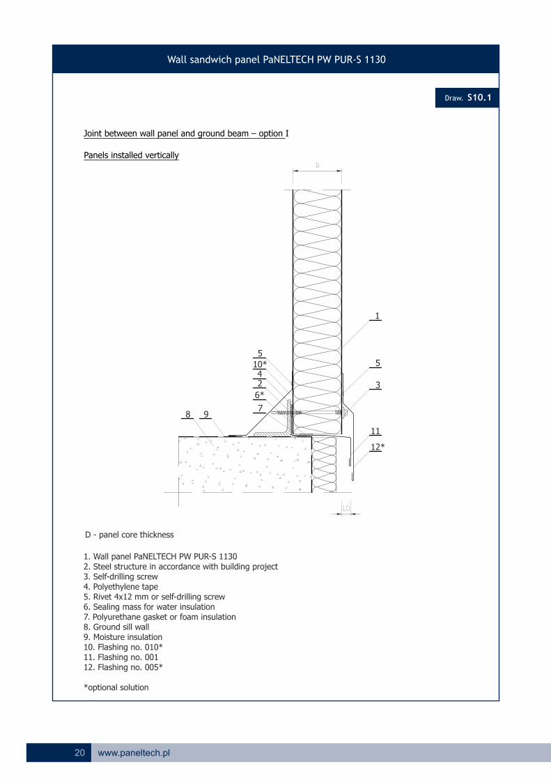
Wall sandwich panel PaNELTECH PW PUR-S 1130
S10.1
Joint between wall panel and ground beam – option I
Panels installed vertically
1. Wall panel PaNELTECH PW PUR-S 11302. Steel structure in accordance with building project3. Self-drilling screw4. Polyethylene tape5. Rivet 4x12 mm or self-drilling screw6. Sealing mass for water insulation7. Polyurethane gasket or foam insulation8. Ground sill wall9. Moisture insulation10. Flashing no. 010*11. Flashing no. 00112. Flashing no. 005*
*optional solution
D - panel core thickness
1
5
12*
3
11
5
10* 4 2
7
6*
8 9

21www.paneltech.pl
Draw.
Wall sandwich panel PaNELTECH PW PUR-S 1130
S10.3
Joint between wall panel and ground beam – option III
Panels installed horizontally
1. Wall panel PaNELTECH PW PUR-S 11302. Steel structure in accordance with building project3. Polyurethane gasket or foam insulation4. Polyethylene tape5. River 4x9 mm6. Moisture insulation7. Ground sill wall8. Flashing no. 0039. Flashing no. 027, 028 or 029
D - panel core thickness
3
1
7 6
2
4
5
8
9

22 www.paneltech.pl
Draw.
Wall sandwich panel PaNELTECH PW PUR-S 1130
S10.4
1
5*
3
9
Joint between wall panel and ground beam – option VII
Panels installed horizontaly
10
3
11*8 2
4
7 6
1. Wall panel PaNELTECH PW PUR-S 11302. Steel structure in accordance with building project3. Rivet 4x12 mm or self-drilling screw4. Polyurethane gasket or foam insulation5. Sealing mass for water insulation6. Moisture insulation7. Ground sill wall8. Polyethylene tape9. Flashing no. 00510. Flashing no. 027, 028 or 02911. Flashing no. 010*
*optional solution
D
D - panel core thickness
23www.paneltech.pl
Draw.
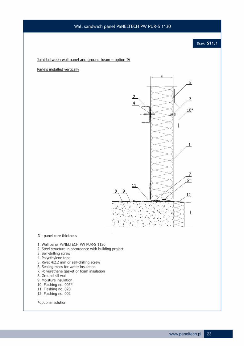
Wall sandwich panel PaNELTECH PW PUR-S 1130
S11.1
Joint between wall panel and ground beam – option IV
Panels installed vertically
1. Wall panel PaNELTECH PW PUR-S 11302. Steel structure in accordance with building project3. Self-drilling screw4. Polyethylene tape5. Rivet 4x12 mm or self-drilling screw6. Sealing mass for water insulation7. Polyurethane gasket or foam insulation8. Ground sill wall9. Moisture insulation10. Flashing no. 005*11. Flashing no. 02012. Flashing no. 002
*optional solution
1
5
6*
7
3
10*
12
2
4
11
98
D
D - panel core thickness

24 www.paneltech.pl
Draw.
Wall sandwich panel PaNELTECH PW PUR-S 1130
S11.2
Joint between wall panel and ground beam – option V
Panels installed vertically
1. Wall panel PaNELTECH PW PUR-S 11302. Steel structure in accordance with building project3. Self-drilling screw4. Polyethylene tape5. Rivet 4x12 mm or self-drilling screw6. Sealing mass for water insulation7. Polyurethane gasket or foam insulation8. Ground sill wall9. Moisture insulation10. Flashing no. 005*11. Flashing no. 01212. Flashing no. 002
*optional solution
1
5
6
3
10*
12
2
4
6
11
8
7
9
A cut in panel facings made on the building siteApplied in objects with higher heat insulation requirements *
D
D - panel core thickness

25www.paneltech.pl
Draw.
Wall sandwich panel PaNELTECH PW PUR-S 1130
S12.1
Joint between wall panel and ground beam – option VI
Panels installed vertically
A cut in panel facings made on the building siteApplied in objects with higher heat insulation requirements *
1. Wall panel PaNELTECH PW PUR-S 11302. Steel structure in accordance with building project or starting list 0753. Self-drilling screw4. Polyethylene tape5. Rivet 4x12 mm or self-drilling screw6. Sealing mass for water insulation7. Polyurethane gasket or foam insulation8. Ground sill wall9. Flashing no. 005*10. Flashing no. 00111. Flashing no. 020
*optional solution
D - panel core thickness
7
5
6
3
9*
2
4
6
1
6
10
2
7 8
11

26 www.paneltech.pl
Draw.
Wall sandwich panel PaNELTECH PW PUR-S 1130
S15.1
Joint between internal wall and floor
Panels installed vertically or horizontally
1
3
57
10
2
4
6*
98
1. Wall panel PaNELTECH PW PUR-S 11302. Steel structure in accordance with building project3. Self-drilling screw4. Polyethylene tape5. Rivet 4x12 mm or self-drilling screw6. Sealing mass for water insulation*7. Polyurethane gasket or foam insulation8. Moisture insulation9. Pin10. Flashing no. 025
*optional solution
D
D - panel core thickness

27www.paneltech.pl
Draw.
Wall sandwich panel PaNELTECH PW PUR-S 1130
S15.2
Joint between internal wall and floor
Panels installed vertically or horizontally
1
3
12*
5
710
11*
2
4
6*
9 8
6
1. Wall panel PaNELTECH PW PUR-S 11302. Steel structure in accordance with building project3. Self-drilling screw4. Polyethylene tape5. Rivet 4x12 mm or self-drilling screw6. Sealing mass for water insulation*7. Polyurethane gasket or foam insulation8. Pin9. Moisture insulation10. Flashing no. 02511. Flashing no. 024*12. Flashing no. 020*
*optional solution
D
D - panel core thickness

28 www.paneltech.pl
Draw.
Wall sandwich panel PaNELTECH PW PUR-S 1130
S20.1
Joint between wall panels in the corner - option I
Panels installed vertically or horizontally
1. Wall panel PaNELTECH PW PUR-S 11302. Steel structure in accordance with building project3. Self-drilling screw4. Polyethylene tape5. Rivet 4x12 mm or self-drilling screw6. Polyurethane gasket or foam insulation7. Sealing mass for water insulation*8. Flashing no. 015
Attention: flashing 015 can be substituted with flashings 017, 018 or 019
D - panel core thickness
1
8
5
3
64 2
7

29www.paneltech.pl
Draw.
Wall sandwich panel PaNELTECH PW PUR-S 1130
S20.2
Joint between wall panels in the corner - option II
Panels installed vertically or horizontally
1. Wall panel PaNELTECH PW PUR-S 11302. Steel structure in accordance with building project3. Self-drilling screw4. Polyethylene tape5. Rivet 4x12 mm or self-drilling screw6. Polyurethane gasket or foam insulation7. Sealing mass for water insulation8. Flashing no. 017
Attention: flashing 017 can be substituted with flashings 015, 018 or 019
D - panel core thickness
7
8
4
5
6
2
1
3

30 www.paneltech.pl
Draw.
Wall sandwich panel PaNELTECH PW PUR-S 1130
S22.1
1
9
11 35
610 4
8 7
Joint between panels and wall
Panels installed vertically or horizontally
2
1. Wall panel PaNELTECH PW PUR-S 11302. Steel and concrete structure component in accordance with building project3. Self-drilling screw4. Polyethylene tape5. Rivet 4x12 mm or self-drilling screw6. Polyurethane gasket or foam insulation7. Pin8. Sealing mass for water insulation9. Wall10. Flashing no. 02011. Flashing no. 026
D
D - panel core thickness

31www.paneltech.pl
Draw.
Wall sandwich panel PaNELTECH PW PUR-S 1130
S24.1
Horizontal Joint between panels
Panels installed vertically
1
2
6*
7
2
43
5
4
1. Wall panel PaNELTECH PW PUR-S 11302. Steel and concrete structure component in accordance with building project3. Self-drilling screw4. Polyethylene tape5. Polyurethane gasket or foam insulation6. Sealing mass for water insulation*7. Flashing no. 001 or 002
*optional solution

32 www.paneltech.pl
Draw.
Wall sandwich panel PaNELTECH PW PUR-S 1130
S24.2
Vertical joint between panels
Panels installed vertically
1
5
8
2
7
2
6
4
4
3
9
1. Wall panel PaNELTECH PW PUR-S 11302. Steel structure component in accordance with building project3. Self-drilling screw4. Polyethylene tape5. Rivet 4x12 mm6. Polyurethane gasket or foam insulation7. Sealing mass for water insulation8. Flashing no. 0279. Flashing no. 002

33www.paneltech.pl
Draw.
Wall sandwich panel PaNELTECH PW PUR-S 1130
S26.2
Panel fixing to steel post, edge support
Panels installed horizontally
1. Wall panel PaNELTECH PW PUR-S 11302. Steel structure component in accordance with building project3. Self-drilling screw4. Polyethylene tape5. Rivet 4x12 mm or self-drilling screw6. Polyurethane gasket or foam insulation7. Sealing mass for water insulation8. Flashing no. 027
Attention: flashing 027 can be substituted with flashings 028 or 029
15386
2
4
7
>20 >20
min 10
34 www.paneltech.pl
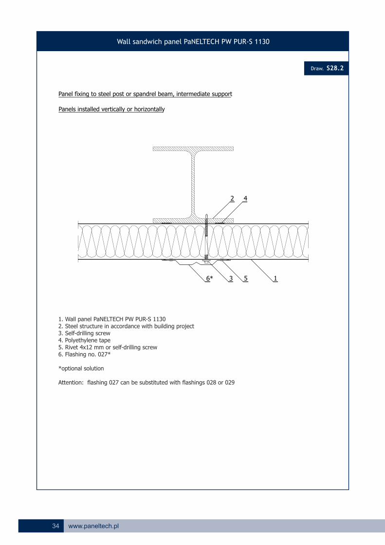
Wall sandwich panel PaNELTECH PW PUR-S 1130
S28.2
42
1536*
Panel fixing to steel post or spandrel beam, intermediate support
Panels installed vertically or horizontally
1. Wall panel PaNELTECH PW PUR-S 11302. Steel structure in accordance with building project3. Self-drilling screw4. Polyethylene tape5. Rivet 4x12 mm or self-drilling screw6. Flashing no. 027*
*optional solution
Attention: flashing 027 can be substituted with flashings 028 or 029
Draw.

35www.paneltech.pl
Wall sandwich panel PaNELTECH PW PUR-S 1130
S40.1
13
Gate opening – the side
One-part opening flashing – option I
Panels installed vertically or horizontally
6
2
4
5
8
7
1. Wall panel PaNELTECH PW PUR-S 11302. Steel structure in accordance with building project3. Self-drilling screw4. Polyethylene tape5. Rivet 4x12 mm or self-drilling screw6. Gate panel7. Flashing 025
Draw.
D
D - panel core thickness

36 www.paneltech.pl
Wall sandwich panel PaNELTECH PW PUR-S 1130
S40.2
Gate opening – the side
One-part opening flashing – option II
Panels installed vertically or horizontally
1. Wall panel PaNELTECH PW PUR-S 11302. Steel structure in accordance with building project3. Self-drilling screw4. Polyethylene tape5. Rivet 4x12 mm or self-drilling screw6. Sectional or rolling gate guide7. Gate panel8. Flashing 036
Attention: flashing 036 can be substituted with flashings 037 or 039
Draw.
13
2
4
5
8
D
D - panel core thickness
6

37www.paneltech.pl
Wall sandwich panel PaNELTECH PW PUR-S 1130
S41.1
13
Attention: flashing 015 can be substituted with flashings 016, 047 or 049
Gate opening – the side
Two-part opening flashing – option I
Panels installed vertically or horizontally
6
2
4
5
9
8
5
7
1. Wall panel PaNELTECH PW PUR-S 11302. Steel structure in accordance with building project3. Self-drilling screw4. Polyethylene tape5. Rivet 4x12 mm or self-drilling screw6. Sectional or rolling gate guide7. Gate panel8. Flashing 0469. Flashing 015
Draw.
D
D - panel core thickness

38 www.paneltech.pl
Wall sandwich panel PaNELTECH PW PUR-S 1130
S42.1
Gate opening – the head
One-part opening flashing – option I
Panels installed vertically or horizontally
4
6
1
2
56
8
7
6
3
910
1. Wall panel PaNELTECH PW PUR-S 11302. Steel structure in accordance with building project3. Self-drilling screw4. Polyethylene tape5. Rivet 4x12 mm or self-drilling screw6. Sealing mass for water insulation7. Sectional gate guide8. Gate panel9. Flashing 02510. Flashing 005
Draw.
D
D - panel core thickness

39www.paneltech.pl
Wall sandwich panel PaNELTECH PW PUR-S 1130
S42.2
Gate opening – the head
One-part opening flashing – option II
Panels installed vertically or horizontally
4
6
1
2
56
8
7
6
3
910
1. Wall panel PaNELTECH PW PUR-S 11302. Steel structure in accordance with building project3. Self-drilling screw4. Polyethylene tape5. Rivet 4x12 mm or self-drilling screw6. Sealing mass for water insulation7. Sectional gate guide8. Gate panel9. Flashing 03610. Flashing 005
Draw.
D
D - panel core thickness

40 www.paneltech.pl
Wall sandwich panel PaNELTECH PW PUR-S 1130
S43.1
Gate opening – the head
Two-part opening flashing – option I
Panels installed vertically or horizontally
4
1
2
56
8
7
6
3
11 5910 6
1. Wall panel PaNELTECH PW PUR-S 11302. Steel structure in accordance with building project3. Self-drilling screw4. Polyethylene tape5. Rivet 4x12 mm or Sealing mass for water insulation6. self-drilling screw7. Sectional or rolling gate guide8. Gate panel9. Flashing 04610. Flashing 015 or 01611. Flashing 005
Draw.
D
D - panel core thickness

Draw.
Wall sandwich panel PaNELTECH PW PUR-S 1130
S45.1
10
3
2
9
4
Window installation in steel structure or wall – vertical section
Panels installed vertically or horizontally
1
8
5
5
6
7
11
11
3
1. Wall panel PaNELTECH PW PUR-S 11302. Steel structure in accordance with building project3. Self-drilling screw4. Polyethylene tape5. Rivet 4x12 mm or self-drilling screw6. Foam insulation7. Aluminium or PVC window8. Flashing 0519. Flashing 05210. Flashing 05311. Flashing 020
41www.paneltech.pl
42 www.paneltech.pl
Draw.
Wall sandwich panel PaNELTECH PW PUR-S 1130
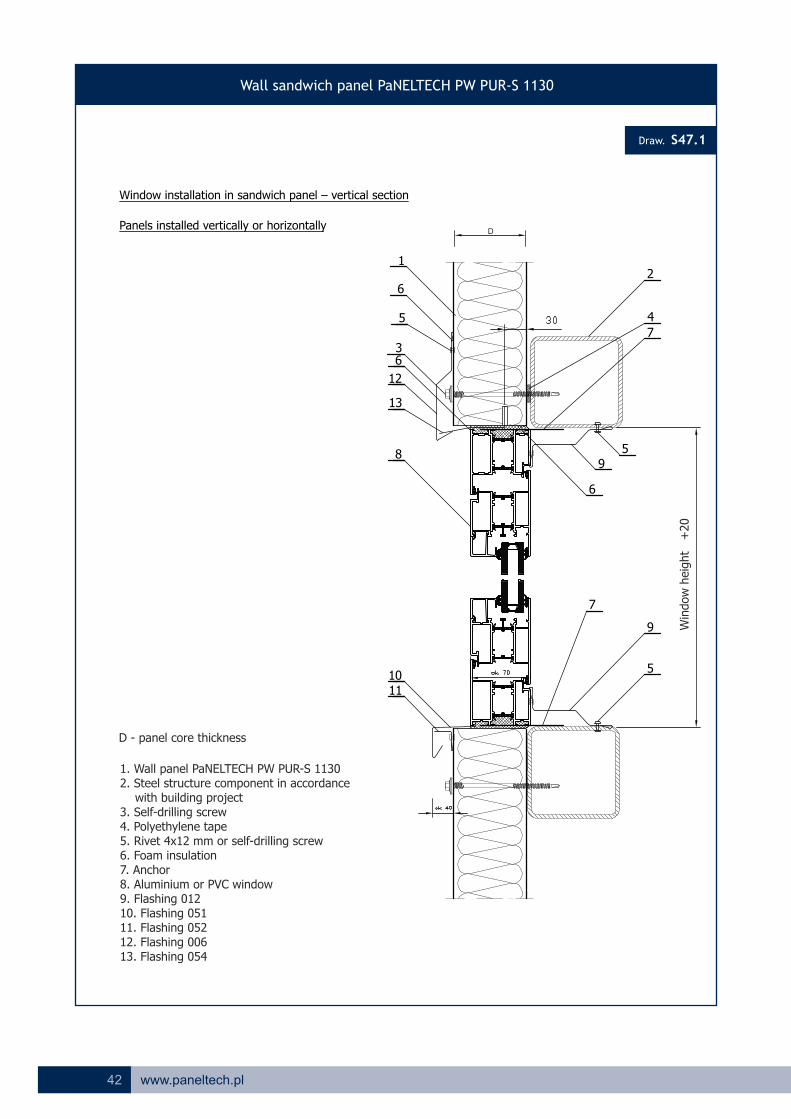
S47.1
Window installation in sandwich panel – vertical section
Panels installed vertically or horizontally
13
12
3
6
8
2
1011
6
6
4
9
5
5
5
1
7
7
9
1. Wall panel PaNELTECH PW PUR-S 11302. Steel structure component in accordance with building project3. Self-drilling screw4. Polyethylene tape5. Rivet 4x12 mm or self-drilling screw6. Foam insulation7. Anchor8. Aluminium or PVC window9. Flashing 01210. Flashing 05111. Flashing 05212. Flashing 00613. Flashing 054
Win
dow
heig
ht
+
20
D
D - panel core thickness

43www.paneltech.pl
Draw.
Wall sandwich panel PaNELTECH PW PUR-S 1130
S48.1
Window installation in sandwich panel – horizontal section
Panels installed vertically or horizontally
56
4
2
11
8
External side
Internal side
5
Option I Option II
5 7123
6
5
10
9 9 1
Window width +20
1. Wall panel PaNELTECH PW PUR-S 11302. Steel structure in accordance with building project3. Self-drilling screw4. Polyethylene tape5. Rivet 4x12 mm or self-drilling screw6. Foam insulation7. Aluminium or PVC window8. Anchor9. Sealing mass for water insulation10. Flashing 01211. Flashing 02612. Flashing 056
D
D - panel core thickness

44 www.paneltech.pl
Draw.
Wall sandwich panel PaNELTECH PW PUR-S 1130
S48.2
12
56
4
2
11
8
Window installation in sandwich panel – horizontal section
Panels installed vertically or horizontally
3 5 7
6
5
10
199
External side
Internal side
Option I Option II
Window width +20
1. Wall panel PaNELTECH PW PUR-S 11302. Steel structure in accordance with building project3. Self-drilling screw4. Polyethylene tape5. Rivet 4x12 mm or self-drilling screw6. Foam insulation7. Aluminium or PVC window8. Anchor9. Sealing mass for water insulation10. Flashing 05811. Flashing 02612. Flashing 055
D
D - panel core thickness

45www.paneltech.pl
Draw.
Wall sandwich panel PaNELTECH PW PUR-SU 1050 (hidden joint)
SU01
DRAWINGS OF CLADDING DETAILS MADE OF PANELTECH SANDWICH PANEL PW PUR-SU*
12
Production scope
3
Available internal facing profiles
Linear L
Groove R
Smooth G
Available external facing profiles
Micro-lineal ML
Linear L
Micro-wave MF
Micro-groove MR
Smooth G
External side
Internal side
1. PU foam core2. Polyurethane gasket, thickness 6mm, applied during production3. Steel sheet facings
24
19
* Drawings refer also to PW PIR-SU panels.
D=
60
,80
,10
0,1
20

46 www.paneltech.pl
Draw.
Draw.
Wall sandwich panel PaNELTECH PW PUR-SU 1050 (hidden joint)
SU02
12
A-A
3
4
1. Wall panel PaNELTECH PW PUR-SU 1050
The joint between PaNELTECH PW PUR-SU 1050 panels, thickness 60, 80, 100, 120 mm.
Fixing of wall panels PaNELTECH PW PUR-SU 1050, thickness 60, 80, 100, 120 mm.
12 A
A
5
6
6
SU03
Modular width 1050 +/-2 Modular width 1500 +/-2
1. Wall panel PaNELTECH PW PUR-SU 10502. Polyurethane gasket applied during production3. Self-drilling screw4. Polyethylene tape5. Steel structure in accordance with building project6. SU washer (flashing 070)
D=
60
,80
,10
0,1
20
D=
60
,80
,10
0,1
20
47www.paneltech.pl
Draw.
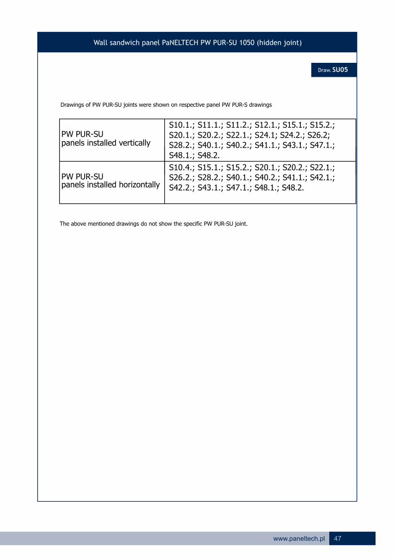
Wall sandwich panel PaNELTECH PW PUR-SU 1050 (hidden joint)
SU05
Drawings of PW PUR-SU joints were shown on respective panel PW PUR-S drawings
panels installed verticallyPW PUR-SU
S10.1.; S11.1.; S11.2.; S12.1.; S15.1.; S15.2.;
S20.1.; S20.2.; S22.1.; S24.1; S24.2.; S26.2;S28.2.; S40.1.; S40.2.; S41.1.; S43.1.; S47.1.;
S48.1.; S48.2.
panels installed horizontallyPW PUR-SU
S10.4.; S15.1.; S15.2.; S20.1.; S20.2.; S22.1.;S26.2.; S28.2.; S40.1.; S40.2.; S41.1.; S42.1.;
S42.2.; S43.1.; S47.1.; S48.1.; S48.2.
The above mentioned drawings do not show the specific PW PUR-SU joint.
48 www.paneltech.pl
Draw.
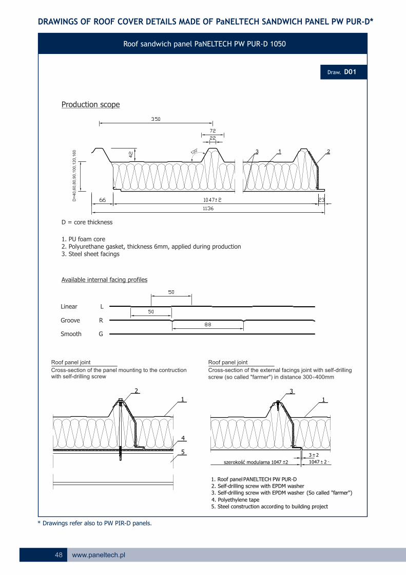
Roof sandwich panel PaNELTECH PW PUR-D 1050
D01
DRAWINGS OF ROOF COVER DETAILS MADE OF PaNELTECH SANDWICH PANEL PW PUR-D*
Production scope
D = core thickness
1. PU foam core2. Polyurethane gasket, thickness 6mm, applied during production3. Steel sheet facings
Available internal facing profiles
Linear L
Groove R
Smooth G
* Drawings refer also to PW PIR-D panels.
Roof panel joint
Cross-section of the panel mounting to the contructionwith self-drilling screw
Roof panel joint
Cross-section of the external facings joint with self-drilling screw (so called "farmer") in distance 300¸400mm
szerokość modularna 1047 2 1047 2
2
1
4
5
3
1
1. Roof panelPANELTECH PW PUR-D
2. Self-drilling screw with EPDM washer
3. (So called "farmer")Self-drilling screw with EPDM washer
4. Polyethylene tape
5. Steel construction according to building project
3 2
o
120
D=
40
,60
,80
,90
,10
0,1
20
,16
0

49www.paneltech.pl
Draw.
Roof sandwich panel PaNELTECH PW PUR-D 1050
D02
Overlap cutting types
RIGHT OVERLAP CUT – PP LEFT OVERLAPP CUT – PL
overlap overlap
panel installation starting from right side panel installation starting from the left side
view from the gutter
Overlap cutting dimensions
L - panel length
P – overlap cut
P = 0mm – no overlap cut
P = 50mm – overlap cut by the eaves (draw. D11.1 and D11.2)
P = 200mm – overlap cut by dilatation joint between panels (draw. D12)
P = 250mm – maximal overlap cut
50 www.paneltech.pl
Draw.
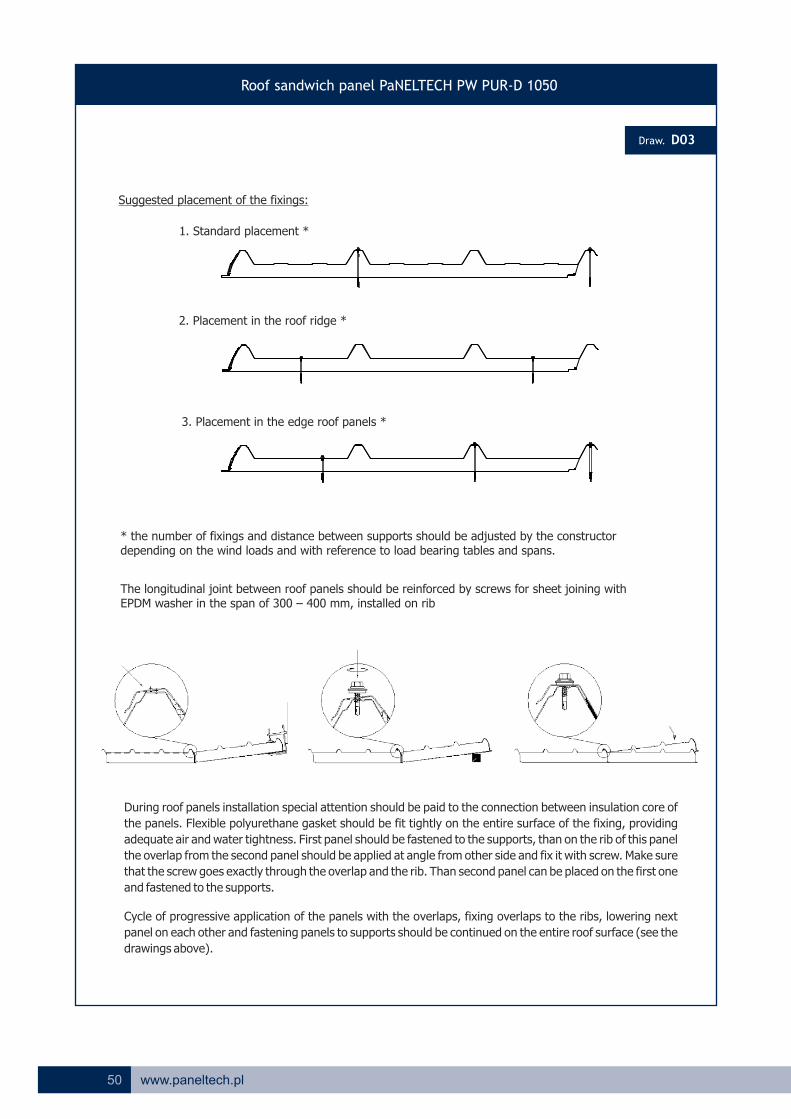
Roof sandwich panel PaNELTECH PW PUR-D 1050
D03
Suggested placement of the fixings:
1. Standard placement *
2. Placement in the roof ridge *
3. Placement in the edge roof panels *
* the number of fixings and distance between supports should be adjusted by the constructor depending on the wind loads and with reference to load bearing tables and spans.
The longitudinal joint between roof panels should be reinforced by screws for sheet joining with EPDM washer in the span of 300 – 400 mm, installed on rib
During roof panels installation special attention should be paid to the connection between insulation core of
the panels. Flexible polyurethane gasket should be fit tightly on the entire surface of the fixing, providing
adequate air and water tightness. First panel should be fastened to the supports, than on the rib of this panel
the overlap from the second panel should be applied at angle from other side and fix it with screw. Make sure
that the screw goes exactly through the overlap and the rib. Than second panel can be placed on the first one
and fastened to the supports.
Cycle of progressive application of the panels with the overlaps, fixing overlaps to the ribs, lowering next
panel on each other and fastening panels to supports should be continued on the entire roof surface (see the
drawings above).

51www.paneltech.pl
Draw.
Roof sandwich panel PaNELTECH PW PUR-D 1050
D10
1
2
1210 85 9*7
11 6
3
5
Panel installation on the roof ridge – slope sectional view
9*
D – panel core thickness
1. Roof panel PaNELTECH PW PUR-D 10502. Steel structure in accordance with building project3. Self-drilling screw4. Polyethylene tape5. Rivet 4x12 mm6. PU foam7. PU gasket UD 428. Self-drilling screw or tight rivet 4x12 mm9. Sealing mass for water insulation, recommended by low roof slope*10. Flashing no. 10111. Flashing no. 10312. Flashing no. 102
*optional solution

52 www.paneltech.pl
Draw.
Roof sandwich panel PaNELTECH PW PUR-D 1050
D11.1
The joint between wall and roof panels
Gutter eaves - option I
139*8*
2
7 4576
10 11*
12
1. Roof panel PaNELTECH PW PUR-D 10502. Wall panel PaNELTECH 3. Self-drilling screw4. Rivet 4x12 mm or self-drilling screw5. Installation PU foam6. Flashing no. 1307. Flashing no. 0208. Flashing no. 109*9. Flashing no. 111*10. Gutter system11. A cut made in the panel facing made to improve thermal insulation *12. Flashing no. 110
*optional solution

53www.paneltech.pl
Draw.
Roof sandwich panel PaNELTECH PW PUR-D 1050
D11.3
The joint between wall and roof panelsGutter eaves - option II
1. Roof panel PaNELTECH PW PUR-D 10502. Wall panel PaNELTECH 3. Self-drilling screw4. Rivet 4x12 mm or self-drilling screw5. Installation PU foam6. Flashing no. 1307. Flashing no. 0208. Roof end cap Z429. Flashing no. 111*10. Gutter system11. A cut made in the panel facing made to improve thermal insulation *12. Flashing no. 110
*optional solution
139*
2
7 4576
10 11*
8
Roof end cap Z42
12
54 www.paneltech.pl
Draw.
Roof sandwich panel PaNELTECH PW PUR-D 1050
D12
11 6 3 6
2
5
4
7
Dilatation joint between roof panels - cross-section along the slope
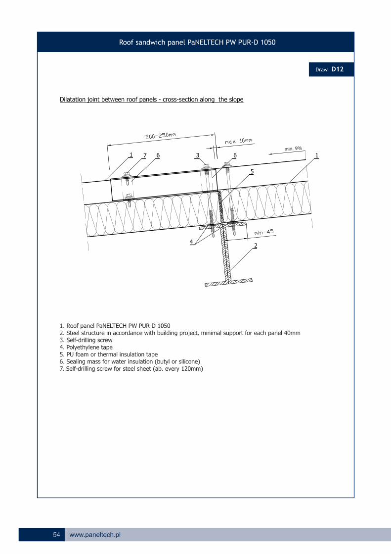
1. Roof panel PaNELTECH PW PUR-D 10502. Steel structure in accordance with building project, minimal support for each panel 40mm3. Self-drilling screw4. Polyethylene tape5. PU foam or thermal insulation tape6. Sealing mass for water insulation (butyl or silicone)7. Self-drilling screw for steel sheet (ab. every 120mm)
min. 9%

55www.paneltech.pl
Roof sandwich panel PaNELTECH PW PUR-D 1050
D13.1
13 8 1113* 710
12
6
12
2
9
4
5
The joint between roof panel and wall
Shed roof with eaves – horizontal section of the slope
14*
13*
D – panel core thickness
5
1. Roof panel PaNELTECH PW PUR-D 10502. Steel structure in accordance with building project3. Self-drilling screw4. Polyethylene tape5. Rivet 4x12mm6. PU foam7. PU gasket UD428. Self-drilling screw for steel sheet9. Wall panel PaNELTECH10. Flashing 10211. Flashing 10612. Flashing 02013. Sealing mass for water insulation, recommended by low roof slope*14. A cut made in the panel facing made to improve thermal insulation *
*optional solution
Draw.

56 www.paneltech.pl
Draw.
Roof sandwich panel PaNELTECH PW PUR-D 1050
D13.2
13 8 1113* 710
6
12
28
9
4
5
The joint between roof panel and wall
Shed roof without eaves – horizontal section of the slope
14*
13*
D – panel core thickness
5
1. Roof panel PaNELTECH PW PUR-D 10502. Steel structure in accordance with building project3. Self-drilling screw4. Polyethylene tape5. Rivet 4x12mm6. PU foam7. PU gasket UD428. Self-drilling screw for steel sheet9. Wall panel PaNELTECH10. Flashing 10211. Flashing 10412. Flashing 02013. Sealing mass for water insulation, recommended by low roof slope*14. A cut made in the panel facing made to improve thermal insulation *
*optional solution
57www.paneltech.pl
Draw.
Roof sandwich panel PaNELTECH PW PUR-D 1050
D14.1
1
27
10
599
3 8
6
4
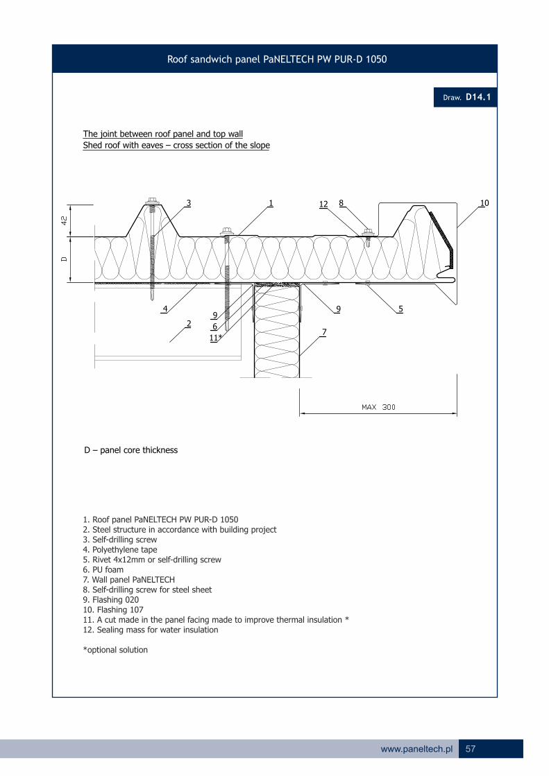
The joint between roof panel and top wall
Shed roof with eaves – cross section of the slope
D – panel core thickness
11*
1. Roof panel PaNELTECH PW PUR-D 10502. Steel structure in accordance with building project3. Self-drilling screw4. Polyethylene tape5. Rivet 4x12mm or self-drilling screw6. PU foam7. Wall panel PaNELTECH8. Self-drilling screw for steel sheet9. Flashing 02010. Flashing 10711. A cut made in the panel facing made to improve thermal insulation *12. Sealing mass for water insulation
*optional solution
12

58 www.paneltech.pl
Draw.
Roof sandwich panel PaNELTECH PW PUR-D 1050
D14.2
1
3
5
The joint between roof panel and top wall
Shed roof without eaves – cross section of the slope
2
46
7*
8
1. Roof panel PaNELTECH PW PUR-D 10502. Wall panel PaNELTECH PW PUR-S 11303. Flashing 0204. Flashing 1055. Rivet 4x12mm or self-drilling screw6. Sealing mass for water insulation7. A cut made in the panel facing made to improve thermal insulation *8. PU foam
*optional solution
59www.paneltech.pl
Draw.
Roof sandwich panel PaNELTECH PW PUR-D 1050
D15.1
9
11
8
1 8 5 13
3
14* 7
10
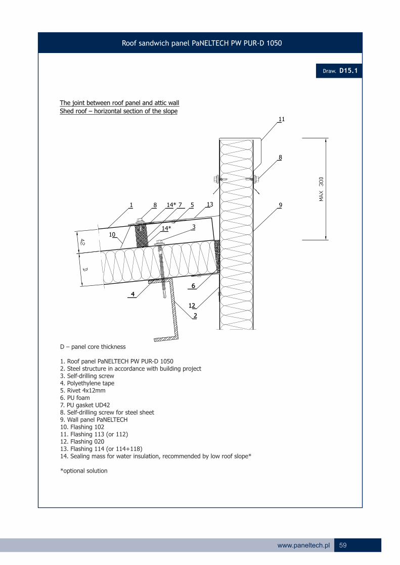
The joint between roof panel and attic wall
Shed roof – horizontal section of the slope
14*
D – panel core thickness
1. Roof panel PaNELTECH PW PUR-D 10502. Steel structure in accordance with building project3. Self-drilling screw4. Polyethylene tape5. Rivet 4x12mm6. PU foam7. PU gasket UD428. Self-drilling screw for steel sheet9. Wall panel PaNELTECH10. Flashing 10211. Flashing 113 (or 112)12. Flashing 02013. Flashing 114 (or 114+118)14. Sealing mass for water insulation, recommended by low roof slope*
*optional solution
60 www.paneltech.pl
Draw.
Roof sandwich panel PaNELTECH PW PUR-D 1050
D15.2
1
3
7
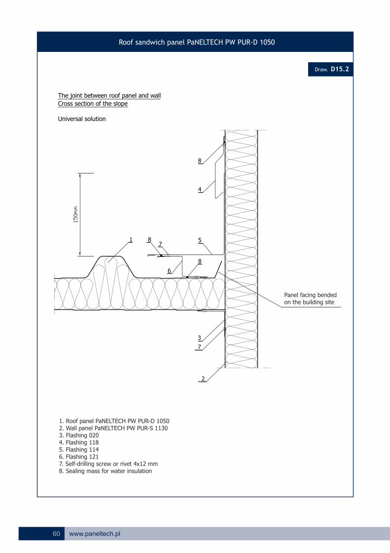
The joint between roof panel and wall
Cross section of the slope
Universal solution
2
8
4
5
6
78
8
Panel facing bended on the building site
1. Roof panel PaNELTECH PW PUR-D 10502. Wall panel PaNELTECH PW PUR-S 11303. Flashing 0204. Flashing 1185. Flashing 1146. Flashing 121 7. Self-drilling screw or rivet 4x12 mm8. Sealing mass for water insulation
61www.paneltech.pl
Draw.
Roof sandwich panel PaNELTECH PW PUR-D 1050
D15.3
1
2
9
10
11
128
3
8
6
7
4
5
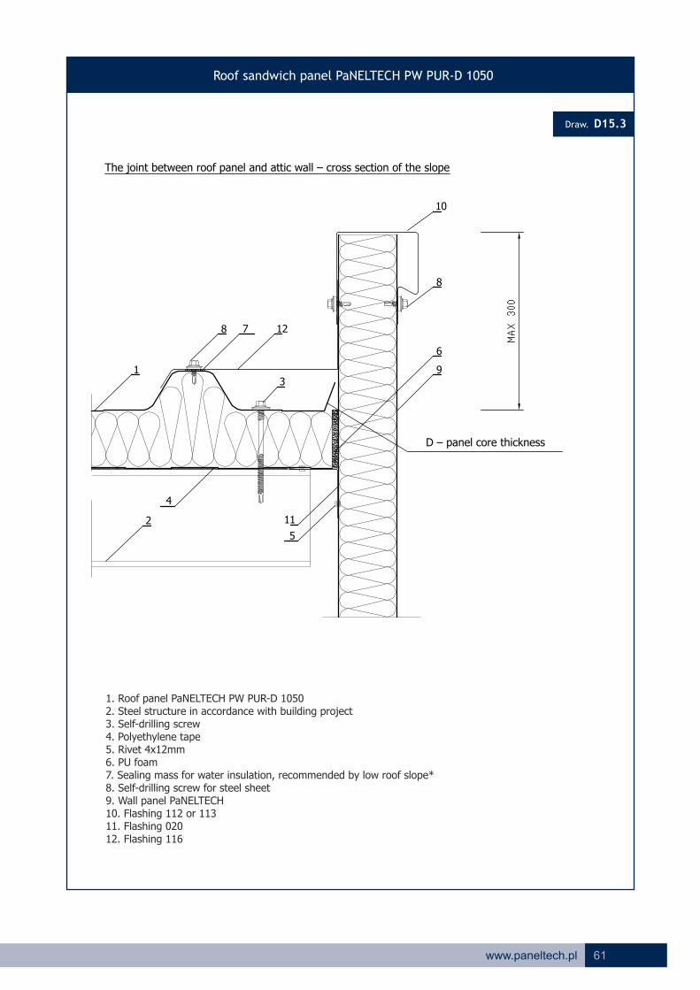
The joint between roof panel and attic wall – cross section of the slope
D – panel core thickness
1. Roof panel PaNELTECH PW PUR-D 10502. Steel structure in accordance with building project3. Self-drilling screw4. Polyethylene tape5. Rivet 4x12mm6. PU foam7. Sealing mass for water insulation, recommended by low roof slope*8. Self-drilling screw for steel sheet9. Wall panel PaNELTECH10. Flashing 112 or 11311. Flashing 02012. Flashing 116

62 www.paneltech.pl
Draw.
Roof sandwich panel PaNELTECH PW PUR-D 1050
D15.4
1 8 510
13
6
2
3
11
12
7 4*
9
9
The joint between roof panel and reinforced concrete wall
Shed roof – horizontal section of the slope
4*
1. Roof panel PaNELTECH PW PUR-D 10502. Reinforced concrete wall3. Fast installation pin4. Sealing mass for water insulation, recommended by low roof slope*5. Rivet 4x12mm6. PU foam7. PU gasket UD428. Self-drilling screw for steel sheet9. Sealing mass10. Flashing 10211. Flashing 11912. Flashing 11413. Flashing 020
*optional solution
63www.paneltech.pl
Draw.
Roof sandwich panel PaNELTECH PW PUR-D 1050
D18
13
7
12
7 5
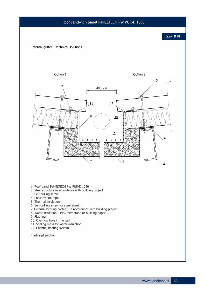
Internal gutter – technical solutions
9
11
10
11
Option 1 Option 2
1. Roof panel PaNELTECH PW PUR-D 10502. Steel structure in accordance with building project3. Self-drilling screw4. Polyethylene tape5. Thermal insulation6. Self-drilling screw for steel sheet7. External bearing profile – in accordance with building project8. Water insulation – PVC membrane or building paper9. Flashing10. Overflow hole in the wall11. Sealing mass for water insulation12. Channel heating system
* advised solution
64 www.paneltech.pl
Draw.
Roof sandwich panel PaNELTECH PW PUR-D 1050
D20.1
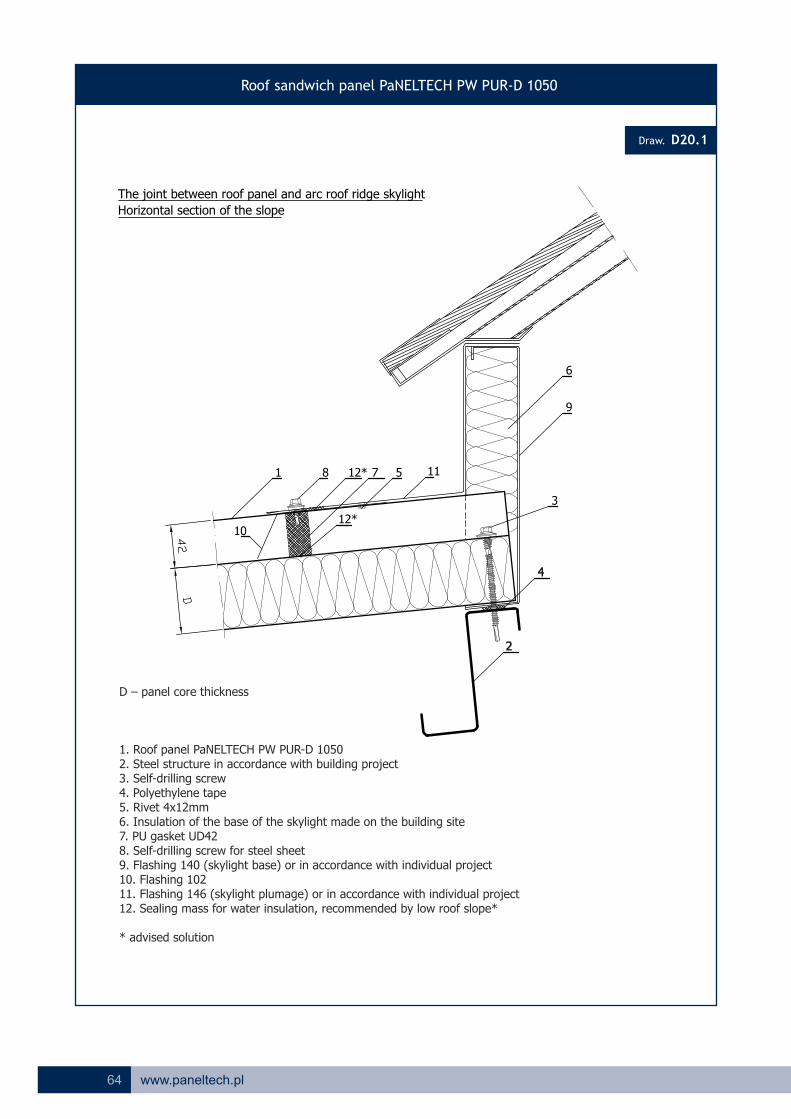
The joint between roof panel and arc roof ridge skylight
Horizontal section of the slope
9
1 8 5 11
3
12* 7
1012*
6
D – panel core thickness
1. Roof panel PaNELTECH PW PUR-D 10502. Steel structure in accordance with building project3. Self-drilling screw4. Polyethylene tape5. Rivet 4x12mm6. Insulation of the base of the skylight made on the building site7. PU gasket UD428. Self-drilling screw for steel sheet9. Flashing 140 (skylight base) or in accordance with individual project10. Flashing 10211. Flashing 146 (skylight plumage) or in accordance with individual project12. Sealing mass for water insulation, recommended by low roof slope*
* advised solution
65www.paneltech.pl
Draw.
Roof sandwich panel PaNELTECH PW PUR-D 1050
D22.2
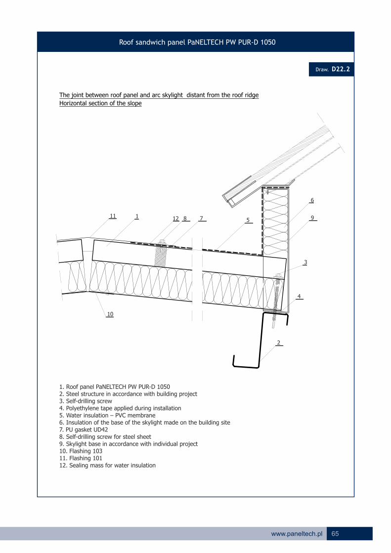
The joint between roof panel and arc skylight distant from the roof ridge
Horizontal section of the slope
1. Roof panel PaNELTECH PW PUR-D 10502. Steel structure in accordance with building project3. Self-drilling screw4. Polyethylene tape applied during installation5. Water insulation – PVC membrane6. Insulation of the base of the skylight made on the building site7. PU gasket UD428. Self-drilling screw for steel sheet9. Skylight base in accordance with individual project10. Flashing 10311. Flashing 10112. Sealing mass for water insulation
9
3
4
2
6
111 812 7
10
5

66 www.paneltech.pl
a b a - on extreme support
b - on middle support
ULS
2 2 2 2 2 2 2 2 2 2 2 2 2 2
L/100
L/150
L/200
ULS
2 2 2 2 2 2 2 2 2 2 2 2 2 2
L/100
L/150
L/200
ULS
2 2 2 2 2 2 2 2 2 2 2 2 2 2
L/100
L/150
L/200
ULS
2 4 2 4 2 4 2 4 2 4 2 3 2 3 2 2 2 2 2 2 2 2 2 2 2 2 2 2
L/100
L/150
L/200
ULS
2 4 2 4 2 4 2 4 2 4 2 3 2 3 2 2 2 2 2 2 2 2 2 2 2 2 2 2
L/100
L/150
L/200
ULS
2 4 2 4 2 4 2 3 2 3 2 3 2 2 2 2 2 2 2 2 2 2 2 2 2 2 2 2
L/100
L/150
L/200
ULS
2 4 2 4 2 4 2 3 2 3 2 3 2 3 2 2 2 2 2 2 2 2 2 2 2 2 2 2
L/100
L/150
L/200
ULS
2 4 2 4 2 4 2 4 2 3 2 3 2 3 2 2 2 2 2 2 2 2 2 2 2 2 2 2
L/100
L/150
L/200
ULS
2 4 2 4 2 4 2 3 2 3 2 3 2 2 2 2 2 2 2 2 2 2 2 2 2 2 2 2
L/100
L/150
L/200
Minimal width of extreme support 40 [mm]
1,96
2,36
2,99
2,23
2,76
3,49
2,10
2,55
3,21
4,72
2,48
3,10
4,10 3,86
2,97
2,38
3,734,31
2,97
3,86 3,49
2,76
2,10
2,55
3,21
3,053,343,73
2,36
2,99
4,31
2,38 2,23
2,362,552,762,97
3,86 3,49 3,21
3,23
4,02
2,573,09
3,09 2,57
2,43
2,91
3,66
2,73
4,31
3,73
3,12
3,66
4,50
4,24
5,15
4,31
3,66
4,24
5,15
2,43
2,91
3,66
2,73
3,23
4,02
4,31
5,15 4,50
3,73
3,73
3,12
3,66
4,50
3,66
4,30
3,73
3,66
4,31
4,24
3,12
3,66
2,63
3,09
2,43
2,91
3,66
2,57
3,72
4,38
3,19
2,73
3,23
4,02
5,29
4,07 3,54
4,89
4,31 3,73 3,19
2,68
3,15
3,023,44
3,72
4,38
3,44
4,07
4,895,29
2,63
2,85
2,40
3,54
2,68
3,15
3,87
3,87
5,29 4,89
4,72
2,40
2,85
3,54
3,02
3,54
4,30
4,31
3,54
2,63
3,15
3,87
3,19
3,54
4,30
3,73
3,72 3,023,44 2,68 2,40
2,854,074,38
5,286,10
6,49
5,31
4,53 4,07
4,78
5,81
6,49
5,31
4,53
5,81
4,78
4,07
4,64
6,49 5,81
5,31
4,53
6,10
4,78
4,07
5,28 4,72
3,994,99
5,20
6,10
6,16
5,15
4,42
5,28 4,72
5,59
5,15
4,42
3,40
6,94
5,84
6,16
5,84
4,99
5,88
5,59
5,84
4,99
3,66
4,64
3,99
4,72
5,15
4,42
5,15
4,42
5,20
5,15
4,50
4,64
3,99
4,72
5,28
6,16
6,16 6,94
4,99
5,84
5,88
6,94
5,59
3,10
4,81
5,85
5,15
5,41
4,725,205,88
2,75 3,19 3,19
6,94 6,94 6,16
6,08
4,104,334,613,863,68
2,65
5,28
4,33
3,24
2,58
5,28 6,10
4,61
2,482,582,712,71
3,42
6,10 6,10 5,28 4,72
3,42
4,61 4,33
3,24
4,10
3,10
1,0
4,72 4,31
4,33
3,24
1,2
3,053,343,73
6,10
2,71
5,28 3,053,34
5,28
0,80,4 0,5 0,6
5,28
4,65
3,74
5,11
6,10
4,00
6,104,72
-0,5
2,73
-0,4 -0,3 0,3
3,05 3,24
4,61
3,42
2,56
3,53
4,72
2,48
3,10
4,10
4,02
4,64
4,40
5,59
4,72
4,10
5,15 5,59
4,24
3,66
3,07 3,22
3,99
4,64
3,40
2,48
4,31
4,24
3,66
5,15
2,76
4,31
3,49
2,97
2,38
4,31
4,72
2,90
4,17
5,15 5,59 6,89
4,31
-0,6
4,04
3,27
4,31
3,86
4,07
4,89
5,28
4,14
6,16
4,96
4,724,31
3,44 3,75 4,57
5,55
4,89
5,81
4,43
5,29
4,52
6,495,815,294,89
4,31
3,54 3,87
4,72
4,27
5,28
4,07 4,38 4,78 5,31
4,07
5,00
4,533,72
4,02
5,61
4,42
4,83
3,39 3,60
4,494,14
3,85
6,204,84
3,02
3,32
4,30
3,42
5,18
3,21
3,73
3,44
4,30
3,54
3,04
3,73
4,30
3,54
3,86
2,85
4,50
3,64
2,97
3,73
2,83
3,66
3,12
3,60
4,50
3,66
3,12
3,73
3,19
2,34
3,71
4,50
3,10
2,55
3,73
3,64
2,94
2,48
3,73
3,49
2,76
2,23
3,19
3,87
3,15
2,68
3,04
3,87
3,23
2,63
3,27
3,87
3,15
2,68
2,87
4,02
3,23
2,73
2,70
4,02
3,01
2,23
2,96
4,02
3,23
2,32
3,34
3,30
2,69
2,26
3,34
3,21
2,55
2,10
3,34
3,54
2,85
2,40
2,49
3,54
2,84
2,37
2,71
3,54
2,85
2,40
2,63
3,66
2,91
2,43
2,25
3,66
2,91
Joints*
Joints*
Joints*
2,36
1,96
3,05
2,83
2,13
2,39
2,99
6,10
4,78
5,53
6,52
6,10
2,47
3,66
2,91
2,43
schemeColour group
Joints*
Joints*
Joints*
SLS
I
II
III
Joints*
I
II
III
SLS
Joints*
Joints*
SLS
-1,2 -1,0 -0,8
3,05
SLS
3,04
2,49
2,09
3,05
Minimal width of middle support 60 [mm]
SLS
SLS
2Characterictis loading [kN/m ]
SLS
SLS
do
ub
le-s
pan
syste
m
I
II
mu
ltis
pan
syste
m
SLS
Cryteria
Internal facing thickness 0,50 [mm]
External facing thickness 0,50 [mm]
sin
gle
-sp
an
syste
m
Required number of joints
Inside temperature + 25°C / + 20°C (summer/winter)
Outside temperature + 55°C, + 65°C, + 80°C, / - 20°C (summer/winter)
2,58
2,99
1,96
2Table 13. Maximal allowable spans for uniformly distributed wind characteristic load [kN/m ] for panel PW PUR-S 40 mm and PW PIR-S 40 mm.
LOAD BEARING TABLES FOR PW PUR-S, PW PUR-SU AND PW PUR-D PANELS
Static
ULS - Ultimate Limit StateSLS - Serviceability Limit State
III
1,962,102,38 2,232,122,061,991,941,841,751,68 2,39 2,392,39

ULS
3 3 2 2 2 2 2 2 2 2 2 2 2 2
L/100
L/150
L/200
ULS
3 3 2 2 2 2 2 2 2 2 2 2 2 2
L/100
L/150
L/200
ULS
3 3 2 2 2 2 2 2 2 2 2 2 2 2
L/100
L/150
L/200
ULS
2 4 2 4 2 4 2 4 2 4 2 4 2 4 2 2 2 2 2 2 2 2 2 2 2 2 2 2
L/100
L/150
L/200
ULS
2 4 2 4 2 4 2 4 2 4 2 4 2 3 2 2 2 2 2 2 2 2 2 2 2 2 2 2
L/100
L/150
L/200
ULS
2 4 2 4 2 4 2 4 2 4 2 3 2 3 2 2 2 2 2 2 2 2 2 2 2 2 2 2
L/100
L/150
L/200
ULS
2 4 2 4 2 4 2 4 2 4 2 4 2 3 2 2 2 2 2 2 2 2 2 2 2 2 2 2
L/100
L/150
L/200
ULS
2 4 2 4 2 4 2 4 2 4 2 4 2 3 2 2 2 2 2 2 2 2 2 2 2 2 2 2
L/100
L/150
L/200
ULS
2 4 2 4 2 4 2 4 2 4 2 3 2 3 2 2 2 2 2 2 2 2 2 2 2 2 2 2
L/100
L/150
L/200
3,74
SLS
SLS
SLS
SLS
SLS
I
II
SLS
-1,2 -1,0 -0,8
3,74
SLS
4,09
3,39
2,91
3,74
I
II
III
I
II
III
SLS
SLS
4,09
7,48
6,52
7,39
8,67
7,48
2,43
5,00
4,03
3,40
3,28
2,76
3,74
3,90
3,05
2,44
2,31
5,00
4,03
3,40
2,14
5,00
4,03
3,40
2,81
4,81
3,92
3,34
2,75
4,81
3,92
3,34
2,66
4,81
3,92
3,30
4,10
4,43
3,69
3,15
4,10
4,39
3,53
2,97
4,10
4,17
3,20
2,56
2,90
5,48
4,45
2,77
5,48
4,45
3,79
2,56
5,48
4,45
3,78
3,39
5,24
4,31
3,70
3,33
5,24
4,31
3,70
3,23
5,24
4,31
3,61
4,58
4,87
4,03
3,44
4,58
4,76
3,84
3,20
4,58
4,51
3,38
2,69
3,62
6,09
5,00
4,30
3,47
6,09
5,00
4,30
3,23
6,09
5,00
4,24
4,27
3,99 4,51
4,57
4,77
5,79
4,81
4,17
4,21
5,79
4,81
5,33
6,56
4,17
4,07
5,79
4,75
7,05 7,63
5,42
6,85
4,84 5,19
6,205,72
5,58
8,42
5,50 5,96 6,52 7,24
5,61
6,14
6,245,14
4,93
8,677,757,086,56
5,29
4,81 5,24
5,79
5,79
6,48
6,50
7,63
6,56
7,75
5,96
7,08
6,25
5,50
6,56
6,48
5,80
8,24
6,84
5,795,29
4,86 5,27
5,76
6,93 7,50 9,26
5,29
-0,6
5,47
4,49
5,29
5,27
3,84
5,84
4,78
4,22
3,43
5,29
5,79
4,10
4,83
3,59
4,86
2,84
5,76
5,00
6,93
5,76
5,00
3,77 3,94
5,48
6,27
5,40
7,50
5,79
2,93
4,70
6,93 7,50
5,02
5,79
3,57
4,41
5,60
5,48
6,27
-0,5
3,79
-0,4 -0,3 0,3
4,34 4,63
6,48
4,90
3,71
5,16
6,92
7,48
5,62
7,485,79
0,80,4 0,5 0,6
6,48
6,30
1,2
3,744,104,58
7,48
3,93
6,48 3,744,10
6,48
6,48 6,02
4,63
5,60
4,41
1,0
5,79 5,29
6,02
4,63
3,573,743,933,93
4,90
7,48 7,48 6,48 5,79
4,90
6,48
6,02
4,63
3,74
6,48 7,48
6,48
5,606,026,48
3,03 3,60 3,60 3,57
5,545,25
3,86 4,02 4,80 4,63
9,26 9,26 8,24
7,46
7,50
4,41
3,14
5,90
7,85
6,93
6,64
5,796,387,226,48
8,24
8,24 9,26
6,87
7,85
7,22
9,26
6,93
6,09
6,38
6,93
6,09
6,27
5,48
5,79
7,50
7,85
6,87
4,49
6,27
5,48
5,79
6,93
6,09
6,93
6,09
4,17
9,26
7,85
8,24
7,85
6,87
7,22
5,486,87
6,38
7,48
8,24
6,93
6,09
6,48 5,79
7,50
6,27
8,67 7,75
7,24
6,24
7,48
6,52
5,61
6,48 5,79
8,67
7,24
6,24
7,75
6,52
5,61
6,487,48
8,67
7,24
6,24 5,61
6,52
7,75
5,14 4,174,77 3,70 3,34
3,925,505,96
4,81
3,72
4,31
5,24
4,10
4,81
5,79
4,58
7,08 6,56
5,79
3,34
3,92
4,81
4,17
4,81
5,79
5,29
3,72
3,92
3,34
4,81
3,70
4,31
5,24
5,24
5,14
5,96
4,77
5,50
6,567,08
5,29 4,58 4,10
3,70
4,31
4,174,775,14
5,96
4,10
3,79
4,45
5,48
7,08
5,50 4,81
6,56
3,72
3,80
3,40
4,03
5,00
3,16
5,79
4,58
5,00
5,29
5,76
4,30
5,00
5,29
6,93 6,09
4,58
3,20
4,58
4,30
5,00
6,09
5,00 3,40
4,03
5,00
3,79
4,45
5,48
5,76
6,93
5,29
5,00
5,76
6,93
5,29
3,43
4,58
4,30
5,00
6,09
3,80 3,16
3,40
4,03
5,00
3,79
4,39 4,09
4,45
5,48
3,16
2,76
3,80
2,97
5,29
3,43 3,20 2,76
3,283,533,844,22
5,27 4,76
2,97
3,53
4,39
3,744,104,58
3,28
4,09
4,585,29
4,22
5,27 4,76
3,84
5,79
3,57
4,41
5,60 5,27
4,22
3,43 2,76
3,28
4,09
3,20
3,84
4,76
2,97
3,53
4,39
67www.paneltech.pl
2Table 14. Maximal allowable spans for uniformly distributed wind characteristic load [kN/m ] for panel PW PUR-S 60 mm and PW PIR-S 60 mm.
a b a - on extreme support
b - on middle support
Minimal width of extreme support 40 [mm]
Minimal width of middle support 60 [mm]
Internal facing thickness 0,50 [mm]
External facing thickness 0,50 [mm]
Required number of joints
Inside temperature + 25°C / + 20°C (summer/winter)
Outside temperature + 55°C, + 65°C, + 80°C, / - 20°C (summer/winter)
Joints*
Joints*
Joints*
schemeColour group
Joints*
Joints*
Joints*
Joints*
Joints*
Joints*
2Characterictis loading [kN/m ]
do
ub
le-s
pan
syste
mm
ult
isp
an
syste
m
Cryteria
sin
gle
-sp
an
syste
m
Static
ULS - Ultimate Limit StateSLS - Serviceability Limit State
III
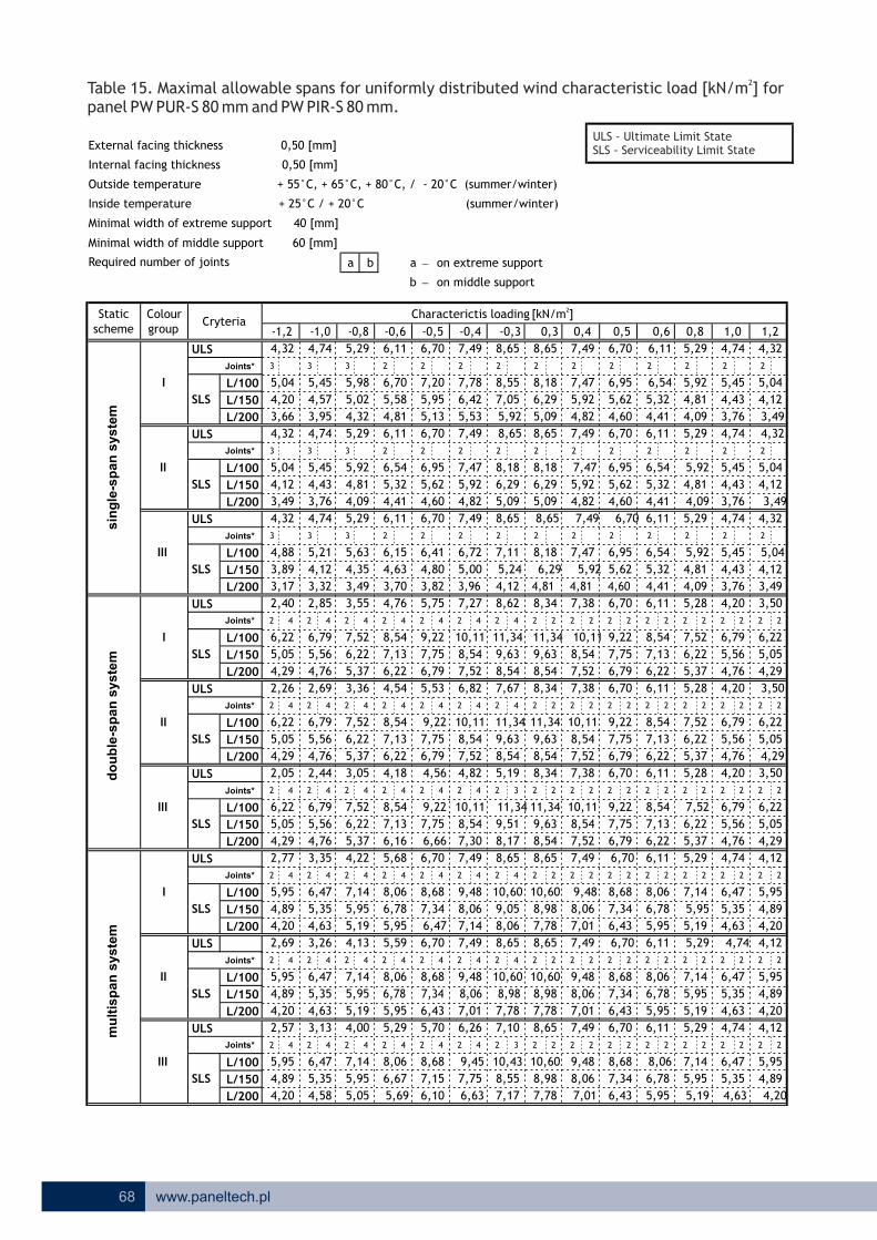
ULS
3 3 3 2 2 2 2 2 2 2 2 2 2 2
L/100
L/150
L/200
ULS
3 3 3 2 2 2 2 2 2 2 2 2 2 2
L/100
L/150
L/200
ULS
3 3 3 2 2 2 2 2 2 2 2 2 2 2
L/100
L/150
L/200
ULS
2 4 2 4 2 4 2 4 2 4 2 4 2 4 2 2 2 2 2 2 2 2 2 2 2 2 2 2
L/100
L/150
L/200
ULS
2 4 2 4 2 4 2 4 2 4 2 4 2 4 2 2 2 2 2 2 2 2 2 2 2 2 2 2
L/100
L/150
L/200
ULS
2 4 2 4 2 4 2 4 2 4 2 4 2 3 2 2 2 2 2 2 2 2 2 2 2 2 2 2
L/100
L/150
L/200
ULS
2 4 2 4 2 4 2 4 2 4 2 4 2 4 2 2 2 2 2 2 2 2 2 2 2 2 2 2
L/100
L/150
L/200
ULS
2 4 2 4 2 4 2 4 2 4 2 4 2 4 2 2 2 2 2 2 2 2 2 2 2 2 2 2
L/100
L/150
L/200
ULS
2 4 2 4 2 4 2 4 2 4 2 4 2 3 2 2 2 2 2 2 2 2 2 2 2 2 2 2
L/100
L/150
L/200
4,82
SLS
SLS
SLS
SLS
SLS
I
II
III
SLS
-1,2 -1,0 -0,8
4,32
SLS
5,04
4,20
3,66
4,32
I
II
III
I
II
III
SLS
SLS
5,04
8,65
8,06
9,05
10,60
8,65
2,40
6,22
5,05
4,29
4,12
3,49
4,32
4,88
3,89
3,17
2,26
6,22
5,05
4,29
2,05
6,22
5,05
4,29
2,77
5,95
4,89
4,20
2,69
5,95
4,89
4,20
2,57
5,95
4,89
4,20
4,74
5,45
4,57
3,95
4,74
5,45
4,43
3,76
4,74
5,21
4,12
3,32
2,85
6,79
5,56
2,69
6,79
5,56
4,76
2,44
6,79
5,56
4,76
3,35
6,47
5,35
4,63
3,26
6,47
5,35
4,63
3,13
6,47
5,35
4,58
5,29
5,98
5,02
4,32
5,29
5,92
4,81
4,09
5,29
5,63
4,35
3,49
3,55
7,52
6,22
5,37
3,36
7,52
6,22
5,37
3,05
7,52
6,22
5,37
4,22
5,05 5,69
5,29
5,95
7,14
5,95
5,19
4,13
7,14
5,95
6,67
8,06
5,19
4,00
7,14
5,95
8,68 9,45
6,26
8,55
6,10 6,63
7,757,15
7,17
10,43
6,78 7,34 8,06 8,98
7,01
7,10
7,786,43
5,70
10,609,488,688,06
5,59
5,95 6,47
6,70
7,14
7,49
8,17
9,51
8,06
9,48
7,34
8,68
7,75
6,78
8,06
7,49
7,30
10,11
8,54
6,705,68
6,16 6,66
7,13
8,54 9,22 11,34
6,11
-0,6
6,70
5,58
6,11
6,54
4,81
7,20
5,95
5,32
4,41
6,11
6,70
5,13
6,15
4,63
4,76
3,70
7,13
6,22
8,54
7,13
6,22
4,18 4,56
6,79
7,75
5,53
9,22
5,75
3,82
4,54
8,54 9,22
6,41
6,70
4,60
5,62
6,95
6,79
7,75
-0,5
4,76
-0,4 -0,3 0,3
5,53 5,92
8,18
6,29
4,80
6,42
8,55
8,65
7,05
8,656,70
0,80,4 0,5 0,6
7,49
7,78
1,2
4,324,745,29
8,65
5,09
7,49 4,324,74
7,49
8,18 7,47
5,92
6,95
5,62
1,0
6,70 6,11
7,47
5,92
4,604,825,095,09
6,29
8,65 8,65 7,49 6,70
6,29
7,49
7,47
5,92
4,82
7,49 8,65
8,18
6,957,478,18
3,96 4,81 4,81 4,60
7,116,72
5,00 5,24 6,29 5,92
11,34 11,34 10,11
8,62
9,22
5,62
4,12
6,82
9,63
8,54
7,67
6,707,388,347,27
10,11
10,11 11,34
8,54
9,63
8,34
11,34
8,54
7,52
7,38
8,54
7,52
7,75
6,79
6,70
9,22
9,63
8,54
5,19
7,75
6,79
6,70
8,54
7,52
8,54
7,52
4,82
11,34
9,63
10,11
9,63
8,54
8,34
6,798,54
7,38
8,65
10,11
8,54
7,52
7,49 6,70
9,22
7,75
10,60 9,48
8,98
7,78
8,65
8,06
7,01
7,49 6,70
10,60
8,98
7,78
9,48
8,06
7,01
7,498,65
10,60
8,98
7,78 7,01
8,06
9,48
6,43 5,195,95 4,63 4,20
4,896,787,34
5,95
4,12
5,35
6,47
4,74
5,95
7,14
5,29
8,68 8,06
6,70
4,20
4,89
5,95
5,19
5,95
7,14
6,11
4,12
4,89
4,20
5,95
4,63
5,35
6,47
6,47
6,43
7,34
5,95
6,78
8,068,68
6,11 5,29 4,74
4,63
5,35
5,195,956,43
7,34
4,74
4,76
5,56
6,79
8,68
6,78 5,95
8,06
4,12
4,20
4,29
5,05
6,22
3,50
7,14
5,29
6,22
6,11
7,13
5,37
6,22
6,11
8,54 7,52
5,28
4,09
5,28
5,37
6,22
7,52
6,22 4,29
5,05
6,22
4,76
5,56
6,79
7,13
8,54
6,11
6,22
7,13
8,54
6,11
4,41
5,28
5,37
6,22
7,52
4,20 3,50
4,29
5,05
6,22
4,76
5,45 5,04
5,56
6,79
3,50
3,49
4,20
3,76
6,11
4,41 4,09 3,49
4,124,434,815,32
6,54 5,92
3,76
4,43
5,45
4,324,745,29
4,12
5,04
5,296,11
5,32
6,54 5,92
4,81
6,70
4,60
5,62
6,95 6,54
5,32
4,41 3,49
4,12
5,04
4,09
4,81
5,92
3,76
4,43
5,45
68 www.paneltech.pl
2Table 15. Maximal allowable spans for uniformly distributed characteristic load [kN/m ] for panel PW PUR-S 80 mm and PW PIR-S 80 mm.
wind
a b a - on extreme support
b - on middle support
Minimal width of extreme support 40 [mm]
Minimal width of middle support 60 [mm]
Internal facing thickness 0,50 [mm]
External facing thickness 0,50 [mm]
Required number of joints
Inside temperature + 25°C / + 20°C (summer/winter)
Outside temperature + 55°C, + 65°C, + 80°C, / - 20°C (summer/winter)
Joints*
Joints*
Joints*
schemeColour group
Joints*
Joints*
Joints*
Joints*
Joints*
Joints*
2Characterictis loading [kN/m ]
do
ub
le-s
pan
syste
mm
ult
isp
an
syste
m
Cryteria
sin
gle
-sp
an
syste
m
Static
ULS - Ultimate Limit StateSLS - Serviceability Limit State
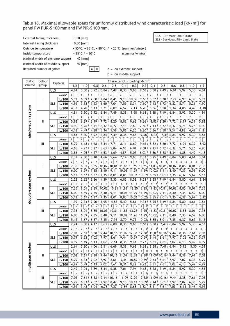
ULS
3 3 3 3 2 2 2 2 2 2 2 2 2 2
L/100
L/150
L/200
ULS
3 3 3 3 2 2 2 2 2 2 2 2 2 2
L/100
L/150
L/200
ULS
3 3 3 3 2 2 2 2 2 2 2 2 2 2
L/100
L/150
L/200
ULS
2 4 2 4 2 4 2 4 2 4 2 4 2 4 2 2 2 2 2 2 2 2 2 2 2 2 2 2
L/100
L/150
L/200
ULS
2 4 2 4 2 4 2 4 2 4 2 4 2 4 2 2 2 2 2 2 2 2 2 2 2 2 2 2
L/100
L/150
L/200
ULS
2 4 2 4 2 4 2 4 2 4 2 4 2 4 2 2 2 2 2 2 2 2 2 2 2 2 2 2
L/100
L/150
L/200
ULS
2 4 2 4 2 4 2 4 2 4 2 4 2 4 2 2 2 2 2 2 2 2 2 2 2 2 2 2
L/100
L/150
L/200
ULS
2 4 2 4 2 4 2 4 2 4 2 4 2 4 2 2 2 2 2 2 2 2 2 2 2 2 2 2
L/100
L/150
L/200
ULS
2 4 2 4 2 4 2 4 2 4 2 4 2 3 2 2 2 2 2 2 2 2 2 2 2 2 2 2
L/100
L/150
L/200
5,86
SLS
SLS
SLS
SLS
SLS
I
II
III
SLS
-1,2 -1,0 -0,8
4,84
SLS
5,92
4,95
4,33
4,84
I
II
III
I
II
III
SLS
SLS
5,92
9,68
9,44
10,59
12,38
9,68
2,37
7,35
6,00
5,12
4,90
4,18
4,84
5,79
4,65
3,86
2,22
7,35
6,00
5,12
1,99
7,35
6,00
5,12
2,74
7,02
5,79
4,99
2,64
7,02
5,79
4,99
2,49
7,02
5,79
4,99
5,30
6,39
5,38
4,70
5,30
6,39
5,26
4,49
5,30
6,18
4,97
4,05
2,80
8,01
6,59
2,62
8,01
6,59
5,67
2,34
8,01
6,59
5,67
3,30
7,61
6,33
5,49
3,20
7,61
6,33
5,49
3,04
7,61
6,33
5,48
5,92
7,00
5,92
5,13
5,92
6,99
5,71
4,88
5,92
6,68
5,27
4,27
3,48
8,85
7,35
6,37
3,26
8,85
7,35
6,37
2,90
8,85
7,35
6,37
4,17
6,04 6,78
5,34
7,02
8,38
7,02
6,13
4,06
8,38
7,02
7,92
9,44
6,13
3,89
8,38
7,02
10,16 11,09
7,01
10,13
7,27 7,89
9,188,47
8,68
12,29
7,97 8,61 9,44 10,59
8,31
7,94
9,227,61
6,38
12,3811,0910,169,44
5,51
7,02 7,61
6,69
8,38
8,38
9,72
11,26
9,44
11,09
8,61
10,16
9,11
7,97
9,44
8,38
8,70
11,83
10,02
6,805,63
7,35 7,95
8,40
10,02 10,81 13,25
6,84
-0,6
7,84
6,60
6,84
7,72
5,71
8,41
7,04
6,32
5,34
6,84
7,49
6,09
7,34
5,63
4,66
4,53
8,40
7,35
10,02
8,40
7,35
3,95 4,88
8,01
9,11
5,35
10,81
5,64
4,69
4,39
10,02 10,81
7,71
7,49
5,58
6,72
8,20
8,01
9,11
-0,5
5,67
-0,4 -0,3 0,3
6,57 7,13
9,66
7,60
5,84
7,59
10,06
9,68
8,34
9,687,49
0,80,4 0,5 0,6
8,38
9,15
1,2
4,845,305,92
9,68
6,20
8,38 4,845,30
8,38
9,66 8,82
7,13
8,20
6,72
1,0
7,49 6,84
8,82
7,13
5,585,866,206,20
7,60
9,68 9,68 8,38 7,49
7,60
8,38
8,82
7,13
5,86
8,38 9,68
9,66
8,208,829,66
4,87 6,03 5,86 5,58
8,608,11
6,10 6,40 7,60 7,13
13,25 13,25 11,83
9,65
10,81
6,72
5,07
6,85
11,29
10,02
8,58
7,498,259,337,14
11,83
11,83 13,25
10,02
11,29
9,33
13,25
10,02
8,85
8,25
10,02
8,85
9,11
8,01
7,49
10,81
11,29
10,02
5,81
9,11
8,01
7,49
10,02
8,85
10,02
8,85
5,40
13,25
11,29
11,83
11,29
10,02
9,33
8,0110,02
8,25
9,68
11,83
10,02
8,85
8,38 7,49
10,81
9,11
12,38 11,09
10,59
9,22
9,68
9,44
8,31
8,38 7,49
12,38
10,59
9,22
11,09
9,44
8,31
8,389,68
12,38
10,59
9,22 8,31
9,44
11,09
7,61 6,137,02 5,49 4,99
5,797,978,61
7,02
4,53
6,33
7,61
5,30
7,02
8,38
5,92
10,16 9,44
7,49
4,99
5,79
7,02
6,13
7,02
8,38
6,84
4,53
5,79
4,99
7,02
5,49
6,33
7,61
7,61
7,61
8,61
7,02
7,97
9,4410,16
6,84 5,92 5,30
5,49
6,33
6,137,027,61
8,61
5,30
5,67
6,59
8,01
10,16
7,97 7,02
9,44
4,53
4,61
5,12
6,00
7,35
3,84
8,38
5,92
7,35
6,84
8,40
6,37
7,35
6,84
10,02 8,85
5,80
4,88
5,80
6,37
7,35
8,85
7,35 5,12
6,00
7,35
5,67
6,59
8,01
8,40
10,02
6,84
7,35
8,40
10,02
6,84
5,34
5,80
6,37
7,35
8,85
4,61 3,84
5,12
6,00
7,35
5,67
6,39 5,92
6,59
8,01
3,84
4,18
4,61
4,49
6,84
5,34 4,88 4,18
4,905,265,716,32
7,72 6,99
4,49
5,26
6,39
4,845,305,92
4,90
5,92
5,926,84
6,32
7,72 6,99
5,71
7,49
5,58
6,72
8,20 7,72
6,32
5,34 4,18
4,90
5,92
4,88
5,71
6,99
4,49
5,26
6,39
69www.paneltech.pl
2Table 16. Maximal allowable spans for uniformly distributed characteristic load [kN/m ] for panel PW PUR-S 100 mm and PW PIR-S 100 mm.
wind
a b a - on extreme support
b - on middle support
Minimal width of extreme support 40 [mm]
Minimal width of middle support 60 [mm]
Internal facing thickness 0,50 [mm]
External facing thickness 0,50 [mm]
Required number of joints
Inside temperature + 25°C / + 20°C (summer/winter)
Outside temperature + 55°C, + 65°C, + 80°C, / - 20°C (summer/winter)
Joints*
Joints*
Joints*
schemeColour group
Joints*
Joints*
Joints*
Joints*
Joints*
Joints*
2Characterictis loading [kN/m ]
do
ub
le-s
pan
syste
mm
ult
isp
an
syste
m
Cryteria
sin
gle
-sp
an
syste
m
Static
ULS - Ultimate Limit StateSLS - Serviceability Limit State

ULS
SLS
2Characterictis loading [kN/m ]scheme
Colour group
Static
do
ub
le-s
pan
syste
mm
ult
isp
an
syste
msin
gle
-sp
an
syste
m
70 www.paneltech.pl
2Table 17. Maximal allowable spans for uniformly distributed characteristic load [kN/m ] for panel PW PUR-S 120 mm and PW PIR-S 120 mm.
wind
a b a - on extreme support
b - on middle support
Minimal width of extreme support 40 [mm]
Minimal width of middle support 60 [mm]
Internal facing thickness 0,50 [mm]
External facing thickness 0,50 [mm]
Required number of joints
Inside temperature + 25°C / + 20°C (summer/winter)
Outside temperature + 55°C, + 65°C, + 80°C, / - 20°C (summer/winter)
Joints*
ULS - Ultimate Limit StateSLS - Serviceability Limit State
4,87 5,81 6,49 7,50 8,21 9,18 10,61 10,61 9,18 8,21 7,50 6,49 5,81
3 3 3 3 3 2 2 2 2 2 2 2 2
6,74 7,27 7,95 8,90 9,54 10,37 11,48 11,05 10,09 9,38 8,83 7,95 7,27
5,66 6,13 6,74 7,56 8,06 8,69 9,55 8,85 8,29 7,71 7,26 6,56 6,05
4,96 5,40 5,90 6,56 7,00 7,55 8,29 7,27 6,85 6,51 6,23 5,64 5,18
4,87 5,81 6,49 7,50 8,21 9,18 10,61 10,61 9,18 8,21 7,50 6,49 5,81
3 3 3 3 3 2 2 2 2 2 2 2 2
6,74 7,27 7,95 8,83 9,38 10,09 11,05 11,05 10,09 9,38 8,83 7,95 7,27
5,64 6,05 6,56 7,26 7,71 8,29 8,85 8,85 8,29 7,71 7,26 6,56 6,05
4,83 5,18 5,64 6,23 6,51 6,85 7,27 7,27 6,85 6,51 6,23 5,64 5,18
4,87 5,81 6,49 7,50 8,21 9,18 10,61 10,61 9,18 8,21 7,50 6,49 5,81
3 3 3 3 3 2 2 2 2 2 2 2 2
6,65 7,09 7,66 8,42 8,93 9,43 10,02 11,05 10,09 9,38 8,83 7,95 7,27
5,36 5,73 6,15 6,58 6,84 7,15 7,52 8,85 8,29 7,71 7,26 6,56 6,05
2,35 2,77 3,42 4,57 5,53 7,01 9,55 10,23 9,04 8,21 7,50 5,73 4,56
2 4 2 4 2 4 2 4 2 4 2 4 2 4 2 2 2 2 2 2 2 2 2 2 2 2
8,41 9,15 10,10 11,41 12,30 13,45 15,04 15,04 13,45 12,30 11,41 10,10 9,15
6,89 7,56 8,41 9,59 10,39 11,41 12,83 12,83 11,41 10,39 9,59 8,41 7,56
5,91 6,53 7,32 8,41 9,15 10,10 11,41 11,41 10,10 9,15 8,41 7,32 6,53
2,18 2,77 3,42 4,57 5,53 7,01 9,55 10,23 9,04 8,21 7,50 5,73 4,56
2 4 2 4 2 4 2 4 2 4 2 4 2 4 2 2 2 2 2 2 2 2 2 2 2 2
8,41 9,15 10,10 11,41 12,30 13,45 15,04 15,04 13,45 12,30 11,41 10,10 9,15
6,89 7,56 8,41 9,59 10,39 11,37 12,62 12,83 11,41 10,39 9,59 8,41 7,56
5,91 6,53 7,32 8,41 9,15 10,10 11,41 11,41 10,10 9,15 8,41 7,32 6,53
1,95 2,27 2,78 3,74 4,61 5,91 6,36 10,23 9,04 8,21 7,50 5,73 4,56
2 4 2 4 2 4 2 4 2 4 2 4 2 4 2 2 2 2 2 2 2 2 2 2 2 2
8,41 9,15 10,10 11,41 12,30 13,45 15,04 15,04 13,45 12,30 11,41 10,10 9,15
6,89 7,56 8,41 9,59 10,39 11,41 12,83 12,83 11,41 10,39 9,59 8,41 7,56
5,91 6,53 7,32 8,41 9,15 10,02 11,18 11,41 10,10 9,15 8,41 7,32 6,53
2,70 3,26 4,12 5,57 6,74 8,51 10,61 10,61 9,18 8,21 7,50 6,49 5,44
2 4 2 4 2 4 2 4 2 4 2 4 2 4 2 2 2 2 2 2 2 2 2 2 2 2
8,01 8,68 9,54 10,74 11,54 12,59 14,04 14,04 12,59 11,54 10,74 9,54 8,68
6,64 7,24 8,01 9,08 9,80 10,74 12,03 12,03 10,74 9,80 9,08 8,01 7,24
5,74 6,30 7,02 8,01 8,68 9,54 10,74 10,57 9,53 8,68 8,01 7,02 6,30
2,59 3,14 3,99 5,44 6,61 8,37 10,61 10,61 9,18 8,21 7,50 6,49 5,44
2 4 2 4 2 4 2 4 2 4 2 4 2 4 2 2 2 2 2 2 2 2 2 2 2 2
8,01 8,68 9,54 10,74 11,54 12,59 14,04 14,04 12,59 11,54 10,74 9,54 8,68
6,64 7,24 8,01 9,08 9,80 10,74 12,03 12,03 10,74 9,80 9,08 8,01 7,24
5,74 6,30 7,02 8,01 8,68 9,53 10,57 10,57 9,53 8,68 8,01 7,02 6,30
2,41 2,95 3,78 5,22 6,39 7,68 8,70 10,61 9,18 8,21 7,50 6,49 5,44
2 4 2 4 2 4 2 4 2 4 2 4 2 4 2 2 2 2 2 2 2 2 2 2 2 2
8,01 8,68 9,54 10,74 11,54 12,59 14,04 14,04 12,59 11,54 10,74 9,54 8,68
6,64 7,24 8,01 9,08 9,72 10,53 11,62 12,03 10,74 9,80 9,08 8,01 7,24
5,74 6,30 6,97 7,82 8,38 9,09 10,04 10,57 9,53 8,68 8,01 7,02 6,30
5,30
2
6,74
5,64
4,83
5,30
2
6,74
5,64
4,83
5,30
2
6,74
5,64
3,80
2 2
8,41
6,89
5,91
3,80
2 2
8,41
6,89
5,91
3,80
2 3
8,41
6,89
5,91
4,50
2 2
8,01
6,64
5,74
4,50
2 2
8,01
6,64
5,74
4,50
2 2
8,01
6,64
5,74
L/100
L/150
L/200
L/100
L/150
L/200
L/100
L/150
L/200
L/100
L/150
L/200
L/100
L/150
L/200
L/100
L/150
L/200
L/100
L/150
L/200
L/100
L/150
L/200
L/100
L/150
L/200
I
II
III
-1,2 -1,0 -0,8
I
II
III
I
II
III
-0,6 -0,5 -0,4 -0,3 0,3 0,80,4 0,5 0,6 1,21,0
4,53 4,75 5,01 5,33 5,74 6,00 5,646,23 5,18 4,837,24 6,516,855,52
ULS
SLS
Joints*
ULS
SLS
Joints*
ULS
SLS
Joints*
ULS
SLS
Joints*
ULS
SLS
Joints*
ULS
SLS
Joints*
ULS
SLS
Joints*
ULS
SLS
Joints*
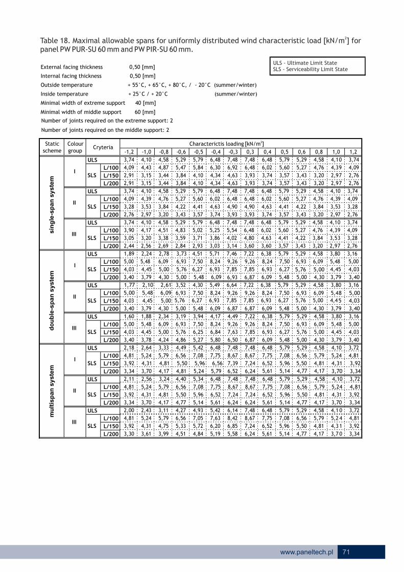
ULS
L/100
L/150
L/200
ULS
L/100
L/150
L/200
ULS
L/100
L/150
L/200
ULS
L/100
L/150
L/200
ULS
L/100
L/150
L/200
ULS
L/100
L/150
L/200
ULS
L/100
L/150
L/200
ULS
L/100
L/150
L/200
ULS
L/100
L/150
L/200
-1,2 -1,0 -0,8 -0,6 -0,5 -0,4 -0,3 0,3 0,4 0,5 0,6 0,8 1,0 1,2
I
3,74 4,10 4,58 5,29 5,79 6,48 7,48 7,48 6,48 5,79 5,29 4,58 4,10 3,74
SLS
4,09 4,43 4,87 5,47 5,84 6,30 6,92 6,48 6,02 5,60 5,27 4,76 4,39 4,09
2,91 3,15 3,44 3,84 4,10 4,34 4,63 3,93 3,74 3,57 3,43 3,20 2,97 2,76
2,91 3,15 3,44 3,84 4,10 4,34 4,63 3,93 3,74 3,57 3,43 3,20 2,97 2,76
II
3,74 4,10 4,58 5,29 5,79 6,48 7,48 7,48 6,48 5,79 5,29 4,58 4,10 3,74
SLS
4,09 4,39 4,76 5,27 5,60 6,02 6,48 6,48 6,02 5,60 5,27 4,76 4,39 4,09
3,28 3,53 3,84 4,22 4,41 4,63 4,90 4,90 4,63 4,41 4,22 3,84 3,53 3,28
2,76 2,97 3,20 3,43 3,57 3,74 3,93 3,93 3,74 3,57 3,43 3,20 2,97 2,76
III
3,74 4,10 4,58 5,29 5,79 6,48 7,48 7,48 6,48 5,79 5,29 4,58 4,10 3,74
SLS
3,90 4,17 4,51 4,83 5,02 5,25 5,54 6,48 6,02 5,60 5,27 4,76 4,39 4,09
3,05 3,20 3,38 3,59 3,71 3,86 4,02 4,80 4,63 4,41 4,22 3,84 3,53 3,28
2,44 2,56 2,69 2,84 2,93 3,03 3,14 3,60 3,60 3,57 3,43 3,20 2,97 2,76
I
1,89 2,24 2,78 3,73
II
1,77 2,10 2,61
4,51 5,71 7,46 7,22 6,38 5,79 5,29 4,58 3,80 3,16
SLS
5,00 5,48 6,09 6,93
4,03 4,45 5,00 5,76
6,93 6,09 5,48 5,00
6,93 6,87
7,85 7,85 6,93 6,27
3,79 3,40
4,45 4,03
3,40 3,79 4,30 5,00 5,48 6,09 6,09 5,48 5,00 4,30
5,79 5,29 4,58 3,80 3,163,52 4,30 5,49 6,64 7,22 6,38
SLS
5,00 5,48 6,09 8 5,00
4,03 4,45 5,00 5 4,03
3,40 3,79 4,30 5,00 5,48 6,09 6,87 6,87 6,09 5,48 5,00 4,30 3,79 3,40
III
1,60 1,88 2,34 3,19 3,94 4,17 4,49 7,22 6,38 5,79 5,29 4,58 3,80 3,16
SLS
5,00 5,48 6,09 6,93 7,50 8,24 9,26 9,26 8,24 7,50 6,93 6,09 5,48 5,00
4,03 4,45 5,00 5,76 6,25 6,84 7,63 7,85 6,93 6,27 5,76 5,00 4,45 4,03
3,40 3,78 4,24 4,86 5,27 5,80 6,50 6,87 6,09 5,48 5,00 4,30 3,79 3,40
I
2,18 2,64 3,33 4,49
II
2,11 2,56 3,24
5,42 6,48 7,48 7,48 6,48 5,79 5,29 4,58 4,10 3,72
SLS
4,81 5,24 5,79 6,56 7,08 7,75 8,67 8,67 7,75 7,08
3,92 4,31 4,81 5,50 5,96 6,56 5,50 4,81
6,56 5,79 5,24 4,81
6,52 6,24
7,39 7,24 6,52 5,96
3,70 3,34
4,31 3,92
3,34 3,70 4,17 4,81 5,24 5,79
5,79 5,29 4,58 4,10 3,724,40 5,34 6,48 7,48 7,48 6,48
SLS
4,81 5,24 5,79 6,56 7,08 7,75 8,67 8,67 7,75 7,08 6,56 5,79 5,24 4,81
3,92 4,31 4,81 5,50 5,96 6,52 7,24 7,24 6,52 5,96 5,50 4,81 4,31 3,92
3,34 3,70 4,17 4,77 5,14 5,61 6,24 6,24 5,61 5,14 4,77 4,17 3,70 3,34
III
2,00 2,43 3,11 4,27 4,93 5,42 6,14 7,48 6,48 5,79 5,29 4,58 4,1 0 3,72
SLS
4,81 5,24 5,79 6,56 7,05 7,63 8,42 8,67 7,75 7,08 6,56 5,79 5,2 4 4,81
3,92 4,31 4,75 5,33 5,72 6,20 6,85 7,24 6,52 5,96 5,50 4,81 4,3 1 3,92
3,30 3,61 3,99 4,51 4,84 5,19 5,58 6,24 5,61 5,14 4,77 4,17 3,7 0 3,34
7,50 8,24 9,26 9,26 8,24 7,50
5,76 5,00 6,27 6,93
6,93 7,50 8,24 9,26 9,26 8,24 7,50 6,93 6,09 5,4
5,76 6,27 6,93 7,85 7,85 6,93 6,27 5,76 5,00 4,4
5,61 5,14 4,77 4,17
Number of joints required on the extreme support: 2
2Table 18. Maximal allowable spans for uniformly distributed characteristic load [kN/m ] for panel PW PUR-SU 60 mm and PW PIR-SU 60 mm.
wind
Number of joints required on the middle support: 2
schemeColour group
2Characterictis loading [kN/m ]
do
ub
le-s
pan
syste
mm
ult
isp
an
syste
m
Cryteria
sin
gle
-sp
an
syste
m
Static
Minimal width of extreme support 40 [mm]
Minimal width of middle support 60 [mm]
Internal facing thickness 0,50 [mm]
External facing thickness 0,50 [mm]
Inside temperature + 25°C / + 20°C (summer/winter)
Outside temperature + 55°C, + 65°C, + 80°C, / - 20°C (summer/winter)
71www.paneltech.pl
ULS - Ultimate Limit StateSLS - Serviceability Limit State
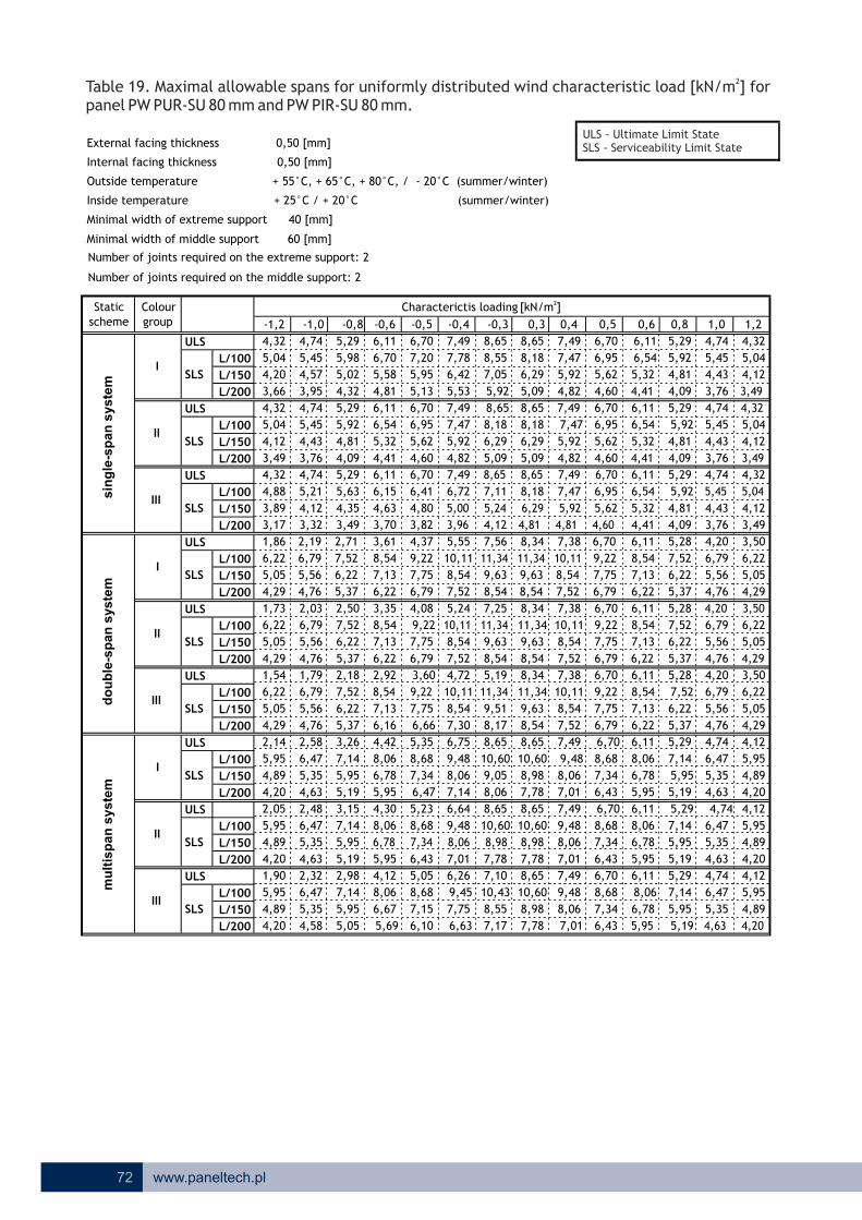
ULS
L/100
L/150
L/200
ULS
L/100
L/150
L/200
ULS
L/100
L/150
L/200
ULS
L/100
L/150
L/200
ULS
L/100
L/150
L/200
ULS
L/100
L/150
L/200
ULS
L/100
L/150
L/200
ULS
L/100
L/150
L/200
ULS
L/100
L/150
L/200
4,82
SLS
SLS
SLS
SLS
SLS
I
II
III
SLS
-1,2 -1,0 -0,8
4,32
SLS
5,04
4,20
3,66
4,32
I
II
III
I
II
IIISLS
SLS
5,04
8,65
8,06
9,05
10,60
8,65
1,86
6,22
5,05
4,29
4,12
3,49
4,32
4,88
3,89
3,17
1,73
6,22
5,05
4,29
1,54
6,22
5,05
4,29
2,14
5,95
4,89
4,20
2,05
5,95
4,89
4,20
1,90
5,95
4,89
4,20
4,74
5,45
4,57
3,95
4,74
5,45
4,43
3,76
4,74
5,21
4,12
3,32
2,19
6,79
5,56
2,03
6,79
5,56
4,76
1,79
6,79
5,56
4,76
2,58
6,47
5,35
4,63
2,48
6,47
5,35
4,63
2,32
6,47
5,35
4,58
5,29
5,98
5,02
4,32
5,29
5,92
4,81
4,09
5,29
5,63
4,35
3,49
2,71
7,52
6,22
5,37
2,50
7,52
6,22
5,37
2,18
7,52
6,22
5,37
3,26
5,05 5,69
4,12
5,95
7,14
5,95
5,19
3,15
7,14
5,95
6,67
8,06
5,19
2,98
7,14
5,95
5,05
8,68 9,45
6,26
8,55
6,10 6,63
7,757,15
7,17
10,43
6,78 7,34 8,06 8,98
7,01
7,10
7,786,43
10,609,488,688,06
4,30
5,95 6,47
5,23
7,14
6,64
8,17
9,51
8,06
9,48
7,34
8,68
7,75
6,78
8,06
6,75
7,30
10,11
8,54
5,354,42
6,16 6,66
7,13
8,54 9,22 11,34
6,11
-0,6
6,70
5,58
6,11
6,54
4,81
7,20
5,95
5,32
4,41
6,11
6,70
5,13
6,15
4,63
3,61
3,70
7,13
6,22
8,54
7,13
6,22
2,92 3,60
6,79
7,75
4,08
9,22
4,37
3,82
3,35
8,54 9,22
6,41
6,70
4,60
5,62
6,95
6,79
7,75
-0,5
4,76
-0,4 -0,3 0,3
5,53 5,92
8,18
6,29
4,80
6,42
8,55
8,65
7,05
8,656,70
0,80,4 0,5 0,6
7,49
7,78
1,2
4,324,745,29
8,65
5,09
7,49 4,324,74
7,49
8,18 7,47
5,92
6,95
5,62
1,0
6,70 6,11
7,47
5,92
4,604,825,095,09
6,29
8,65 8,65 7,49 6,70
6,29
7,49
7,47
5,92
4,82
7,49 8,65
8,18
6,957,478,18
3,96 4,81 4,81 4,60
7,116,72
5,00 5,24 6,29 5,92
11,34 11,34 10,11
7,56
9,22
5,62
4,12
5,24
9,63
8,54
7,25
6,707,388,345,55
10,11
10,11 11,34
8,54
9,63
8,34
11,34
8,54
7,52
7,38
8,54
7,52
7,75
6,79
6,70
9,22
9,63
8,54
5,19
7,75
6,79
6,70
8,54
7,52
8,54
7,52
4,72
11,34
9,63
10,11
9,63
8,54
8,34
6,798,54
7,38
8,65
10,11
8,54
7,52
7,49 6,70
9,22
7,75
10,60 9,48
8,98
7,78
8,65
8,06
7,01
7,49 6,70
10,60
8,98
7,78
9,48
8,06
7,01
7,498,65
10,60
8,98
7,78 7,01
8,06
9,48
6,43 5,195,95 4,63 4,20
4,896,787,34
5,95
4,12
5,35
6,47
4,74
5,95
7,14
5,29
8,68 8,06
6,70
4,20
4,89
5,95
5,19
5,95
7,14
6,11
4,12
4,89
4,20
5,95
4,63
5,35
6,47
6,47
6,43
7,34
5,95
6,78
8,068,68
6,11 5,29 4,74
4,63
5,35
5,195,956,43
7,34
4,74
4,76
5,56
6,79
8,68
6,78 5,95
8,06
4,12
4,20
4,29
5,05
6,22
3,50
7,14
5,29
6,22
6,11
7,13
5,37
6,22
6,11
8,54 7,52
5,28
4,09
5,28
5,37
6,22
7,52
6,22 4,29
5,05
6,22
4,76
5,56
6,79
7,13
8,54
6,11
6,22
7,13
8,54
6,11
4,41
5,28
5,37
6,22
7,52
4,20 3,50
4,29
5,05
6,22
4,76
5,45 5,04
5,56
6,79
3,50
3,49
4,20
3,76
6,11
4,41 4,09 3,49
4,124,434,815,32
6,54 5,92
3,76
4,43
5,45
4,324,745,29
4,12
5,04
5,296,11
5,32
6,54 5,92
4,81
6,70
4,60
5,62
6,95 6,54
5,32
4,41 3,49
4,12
5,04
4,09
4,81
5,92
3,76
4,43
5,45
2Table 19. Maximal allowable spans for uniformly distributed characteristic load [kN/m ] for panel PW PUR-SU 80 mm
wind and PW PIR-SU 80 mm.
schemeColour group
2Characterictis loading [kN/m ]
do
ub
le-s
pan
syste
mm
ult
isp
an
syste
msin
gle
-sp
an
syste
m
Static
Number of joints required on the extreme support: 2
Number of joints required on the middle support: 2
Minimal width of extreme support 40 [mm]
Minimal width of middle support 60 [mm]
Internal facing thickness 0,50 [mm]
External facing thickness 0,50 [mm]
Inside temperature + 25°C / + 20°C (summer/winter)
Outside temperature + 55°C, + 65°C, + 80°C, / - 20°C (summer/winter)
72 www.paneltech.pl
ULS - Ultimate Limit StateSLS - Serviceability Limit State

ULS
L/100
L/150
L/200
ULS
L/100
L/150
L/200
ULS
L/100
L/150
L/200
ULS
L/100
L/150
L/200
ULS
L/100
L/150
L/200
ULS
L/100
L/150
L/200
ULS
L/100
L/150
L/200
ULS
L/100
L/150
L/200
ULS
L/100
L/150
L/200
5,86
SLS
SLS
SLS
SLS
SLS
I
II
III
SLS
-1,2 -1,0 -0,8
4,84
SLS
5,92
4,95
4,33
4,84
I
II
III
I
II
IIISLS
SLS
5,92
8,87
9,44
10,59
12,38
9,02
1,84
7,35
6,00
5,12
4,90
4,18
4,84
5,79
4,65
3,86
1,70
7,35
6,00
5,12
1,50
7,35
6,00
5,12
2,10
7,02
5,79
4,99
1,99
7,02
5,79
4,99
1,83
7,02
5,79
4,99
5,30
6,39
5,38
4,70
5,30
6,39
5,26
4,49
5,30
6,18
4,97
4,05
2,16
8,01
6,59
1,98
8,01
6,59
5,67
1,68
8,01
6,59
5,67
2,54
7,61
6,33
5,49
2,41
7,61
6,33
5,49
2,22
7,61
6,33
5,48
5,92
7,00
5,92
5,13
5,92
6,99
5,71
4,88
5,92
6,68
5,27
4,27
2,65
8,85
7,35
6,37
2,42
8,85
7,35
6,37
1,95
8,85
7,35
6,37
3,21
6,04 6,78
3,97
7,02
8,38
7,02
6,13
3,07
8,38
7,02
7,92
9,44
6,13
2,85
8,38
7,02
4,90
10,16 11,09
6,30
10,13
7,27 7,89
9,188,47
8,68
12,29
7,97 8,61 9,44 10,59
8,31
7,94
9,227,61
12,3811,0910,169,44
4,20
7,02 7,61
5,13
8,38
6,53
9,72
11,26
9,44
11,09
8,61
10,16
9,11
7,97
9,44
6,67
8,70
11,83
10,02
5,274,35
7,35 7,95
8,40
10,02 10,81 13,25
6,84
-0,6
7,84
6,60
6,84
7,72
5,71
8,41
7,04
6,32
5,34
6,84
7,49
6,09
7,34
5,63
3,51
4,53
8,40
7,35
10,02
8,40
7,35
2,49 3,25
8,01
9,11
3,89
10,81
4,24
4,69
3,20
10,02 10,81
7,71
7,49
5,58
6,72
8,20
8,01
9,11
-0,5
5,67
-0,4 -0,3 0,3
6,57 7,13
9,66
7,60
5,84
7,59
10,06
9,68
8,34
9,687,49
0,80,4 0,5 0,6
8,38
9,15
1,2
4,845,305,92
9,68
6,20
8,38 4,845,30
8,38
9,66 8,82
7,13
8,20
6,72
1,0
7,49 6,84
8,82
7,13
5,585,866,206,20
7,60
9,68 9,68 8,38 7,49
7,60
8,38
8,82
7,13
5,86
8,38 9,68
9,66
8,208,829,66
4,87 6,03 5,86 5,58
8,608,11
6,10 6,40 7,60 7,13
13,25 13,25 11,83
7,38
10,81
6,72
5,07
5,00
11,29
10,02
6,98
7,498,259,335,39
11,83
11,83 13,25
10,02
11,29
9,33
13,25
10,02
8,85
8,25
10,02
8,85
9,11
8,01
7,49
10,81
11,29
10,02
5,81
9,11
8,01
7,49
10,02
8,85
10,02
8,85
4,33
13,25
11,29
11,83
11,29
10,02
9,33
8,0110,02
8,25
9,68
11,83
10,02
8,85
8,38 7,49
10,81
9,11
12,38 11,09
10,59
9,22
9,68
9,44
8,31
8,38 7,49
12,38
10,59
9,22
11,09
9,44
8,31
8,389,68
12,38
10,59
9,22 8,31
9,44
11,09
7,61 6,137,02 5,49 4,99
5,797,978,61
7,02
4,53
6,33
7,61
5,30
7,02
8,38
5,92
10,16 9,44
7,49
4,99
5,79
7,02
6,13
7,02
8,38
6,84
4,53
5,79
4,99
7,02
5,49
6,33
7,61
7,61
7,61
8,61
7,02
7,97
9,4410,16
6,84 5,92 5,30
5,49
6,33
6,137,027,61
8,61
5,30
5,67
6,59
8,01
10,16
7,97 7,02
9,44
4,53
4,61
5,12
6,00
7,35
3,84
8,38
5,92
7,35
6,84
8,40
6,37
7,35
6,84
10,02 8,85
5,80
4,88
5,80
6,37
7,35
8,85
7,35 5,12
6,00
7,35
5,67
6,59
8,01
8,40
10,02
6,84
7,35
8,40
10,02
6,84
5,34
5,80
6,37
7,35
8,85
4,61 3,84
5,12
6,00
7,35
5,67
6,39 5,92
6,59
8,01
3,84
4,18
4,61
4,49
6,84
5,34 4,88 4,18
4,905,265,716,32
7,72 6,99
4,49
5,26
6,39
4,845,305,92
4,90
5,92
5,926,84
6,32
7,72 6,99
5,71
7,49
5,58
6,72
8,20 7,72
6,32
5,34 4,18
4,90
5,92
4,88
5,71
6,99
4,49
5,26
6,39
2Table 20. Maximal allowable spans for uniformly distributed characteristic load [kN/m ] for panel PW PUR-SU 100 mm .
windand PW PIR-SU 100 mm
schemeColour group
2Characterictis loading [kN/m ]
do
ub
le-s
pan
syste
mm
ult
isp
an
syste
msin
gle
-sp
an
syste
m
Static
Number of joints required on the extreme support: 2
Number of joints required on the middle support: 2
Minimal width of extreme support 40 [mm]
Minimal width of middle support 60 [mm]
Internal facing thickness 0,50 [mm]
External facing thickness 0,50 [mm]
Inside temperature + 25°C / + 20°C (summer/winter)
Outside temperature + 55°C, + 65°C, + 80°C, / - 20°C (summer/winter)
73www.paneltech.pl
ULS - Ultimate Limit StateSLS - Serviceability Limit State
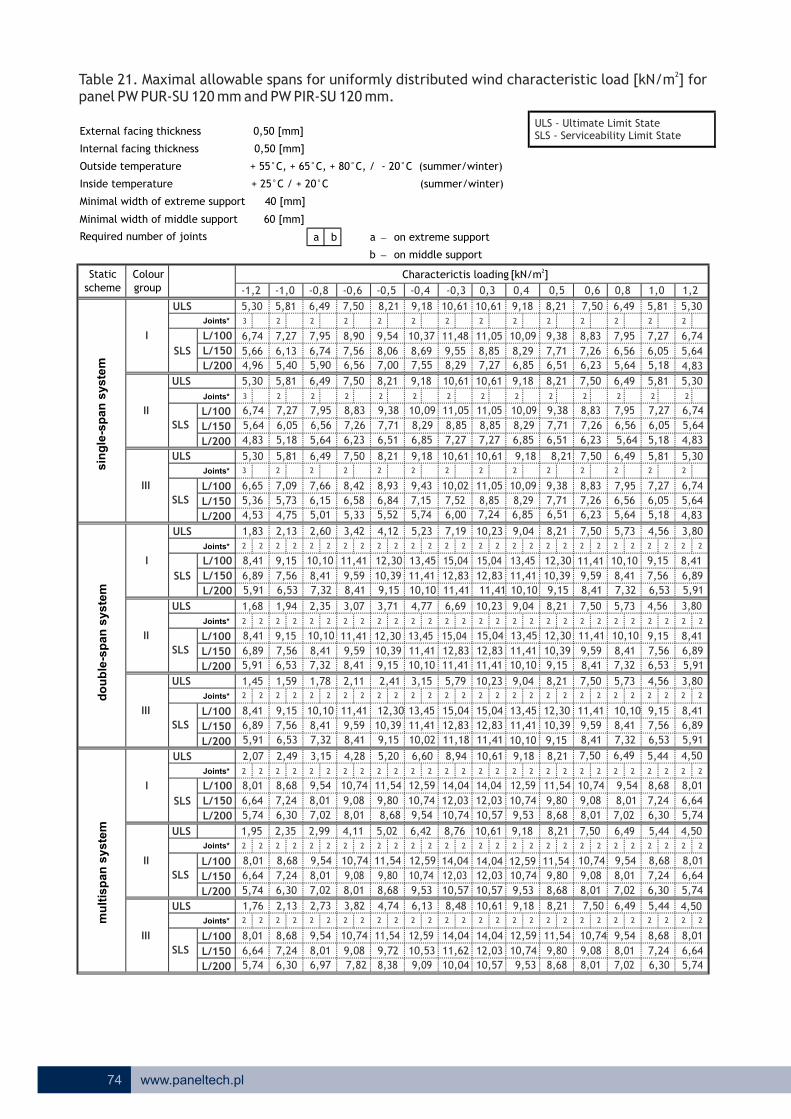
2Table 21. Maximal allowable spans for uniformly distributed wind characteristic load [kN/m ] for panel PW PUR-SU 120 mm and PW PIR-SU 120 mm.
ULS3 2 2 2 2 2 2 2 2 2 2 2 2 2
L/100
L/150
L/200
ULS
3 2 2 2 2 2 2 2 2 2 2 2 2 2
L/100
L/150
L/200
ULS3 2 2 2 2 2 2 2 2 2 2 2 2 2
L/100
L/150
L/200
2 2 2 2 2 2 2 2 2 2 2 2 2 2 2 2 2 2 2 2 2 2 2 2 2 2 2 2
2 2 2 2 2 2 2 2 2 2 2 2 2 2 2 2 2 2 2 2 2 2 2 2 2 2 2 2
2 2 2 2 2 2 2 2 2 2 2 2 2 2 2 2 2 2 2 2 2 2 2 2 2 2 2 2
2 2 2 2 2 2 2 2 2 2 2 2 2 2 2 2 2 2 2 2 2 2 2 2 2 2 2 2
2 2 2 2 2 2 2 2 2 2 2 2 2 2 2 2 2 2 2 2 2 2 2 2 2 2 2 2
2 2 2 2 2 2 2 2 2 2 2 2 2 2 2 2 2 2 2 2 2 2 2 2 2 2 2 2
6,85
5,30
6,74
-0,6
8,90
10,61
-0,5
11,0511,48
-0,4 -0,3
6,13
5,40
6,74
5,66
-1,0
5,81
7,27
-0,8
SLS
4,96
-1,2
5,30
SLS
6,64
5,74
I
II
III
SLS
5,91
1,45
8,41
8,76
10,74
12,03
14,04
5,91
2,07
8,01
5,64
4,83
5,30
6,65
5,36
1,68
6,89
1,83
8,41
6,89
5,91
8,41
6,89
1,95
8,01
6,64
5,74
1,76
8,01
6,64
5,74
5,81
7,27
6,05
5,18
5,81
7,09
5,73
7,56
6,53
1,59
2,13
9,15
7,56
1,94
9,15
9,15
7,56
6,53
2,49
8,68
7,24
6,30
2,35
8,68
7,24
6,30
2,13
8,68
7,24
6,30
6,49
7,95
6,74
5,90
6,49
7,95
6,56
5,64
6,49
7,66
6,15
8,41
2,60
10,10
8,41
2,35
10,10
7,32
1,78
10,10
8,41
7,32
3,15
6,97 7,82
3,82
8,01
9,54
8,01
7,02
2,99
9,54
8,01
9,08
10,74
7,02
2,73
9,54
8,01
11,54 12,59
6,13
11,62
4,74
8,38 9,09
10,539,72
10,04
14,04
9,08 9,80 10,74 12,03
9,53
8,48
10,578,68
14,0412,5911,5410,74
11,18
12,83
10,74
12,59
6,60
10,02
8,94
11,41
9,15
9,59
9,54
6,424,11
8,01 8,68
5,02
11,41
9,59
9,80
11,54
10,39
9,08
10,74
5,204,28
8,41
7,50
8,83
11,41 12,30
7,26
6,23
7,50
10,39
3,71
12,30
7,00
7,50
9,54
8,067,56
6,56
8,21
8,42
6,58
3,42
8,93
8,21
6,51
4,12
3,07
11,41
8,41
2,11 2,41
9,15
12,30
9,15
10,39
6,53
9,59
8,417,32
10,619,18
10,61
9,55
8,29
8,85
9,18 10,61
11,05
8,69
6,84
8,21
10,37
7,71
9,38
7,55
10,09
8,29
6,85
0,4 0,5 0,60,3 1,2
5,305,816,49
0,8
8,83
9,18
11,05 10,09
10,09
8,29
10,61
7,27
9,18
8,85
7,27
9,38
7,71
1,0
8,21 7,50
7,27
6,51
7,71
9,38
9,3810,0911,0510,02
8,21
10,61 9,18 8,21
6,516,857,27
8,298,85
9,43
7,15 7,52 8,85 8,29
15,04 15,04 13,45
7,19
12,30
7,71
4,77
12,83
11,41
6,69
8,219,0410,23
10,23
15,04
5,23
13,45
13,45 15,04
11,41
10,10 11,41
12,83
10,10
10,39
9,15
8,21
12,30
11,41
10,10
9,04
11,41
10,10
3,15
15,04
12,83
11,41
5,79
15,0413,45 12,30
12,83
13,45
12,83
11,41
10,23
10,39
9,15
8,21
11,41
9,04
10,61
13,45
11,41
10,10
9,18
10,39
14,04 12,59
12,03
9,1511,41
8,21
10,57
10,61
10,74
9,53
9,18 8,21
14,04
12,03
10,57
12,59
10,74
9,53
9,1810,61
14,04
12,03
10,57 9,53
10,74
12,59
5,74
6,649,089,80 8,01
8,68 7,028,01 6,30
8,01
4,50
7,24
8,68
5,44
9,54
6,49
11,54 10,74
8,21 7,50
5,74
6,64
8,01
7,02
8,01
9,54
6,30
7,24
8,68
4,50
6,64
5,74
8,018,68
8,68
9,80
8,01
9,08
10,7411,54
7,50 6,49 5,44
6,30
7,24
7,028,01
6,49
8,41
7,50
8,68
9,80
11,54
9,08 8,01
10,74 9,54
4,50
4,56
5,91
6,89
8,41
3,80
7,56
9,15
5,44
6,53
9,59
7,32
8,41
7,50
11,41 10,10
5,73
5,73
7,32
8,41
10,10
8,41 5,91
6,89
8,41
6,53
7,56
9,15
9,59
11,41
7,50
5,73
7,32
8,41
10,10
7,50
8,41
9,59
11,41
4,56
4,56 3,80
5,91
6,89
4,83
5,30
8,41
6,53
7,27
7,56
9,15
3,80
5,646,056,567,26
8,83
5,18
6,05
5,816,497,50
6,23 5,64
5,64
6,74
6,497,50
7,26
8,83 7,95
6,56
5,305,81
7,26
6,23
5,64
6,74
5,64
6,56
7,95
5,18
6,05
7,27
ULS
L/100
L/150
L/200
ULS
L/100
L/150
L/200
ULS
L/100
L/150
L/200
SLS
SLS
I
II
III
SLS
ULS
L/100
L/150
L/200
ULS
L/100
L/150
L/200
ULS
L/100
L/150
L/200
SLS
SLS
I
II
III
SLS
9,18
4,83
6,747,95
74 www.paneltech.pl
2Characterictis loading [kN/m ]scheme
Colour group
Static
do
ub
le-s
pan
syste
mm
ult
isp
an
syste
msin
gle
-sp
an
syste
m
Joints*
Joints*
Joints*
Joints*
Joints*
Joints*
Joints*
Joints*
Joints*
a b a - on extreme support
b - on middle support
Minimal width of extreme support 40 [mm]
Minimal width of middle support 60 [mm]
Internal facing thickness 0,50 [mm]
External facing thickness 0,50 [mm]
Required number of joints
Inside temperature + 25°C / + 20°C (summer/winter)
Outside temperature + 55°C, + 65°C, + 80°C, / - 20°C (summer/winter)
ULS - Ultimate Limit StateSLS - Serviceability Limit State
4,53 4,75 5,01 5,33 5,74 6,00 5,646,23 5,18 4,837,24 6,516,855,52

ULS
2 2 2 2 2 2 2 2 2 2 2 2 2 2
L/200
ULS
2 2 2 2 2 2 2 2 2 2 2 2 2 2
L/200
ULS
2 2 2 2 2 2 2 2 2 2 2 2 2 2
L/200
ULS
2 3 2 3 2 3 2 3 2 3 2 2 2 2 2 2 2 2 2 2 2 2 2 2 2 2 2 2
L/200
ULS
2 3 2 3 2 3 2 3 2 3 2 2 2 2 2 2 2 2 2 2 2 2 2 2 2 2 2 2
L/200
ULS
2 3 2 3 2 3 2 3 2 3 2 2 2 2 2 2 2 2 2 2 2 2 2 2 2 2 2 2
L/200
ULS
2 3 2 3 2 3 2 3 2 3 2 2 2 2 2 2 2 2 2 2 2 2 2 2 2 2 2 2
L/200
ULS
2 3 2 3 2 3 2 3 2 3 2 2 2 2 2 2 2 2 2 2 2 2 2 2 2 2 2 2
L/200
ULS
2 3 2 3 2 3 2 3 2 2 2 2 2 2 2 2 2 2 2 2 2 2 2 2 2 2 2 2
L/200
1,782,17 2,01
1,52
2,43 2,25
1,261,33
2,01
0,981,141,261,33
2,25 2,17 1,78
0,93
1,78
1,21
2,01
1,21 0,93
2,282,57
1,56
2,25
1,42
2,77
1,56
2,89
2,282,57
1,56 1,42
2,17
1,42
2,772,89
1,73
2,89
1,85
2,77
1,12
1,21
2,28
0,93
3,04
1,46
2,57
1,85 1,73 1,46
2,472,662,77
3,04 2,77
1,12
2,20
2,47
2,14
2,202,66
1,85 1,121,461,73
3,04 2,662,77 2,47 2,20
2,442,81
3,68 3,32
3,68 3,32
3,68
2,81
3,32
2,44 2,14
3,183,87
2,12
2,81
3,47
2,44 2,14
4,71
3,16
3,87
2,43
4,23
2,72
3,18
1,91
3,47
3,47
2,12
4,71 3,18
1,91
3,16
3,87
2,43
2,98
3,16
4,23
2,72
1,912,122,432,72
3,14 2,83 2,60 2,43
3,14
2,77 2,32
2,432,602,832,98
2,6
1,52 1,33
3,4
0,981,141,26
2,02
2,83
1,72 0,981,14
1,72
2,21,3 1,6 2,0
2,77 2,32 2,025,81
-0,4
4,24
0,6 0,8 1,0
3,14 2,98
3,94
6,71
4,61
4,92
3,24
3,33
5,45
3,00 4,12
6,71
3,54
3,03
5,45
3,94
3,60
5,61
3,94
4,35
-0,6
4,19
3,68
4,71
5,764,12
5,45 6,71 4,23
3,97
5,14 6,29
5,55
4,39
3,68
4,39
3,16
4,016,29
5,22 3,68
5,69 4,39 4,01
4,48
3,02
5,01
3,73
5,14
4,48
3,21
2,48
4,73
3,33
4,48
4,73
2,71
4,73
3,17
2,88
2,88
4,03
3,53
3,66
3,39
3,35
2,75
4,03
2,60
4,24
2,85
4,03
2,19
4,24
1,94
2,75
2,35
3,69
2,98
3,29
2,86
3,15
2,68
3,69
2,19
3,88
2,36
3,69
2,29
3,88
1,56
Joints*
Joints*
Joints*
2,99
2,33
2,64
1,77
3,16
4,01
3,16
1,90
3,88
Joints*
Joints*
Joints*
SLS
I
II
III
Joints*
I
II
III
SLS
Joints*
Joints*
SLS
-1,2 -1,0 -0,8
2,59
SLS
3,02
2,49
SLS
SLS
SLS
SLS
I
II
III
2,60SLS
2,32 2,02 1,72 1,522,775,293,94
2Table 22. Maximal allowable spans for uniformly distributed characteristic load [kN/m ] for panel PW PUR-D 40/82 .and PW PIR-D 40/82 mm
a b a - on extreme support
b - on middle support
Minimal width of extreme support 40 [mm]
Minimal width of middle support 60 [mm]
Internal facing thickness 0,50 [mm]
External facing thickness 0,50 [mm]
Required number of joints
Inside temperature + 25°C / + 20°C (summer/winter)
Outside temperature + 55°C, + 65°C, + 80°C, / - 20°C (summer/winter)
schemeColour group
2Characterictis loading [kN/m ]
do
ub
le-s
pan
syste
mm
ult
isp
an
syste
msin
gle
-sp
an
syste
m
Static
75www.paneltech.pl
ULS - Ultimate Limit StateSLS - Serviceability Limit State

ULS
2 2 2 2 2 2 2 2 2 2 2 2 2 2
L/200
ULS
2 2 2 2 2 2 2 2 2 2 2 2 2 2
L/200
ULS
2 2 2 2 2 2 2 2 2 2 2 2 2 2
L/200
ULS
2 3 2 3 2 3 2 3 2 3 2 2 2 2 2 2 2 2 2 2 2 2 2 2 2 2 2 2
L/200
ULS
2 3 2 3 2 3 2 3 2 3 2 2 2 2 2 2 2 2 2 2 2 2 2 2 2 2 2 2
L/200
ULS
2 3 2 3 2 3 2 3 2 3 2 2 2 2 2 2 2 2 2 2 2 2 2 2 2 2 2 2
L/200
ULS
2 3 2 3 2 3 2 3 2 3 2 2 2 2 2 2 2 2 2 2 2 2 2 2 2 2 2 2
L/200
ULS
2 3 2 3 2 3 2 3 2 3 2 2 2 2 2 2 2 2 2 2 2 2 2 2 2 2 2 2
L/200
ULS
2 3 2 3 2 3 2 3 2 3 2 2 2 2 2 2 2 2 2 2 2 2 2 2 2 2 2 2
L/200
3,16SLS
SLS
SLS
SLS
SLS
I
II
III
SLS
-1,2 -1,0 -0,8
3,44
SLS
3,71
3,32
I
II
III
I
II
III
SLS
SLS
3,38
4,86
3,38
1,85
4,70
3,71
3,14
3,25
1,68
4,70
1,45
4,70
2,31
4,50
2,22
4,50
2,07
4,50
3,99
4,06
3,86
3,94
3,66
3,40
2,27
2,07
5,17
1,76
5,17
2,85
4,93
2,75
4,93
2,59
4,93
4,74
4,53
4,59
4,21
4,37
3,58
2,95
5,80
2,71
5,80
2,31
5,80
3,64
5,50 6,35
4,13
6,35
5,50
3,49
5,50
3,27 3,97
7,32 5,36 4,86
5,36
3,38
4,867,84
6,03
4,43
6,35 7,84
6,45
5,36
3,97
5,10
3,97
5,70
6,724,62
6,73 8,36
5,84
-0,6
5,67
4,91
4,56
7,55
4,91
3,97
3,81
6,73
6,73
3,30 4,71
8,36
5,33
5,72
4,10
3,70
4,91
8,36
-0,4
5,17
0,6 0,8 1,0
3,85 3,65
3,05 2,597,65
2,21,3 1,6 2,0
3,71
3,4
1,071,271,43
2,59
3,44
2,12 1,071,27
2,12
2,6
1,81 1,53
2,933,163,443,653,85
3,71 3,05
3,85 3,44 3,16 2,93
2,92
3,65
3,41
5,10
2,92
2,002,242,583,41
4,65
2,58
4,15
2,24
5,70 3,77
2,00
5,10
2,92
3,77
2,00
4,155,70
3,41
4,65
2,58
3,774,65
2,24
2,97
4,15
2,56 2,27
4,45
2,97
3,98
2,56 2,27
4,45 3,98
2,562,97
4,45 3,98 3,64 3,143,28 2,90 2,54
1,241,631,902,27
2,543,14
2,01
1,24
2,54
2,903,64 3,28
2,01 1,90 1,63
2,903,143,283,64
1,63
2,99
1,24
1,35
2,61
1,05
1,90
3,39
2,01
3,24
1,75 1,59
2,59
1,59
3,243,39 2,612,99
1,75
3,39
1,75
2,69
1,59
3,24
1,35 1,05
2,612,99
1,05
2,09
1,35
2,39
1,53
2,69 2,59 2,092,39
1,071,271,43
1,431,53
2,39
1,81
2,93 2,69 2,092,59
5,42 7,25 3,05 2,59 2,12 1,813,71
2Table 23. Maximal allowable spans for uniformly distributed characteristic load [kN/m ] for panel PW PUR-D 60/102 .and PW PIR-D 60/120 mm
a b a - on extreme support
b - on middle support
Minimal width of extreme support 40 [mm]
Minimal width of middle support 60 [mm]
Internal facing thickness 0,50 [mm]
External facing thickness 0,50 [mm]
Required number of joints
Inside temperature + 25°C / + 20°C (summer/winter)
Outside temperature + 55°C, + 65°C, + 80°C, / - 20°C (summer/winter)
Joints*
Joints*
Joints*
Joints*
Joints*
Joints*
Joints*
Joints*
Joints*
schemeColour group
2Characterictis loading [kN/m ]
do
ub
le-s
pan
syste
mm
ult
isp
an
syste
msin
gle
-sp
an
syste
m
Static
76 www.paneltech.pl
ULS - Ultimate Limit StateSLS - Serviceability Limit State
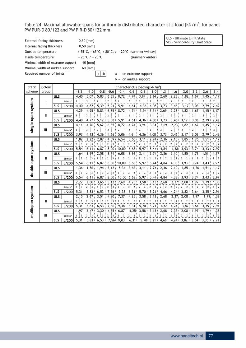
ULS
3 3 2 2 2 2 2 2 2 2 2 2 2 2
L/200
ULS
3 3 2 2 2 2 2 2 2 2 2 2 2 2
L/200
ULS
3 3 2 2 2 2 2 2 2 2 2 2 2 2
L/200
ULS
2 3 2 3 2 3 2 3 2 3 2 2 2 2 2 2 2 2 2 2 2 2 2 2 2 2 2 2
L/200
ULS
2 3 2 3 2 3 2 3 2 3 2 2 2 2 2 2 2 2 2 2 2 2 2 2 2 2 2 2
L/200
ULS
2 3 2 3 2 3 2 3 2 3 2 2 2 2 2 2 2 2 2 2 2 2 2 2 2 2 2 2
L/200
ULS
2 3 2 3 2 3 2 3 2 3 2 2 2 2 2 2 2 2 2 2 2 2 2 2 2 2 2 2
L/200
ULS
2 3 2 3 2 3 2 3 2 3 2 2 2 2 2 2 2 2 2 2 2 2 2 2 2 2 2 2
L/200
ULS
2 3 2 3 2 3 2 3 2 3 2 2 2 2 2 2 2 2 2 2 2 2 2 2 2 2 2 2
L/200
3,73SLS
SLS
SLS
SLS
SLS
I
II
III
SLS
-1,2 -1,0 -0,8
4,40
SLS
4,40
4,29
I
II
III
I
II
III
SLS
SLS
3,58
5,70
3,58
1,82
5,54
4,40
4,11
3,93
1,64
5,54
1,36
5,54
2,27
5,31
2,15
5,31
1,97
5,31
5,07
4,82
4,95
4,77
4,76
4,13
2,22
1,99
6,11
1,56
6,11
2,80
5,83
2,67
5,83
2,47
5,83
5,83
5,39
5,83
5,12
5,62
4,36
2,87
6,87
2,58
6,87
1,94
6,87
3,65
6,53 7,56
4,55
7,56
6,53
3,51
6,53
3,30 4,25
9,03 6,31 5,70
6,31
3,58
5,709,38
6,87
4,90
7,56 9,38
7,37
6,31
4,25
5,97
4,25
6,68
7,695,12
8,00 10,00
6,85
-0,6
6,85
5,91
5,58
6,85
8,72
5,91
4,09
4,66
8,00
8,00
3,12 5,34
10,00
6,08
6,54
5,06
3,74
8,72
5,91
10,00
-0,4
6,11
0,6 0,8 1,0
4,61 4,36
3,94 3,348,72
2,21,3 1,6 2,0
4,74
3,4
1,171,451,67
3,34
4,08
2,69 1,171,45
2,69
2,6
2,23 1,82
3,463,734,084,36
3,94 3,34 2,69 2,234,74
4,61
4,74 3,94
4,61 4,08 3,73 3,46
3,11
4,36
3,66
5,97
3,11
2,102,362,743,66
5,44
2,74
4,84
2,36
6,68 4,38
2,10
5,97
3,11
4,38
2,10
4,846,68
3,66
5,44
2,74
4,385,44
2,36
3,13
4,84
2,68 2,37
5,21
3,13
4,66
2,68 2,37
5,21 4,66
2,683,13
5,21 4,66 4,24 3,643,82 3,35 2,91
1,381,791,972,37
2,913,64
2,08
1,38
2,91
3,354,24 3,82
2,08 1,97 1,79
3,353,643,824,24
1,79
3,43
1,38
1,51
2,97
1,17
1,97
3,93
2,08
3,74
1,85 1,76
3,03
1,76
3,743,93 2,973,43
1,85
3,93
1,85
3,17
1,76
3,74
1,51 1,17
2,973,43
1,17
2,42
1,51
2,79
1,82
3,17 3,03 2,422,79
1,171,451,67
1,671,82
2,79
2,23
3,46 3,17 2,423,03
2Table 24. Maximal allowable spans for uniformly distributed characteristic load [kN/m ] for panel PW PUR-D 80/122 . and PW PIR-D 80/122 mm
a b a - on extreme support
b - on middle support
Minimal width of extreme support 40 [mm]
Minimal width of middle support 60 [mm]
Internal facing thickness 0,50 [mm]
External facing thickness 0,50 [mm]
Required number of joints
Inside temperature + 25°C / + 20°C (summer/winter)
Outside temperature + 55°C, + 65°C, + 80°C, / - 20°C (summer/winter)
Joints*
Joints*
Joints*
Joints*
Joints*
Joints*
Joints*
Joints*
Joints*
schemeColour group
2Characterictis loading [kN/m ]
do
ub
le-s
pan
syste
mm
ult
isp
an
syste
msin
gle
-sp
an
syste
m
Static
77www.paneltech.pl
ULS - Ultimate Limit StateSLS - Serviceability Limit State

ULS
3 3 3 2 2 2 2 2 2 2 2 2 2 2
L/200
ULS
3 3 3 2 2 2 2 2 2 2 2 2 2 2
L/200
ULS
3 3 3 2 2 2 2 2 2 2 2 2 2 2
L/200
ULS
2 3 2 3 2 3 2 3 2 3 2 2 2 2 2 2 2 2 2 2 2 2 2 2 2 2 2 2
L/200
ULS
2 3 2 3 2 3 2 3 2 3 2 2 2 2 2 2 2 2 2 2 2 2 2 2 2 2 2 2
L/200
ULS
2 3 2 3 2 3 2 3 2 3 2 2 2 2 2 2 2 2 2 3 2 3 2 3 2 3 2 2
L/200
ULS
2 3 2 3 2 3 2 3 2 3 2 2 2 2 2 2 2 2 2 2 2 2 2 2 2 2 2 2
L/200
ULS
2 3 2 3 2 3 2 3 2 3 2 2 2 2 2 2 2 2 2 2 2 2 2 2 2 2 2 2
L/200
ULS
2 3 2 3 2 3 2 3 2 3 2 2 2 2 2 2 2 2 2 2 2 2 2 2 2 2 2 2
L/200
4,02
1,0 3,4
1,24
SLS 4,74
I
SLS
-1,2 -1,0 -0,8
4,88
SLS
SLS
SLS
SLS
II
III
II
III
SLS
SLS
I
SLS
4,77
I
II
III
3,68
6,11
3,68
1,80
5,96
4,74
4,60
4,28
1,62
5,96
2,25
5,96
1,31
5,71
1,92
5,71
2,12
5,71
5,45
5,20
5,45
5,20
5,29
1,96
4,50
2,20
6,58
2,78
6,58
1,48
6,28
2,41
6,28
2,64
6,28
6,15
5,81
6,15
5,58
2,83
7,41
6,15
4,77
1,77
7,41
2,53
7,41
3,63
7,04 8,16
4,76
8,16
7,04
3,48
4,387,32
7,04
3,24
9,89 6,78 6,11
6,78
3,68
6,1110,15
5,01
8,16 10,15
7,85 4,38
6,40
4,38
7,16
6,78
8,205,16
8,64 10,82
7,23
-0,6
7,23
6,40
6,09
9,23
6,40
4,05
5,10 5,56
6,40
8,64
2,70 5,67
10,82
8,64
3,65 6,47
6,97
10,826,58
0,6 0,8
4,98 4,71
4,39 3,749,23
2,21,3 1,6 2,0
5,24
-0,4
3,74
4,39
3,02
3,413,72
1,561,83
2,6
2,50 2,01
2,99
1,56
3,02
3,724,024,394,71
2,50
4,98
3,72
5,24 4,39 2,50
4,98 4,39 4,02
2,152,422,823,213,78
4,71
3,78
6,407,16 5,83
2,823,21
5,18
4,69
2,15
5,18
2,42
7,16
3,78
6,40
3,21
5,83
2,82
4,69
2,15
5,83
2,42
3,21
5,18
2,74
5,59
3,21
4,99
2,74
4,69
2,41
5,59 4,99
5,59 4,99
2,743,21
4,54 3,894,08
1,441,82
3,103,58
2,002,41 2,11
3,103,89 3,58
2,11 2,00 1,82 1,44
3,10
4,54 4,08
4,54
1,82
3,66
3,583,894,08
2,41 2,002,11 1,44
1,59
3,16
1,24
4,00
1,89 1,79
4,20
3,26
1,79
4,00
1,89
4,20
4,20 3,163,66
1,59 1,24
3,16
1,89
3,41
1,79
4,00 3,66
1,24
2,59
1,59
2,99
2,01
3,41 3,26 2,59
1,24
2,99
1,561,83
1,832,01 1,24
2,593,26
7,23 9,23 5,24 4,39 3,74 3,02
2Table 25. Maximal allowable spans for uniformly distributed characteristic load [kN/m ] for panel PW PUR-D 90/132 . and PW PIR-D 90/132 mm
a b a - on extreme support
b - on middle support
Minimal width of extreme support 40 [mm]
Minimal width of middle support 60 [mm]
Internal facing thickness 0,50 [mm]
External facing thickness 0,50 [mm]
Required number of joints
Inside temperature + 25°C / + 20°C (summer/winter)
Outside temperature + 55°C, + 65°C, + 80°C, / - 20°C (summer/winter)
Joints*
Joints*
Joints*
Joints*
Joints*
Joints*
Joints*
Joints*
Joints*
schemeColour group
2Characterictis loading [kN/m ]
do
ub
le-s
pan
syste
mm
ult
isp
an
syste
msin
gle
-sp
an
syste
m
Static
78 www.paneltech.pl
ULS - Ultimate Limit StateSLS - Serviceability Limit State

ULS
3 3 3 2 2 2 2 2 2 2 2 2 2 2
L/200
ULS
3 3 3 2 2 2 2 2 2 2 2 2 2 2
L/200
ULS
3 3 3 2 2 2 2 2 2 2 2 2 2 2
L/200
ULS
2 3 2 3 2 3 2 3 2 3 2 2 2 2 2 2 2 2 2 2 2 2 2 2 2 2 2 2
L/200
ULS
2 3 2 3 2 3 2 3 2 3 2 2 2 2 2 2 2 2 2 2 2 2 2 2 2 2 2 2
L/200
ULS
2 3 2 3 2 3 2 3 2 3 2 2 2 2 2 2 2 3 2 3 2 3 2 3 2 3 2 2
L/200
ULS
2 3 2 3 2 3 2 3 2 3 2 2 2 2 2 2 2 2 2 2 2 2 2 2 2 2 2 2
L/200
ULS
2 3 2 3 2 3 2 3 2 3 2 2 2 2 2 2 2 2 2 2 2 2 2 2 2 2 2 2
L/200
ULS
2 3 2 3 2 3 2 3 2 3 2 2 2 2 2 2 2 2 2 2 2 2 2 2 2 2 2 2
L/200
4,30SLS
SLS
SLS
SLS
SLS
I
II
III
SLS
-1,2 -1,0 -0,8
5,18
SLS
5,08
5,18
I
II
III
I
II
III
SLS
SLS
3,78
6,52
3,78
1,79
6,38
5,08
5,07
4,63
1,61
6,38
1,28
6,38
2,23
6,11
2,10
6,11
1,88
6,11
5,71
5,57
5,71
5,57
5,71
4,87
2,18
1,94
7,04
1,43
7,04
2,76
6,72
2,61
6,72
2,36
6,72
6,46
6,22
6,46
6,04
6,46
5,17
2,80
7,93
2,48
7,93
1,66
7,93
3,61
7,53 8,74
4,70
8,74
7,53
3,44
7,53
3,17 4,50
10,75 7,24 6,52
7,24
3,78
6,5210,89
7,74
4,98
8,74 10,89
8,32
7,24
4,50
6,82
4,50
7,63
8,695,15
9,25 11,61
7,60
-0,6
7,60
6,89
6,60
9,72
6,89
4,00
5,55
9,25
9,25
2,16 5,61
11,61
6,49
6,98
6,06
3,57
6,89
11,61
-0,4
7,04
0,6 0,8 1,0
5,35 5,05
4,82 4,149,72
2,21,3 1,6 2,0
5,73
3,4
1,311,702,02
4,14
4,71
3,37 1,311,70
3,37
2,6
2,79 2,23
3,994,304,715,055,35
5,73 4,82
5,35 4,71 4,30 3,99
3,30
5,05
3,90
6,82
3,30
2,202,482,893,90
6,21
2,89
5,52
2,48
7,63 5,00
2,20
6,82
3,30
5,00
2,20
5,527,63
3,90
6,21
2,89
5,006,21
2,48
3,29
5,52
2,80 2,46
5,96
3,29
5,32
2,80 2,46
5,96 5,32
2,803,29
5,96 5,32 4,84 4,154,35 3,81 3,30
1,471,842,032,46
3,304,15
2,15
1,47
3,30
3,814,84 4,35
2,15 2,03 1,84
3,814,154,354,84
1,84
3,89
1,47
1,63
3,35
1,27
2,03
4,47
2,15
4,25
1,93 1,83
3,48
1,83
4,254,47 3,353,89
1,93
4,47
1,93
3,65
1,83
4,25
1,63 1,27
3,353,89
1,27
2,77
1,63
3,20
2,23
3,65 3,48 2,773,20
1,311,702,02
2,022,23
3,20
2,79
3,99 3,65 2,773,48
7,60 9,72 4,82 4,14 3,37 2,795,73
2Table 26. Maximal allowable spans for uniformly distributed characteristic load [kN/m ] for panel PW PUR-D 100/142 . and PW PIR-D 100/142 mm
a b a - on extreme support
b - on middle support
Minimal width of extreme support 40 [mm]
Minimal width of middle support 60 [mm]
Internal facing thickness 0,50 [mm]
External facing thickness 0,50 [mm]
Required number of joints
Inside temperature + 25°C / + 20°C (summer/winter)
Outside temperature + 55°C, + 65°C, + 80°C, / - 20°C (summer/winter)
Joints*
Joints*
Joints*
Joints*
Joints*
Joints*
Joints*
Joints*
Joints*
schemeColour group
2Characterictis loading [kN/m ]
do
ub
le-s
pan
syste
mm
ult
isp
an
syste
msin
gle
-sp
an
syste
m
Static
79www.paneltech.pl
ULS - Ultimate Limit StateSLS - Serviceability Limit State

ULS
3 3 3 3 2 2 2 2 2 2 2 2 2 2
L/200
ULS
3 3 3 3 2 2 2 2 2 2 2 2 2 2
L/200
ULS
3 3 3 3 2 2 2 2 2 2 2 2 2 2
L/200
ULS
2 3 2 3 2 3 2 3 2 3 2 2 2 2 2 2 2 2 2 2 2 2 2 2 2 2 2 2
L/200
ULS
2 3 2 3 2 3 2 3 2 3 2 2 2 2 2 2 2 2 2 2 2 2 2 2 2 2 2 2
L/200
ULS
2 3 2 3 2 3 2 3 2 3 2 2 2 2 2 3 2 3 2 3 2 3 2 3 2 3 2 2
L/200
ULS
2 3 2 3 2 3 2 3 2 3 2 2 2 2 2 2 2 2 2 2 2 2 2 2 2 2 2 2
L/200
ULS
2 3 2 3 2 3 2 3 2 3 2 2 2 2 2 2 2 2 2 2 2 2 2 2 2 2 2 2
L/200
ULS
2 3 2 3 2 3 2 3 2 3 2 2 2 2 2 2 2 2 2 2 2 2 2 2 2 2 2 2
L/200
3,123,92 3,60
3,41
4,51 4,11
2,472,74
3,60
1,502,032,472,74
4,11 3,92 3,12
1,26
3,12
1,62
3,60
1,62 1,26
3,744,35
2,01
4,11
1,89
4,76
2,01
5,01
3,744,35
2,01 1,89
3,92
1,89
4,765,01
2,10
5,01
2,22
4,76
1,46
1,62
3,74
1,26
5,43
1,89
4,35
2,22 2,10 1,89
4,264,654,88
5,43 4,88
1,46
3,68
4,26
2,56
3,684,65
2,22 1,461,892,10
5,43 4,654,88 4,26 3,68
2,913,44
6,68 5,97
6,68 5,97
6,68
3,44
5,97
2,91 2,56
5,616,96
2,60
3,44
6,19
2,91 2,56
8,53
4,12
6,96
3,04
7,64
3,48
5,61
2,29
6,19
6,19
2,60
8,53 5,61
2,29
4,12
6,96
3,04
5,70
4,12
7,64
3,48
2,292,603,043,48
6,08 5,31 4,86 4,51
6,08
6,64 5,65
4,514,865,315,70
2,6
3,41 2,74
3,4
1,502,032,47
4,91
5,31
4,06 1,502,03
4,06
2,21,3 1,6 2,0
6,64 5,65 4,9110,66
-0,4
7,95
0,6 0,8 1,0
6,08 5,70
7,82
13,21
6,32
6,92
7,08
3,42
10,48
1,83 5,16
13,21
3,91
6,44
10,48
7,82
7,63
10,66
7,82
8,31
-0,6
8,31
4,74
8,53
8,795,13
10,48 13,21 7,64
4,93
9,89 12,16
8,58
8,11
4,74
8,11
3,97
7,2912,16
8,26 4,74
12,16 8,11 7,29
8,51
3,05
9,89
4,59
9,89
8,51
3,37
1,54
8,97
3,57
8,51
8,97
2,41
8,97
7,04
5,98
2,75
7,59
7,04
7,03
7,04
6,95
2,55
7,59
2,26
7,95
2,72
7,59
1,90
7,95
1,37
5,63
2,16
6,90
6,22
6,29
6,22
6,29
6,22
6,90
1,81
7,20
2,20
6,90
2,05
7,20
1,24
5,74
5,64
5,34
1,59
3,97
7,29
3,97
1,78
7,20
SLS
I
II
III
I
II
III
SLS
SLS
-1,2 -1,0 -0,8
5,64
SLS
5,74
5,64
SLS
SLS
SLS
SLS
I
II
III
4,86SLS
6,64 5,65 4,91 4,06 3,4110,668,31
Table 27. and PW PIR-D 120/162 mm
2 Maximal allowable spans for uniformly distributed characteristic load [kN/m ] for panel
PW PUR-D 120/162 .
a b a - on extreme support
b - on middle support
Minimal width of extreme support 40 [mm]
Minimal width of middle support 60 [mm]
Internal facing thickness 0,50 [mm]
External facing thickness 0,50 [mm]
Required number of joints
Inside temperature + 25°C / + 20°C (summer/winter)
Outside temperature + 55°C, + 65°C, + 80°C, / - 20°C (summer/winter)
Joints*
Joints*
Joints*
Joints*
Joints*
Joints*
Joints*
Joints*
Joints*
schemeColour group
2Characterictis loading [kN/m ]
do
ub
le-s
pan
syste
mm
ult
isp
an
syste
msin
gle
-sp
an
syste
m
Static
80 www.paneltech.pl
ULS - Ultimate Limit StateSLS - Serviceability Limit State
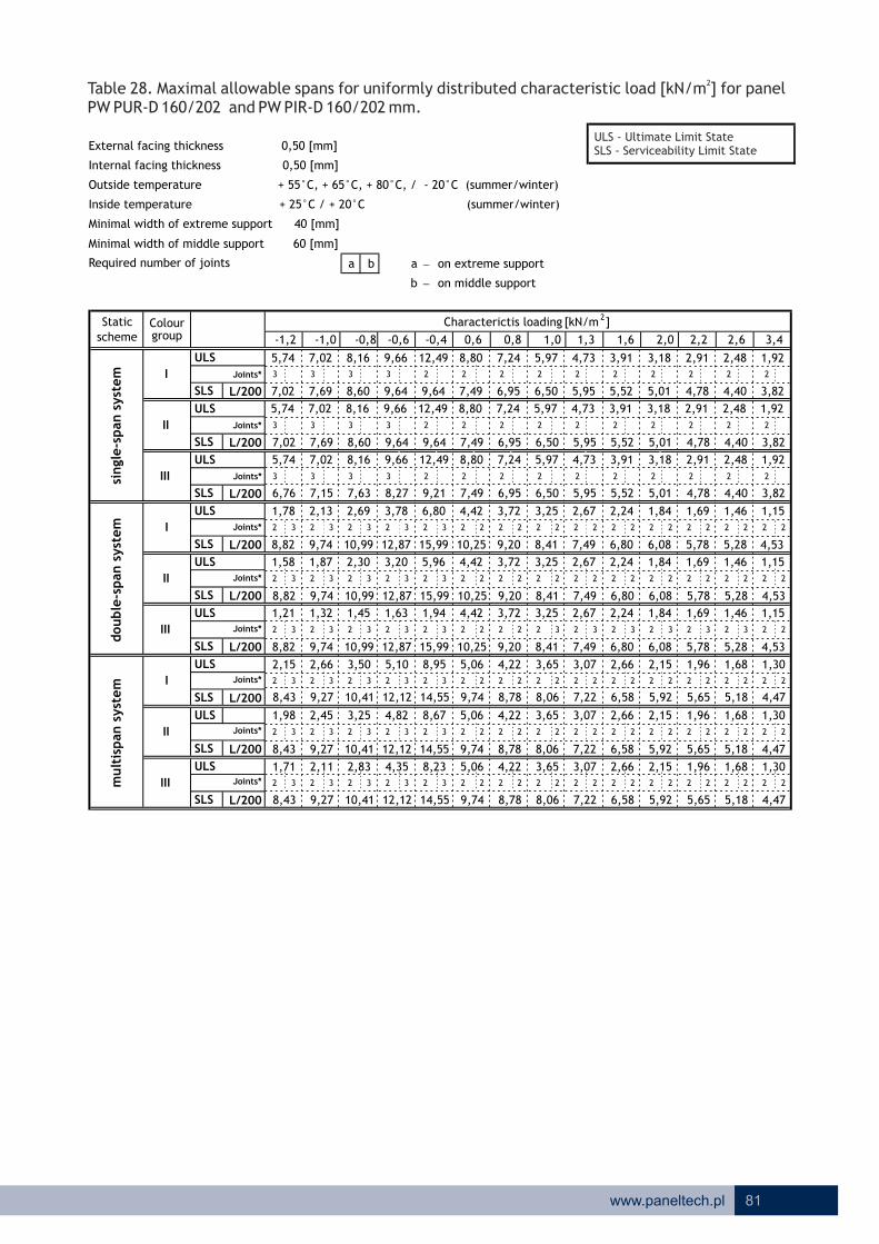
Table 2 . and PW PIR-D 160/202 mm
28 Maximal allowable spans for uniformly distributed characteristic load [kN/m ] for panel
PW PUR-D 160/202 .
a b a - on extreme support
b - on middle support
Minimal width of extreme support 40 [mm]
Minimal width of middle support 60 [mm]
Internal facing thickness 0,50 [mm]
External facing thickness 0,50 [mm]
Required number of joints
Inside temperature + 25°C / + 20°C (summer/winter)
Outside temperature + 55°C, + 65°C, + 80°C, / - 20°C (summer/winter)
81www.paneltech.pl
ULS
3 3 3 3 2 2 2 2 2 2 2 2 2 2
L/200
ULS
3 3 3 3 2 2 2 2 2 2 2 2 2 2
L/200
ULS
3 3 3 3 2 2 2 2 2 2 2 2 2 2
L/200
ULS
2 3 2 3 2 3 2 3 2 3 2 2 2 2 2 2 2 2 2 2 2 2 2 2 2 2 2 2
L/200
ULS
2 3 2 3 2 3 2 3 2 3 2 2 2 2 2 2 2 2 2 2 2 2 2 2 2 2 2 2
L/200
ULS
2 3 2 3 2 3 2 3 2 3 2 2 2 2 2 3 2 3 2 3 2 3 2 3 2 3 2 2
L/200
ULS
2 3 2 3 2 3 2 3 2 3 2 2 2 2 2 2 2 2 2 2 2 2 2 2 2 2 2 2
L/200
ULS
2 3 2 3 2 3 2 3 2 3 2 2 2 2 2 2 2 2 2 2 2 2 2 2 2 2 2 2
L/200
ULS
2 3 2 3 2 3 2 3 2 3 2 2 2 2 2 2 2 2 2 2 2 2 2 2 2 2 2 2
L/200
2,6 3,42,21,3 1,6 2,0-0,4 0,6 0,8 1,0-0,6
Colour
SLS
I
II
III
I
II
III
SLS
SLS
-1,2 -1,0 -0,8
SLS
SLS
SLS
Characterictis loading [kN/m2]
SLS
SLS
I
II
III
SLS
5,74 7,02 8,16 9,66 12,49 8,80 7,24 5,97 4,73 3,91 3,18 2,91 2,48 1,92
7,02 7,69 8,60 9,64 9,64 7,49 6,95 6,50 5,95 5,52 5,01 4,78 4,40 3,82
5,74 7,02 8,16 9,66 12,49 8,80 7,24 5,97 4,73 3,91 3,18 2,91 2,48 1,92
7,02 7,69 8,60 9,64 9,64 7,49 6,95 6,50 5,95 5,52 5,01 4,78 4,40 3,82
5,74 7,02 8,16 9,66 12,49 8,80 7,24 5,97 4,73 3,91 3,18 2,91 2,48 1,92
6,76 7,15 7,63 8,27 9,21 7,49 6,95 6,50 5,95 5,52 5,01 4,78 4,40 3,82
1,78 2,13 2,69 3,78 6,80 4,42 3,72 3,25 2,67 2,24 1,84 1,69 1,46 1,15
8,82 9,74 10,99 12,87 15,99 10,25 9,20 8,41 7,49 6,80 6,08 5,78 5,28 4,53
1,58 1,87 2,30 3,20 5,96 4,42 3,72 3,25 2,67 2,24 1,84 1,69 1,46 1,15
8,82 9,74 10,99 12,87 15,99 10,25 9,20 8,41 7,49 6,80 6,08 5,78 5,28 4,53
1,21 1,32 1,45 1,63 1,94 4,42 3,72 3,25 2,67 2,24 1,84 1,69 1,46 1,15
8,82 9,74 10,99 12,87 15,99 10,25 9,20 8,41 7,49 6,80 6,08 5,78 5,28 4,53
2,15 2,66 3,50 5,10 8,95 5,06 4,22 3,65 3,07 2,66 2,15 1,96 1,68 1,30
8,43 9,27 10,41 12,12 14,55 9,74 8,78 8,06 7,22 6,58 5,92 5,65 5,18 4,47
1,98 2,45 3,25 4,82 8,67 5,06 4,22 3,65 3,07 2,66 2,15 1,96 1,68 1,30
8,43 9,27 10,41 12,12 14,55 9,74 8,78 8,06 7,22 6,58 5,92 5,65 5,18 4,47
1,71 2,11 2,83 4,35 8,23 5,06 4,22 3,65 3,07 2,66 2,15 1,96 1,68 1,30
8,43 9,27 10,41 12,12 14,55 9,74 8,78 8,06 7,22 6,58 5,92 5,65 5,18 4,47
group
double
-span s
yst
em
mult
ispan s
yst
em
single
-span s
yst
em
scheme
Static
Joints*
Joints*
Joints*
Joints*
Joints*
Joints*
Joints*
Joints*
Joints*
ULS - Ultimate Limit StateSLS - Serviceability Limit State

NOTES
82 www.paneltech.pl

M O D E R N B U I L D I N G