silva,goldenstein,sousa e de mello2007 - pmtpmt.usp.br/academic/hgoldens/silva,goldenstein,sousa e...
TRANSCRIPT

1
Room Temperature Mechanical Properties and Tribology of Nicralc and Stellite as Cast Alloys. Silva, W. S.1; Souza, R.M.2; Mello, J.D.B3; Goldenstein*, H. 1
1Universidade de São Paulo, Escola Politécnica, PMT – [email protected]. 2Universidade de São Paulo, Escola Politécnica, PME.
3Universidade Federal de Uberlândia, Faculdade de Engenharia Mecânica. Abstract NICRALC is a family of intermetallic compound-based casting alloys proposed as a substitute for abrasion and erosion-resistant cobalt alloys. NICRALC microstructures contain hard chromium carbides dispersed in a continuous Ni-Al-Cr γ' (L12) ordered intermetallic matrix. Five as-cast NICRALC alloys with different carbon contents, different carbide types and morphological features were compared with Stellite 6 alloy and high-chromium-white-cast-iron (HCWCI), with regard to their mechanical and tribological behaviour at room temperature. Mechanical properties were evaluated by measurements of compression, hardness and fracture toughness; tribological properties were evaluated by sand-rubber-wheel wear, reciprocating sliding wear, block-on-ring lubricated sliding wear and erosion wear tests at room temperature. Yield stress, hardness and fracture toughness of NICRALC alloys were found to be dependent upon carbon content. However, their wear behaviour was found not to be directly related to hardness, yield stress and fracture toughness, but instead dependent upon the type and distribution of carbides. Eutectic NICRALC alloys demonstrated wear resistances similar to those shown for STELLITE. Introduction The NICRALC family of foundry alloys combines a some characteristics of Ni-based superalloys with features found in high-chromium-white-cast-irons (HCWCI); associating the anomalous behaviour of the ordered intermetallic phase Ni3Al (γ’) (which increases in strength following increases in temperature) with a dispersion of hard chromium carbides [1, 2, 3, 4]. The motivation of the development of the NICRALC alloys is the search for an alternative to iron-based wear resistant alloys at temperatures where they loose significantly their strength, as well as to search a substitute for cobalt-based high temperature wear resistant alloys. The mechanical strength of intermetallic Ni3Al can be improved by the addition of hard phases [5]. Bullock et al. [6], studying Ni-Ni3Al-Cr3C2 in situ directionally solidified composites, found that the composite presented better creep resistance than the matrix-only material. Nemoto et al. [7], studying polycrystalline Ni3(Al,Cr) alloys with low carbon content, observed fine dispersions of M23C6 carbides after solution annealing and aging treatments and these carbides increased the yield strength at high temperatures. As-cast alloys developed following the NICRALC concept have been explored with regard to their microstructures and solidification sequence [2, 3, 4], thermodynamic modeling of the equilibrium phases [2, 3, 8], castability [4, 9] and mechanical behavior at different temperatures [4, 10]. Simultaneously, the tribology of spray-formed NICRALC alloys was studied [11] using the pin-on-disc test method at room temperature.
With regard to mechanical behavior of NICRALC alloys, previous works show that room temperature yield strength is directly related to carbon content [4, 10]. Mechanical tests at different temperatures showed an increase in yield strength up to temperatures between 600 and 800°C. The maximum strength also increased with increasing carbon contents. The temperatures where maximum strength were found decreases with the carbon content. Cast irons and STELLITE materials, however, always demonstrated decreases in yield strength with increasing temperature [4, 10].

2
Ni-based alloys have applications in various complex engineering systems, yet there is little published data regarding the wear behaviour of these alloys. At room temperature, it was not possible to establish some correlation between mechanical properties and the erosion resistance [12]. In this case, the erosion wear of different materials of similar hardness can be correlated to the strain hardening behaviour. Experiments with nickel-aluminide plasma spray coatings deposited over a Fe-based superalloy showed that the impact erosion rate, measured at room temperature and at velocity of 40 m/s, was determined by the ductile behavior of the coating, characterized by “platelet and lips mechanisms” [13]. On the other hand, single impacts at high velocity (~300 m/s) caused a brittle response in thermally sprayed Cr3C2–NiCr coatings, with both the carbide grains and matrix being cleaved by the erodent particle [14]. Heat treatment of the coating significantly reduced this erosion rate, meaning that the ductility of the alloys controls the erosion rate of the coatings under high velocity tests. High temperature intermediate velocity erosion tests using the same materials studied in this paper showed that NICRALC alloys were more wear resistant than STELLITE and HCWCI at high temperatures [4]. Cavitation erosion experiments run at room temperature showed that the damage in NICRALC alloys was concentrated in the disordered phase of the matrix, while in STELLITE alloys the damage was concentrated at the interface between the matrix and Cr carbides [4]. The literature shows that the cavitation and erosion resistance of STELLITE is related to a strain hardening behavior of the Co matrix due to either twinning or strain-induced-shear phase transformation from FCC to HC martensite [15].
Pin-on-disk abrasion wear tests using SiC sandpaper disks of various abrasive grain sizes showed that spray-formed NICRALC and as-cast NICRALC alloys showed wear resistance similar to or better than as-cast HCWCI, despite their considerably lower hardness [11]. NICRALC alloys have a hardness of 550 HV, while HCWCI has a hardness of 650 HV. The behaviour of NICRALC varied with carbon content, carbides volume fraction and size, and, consequently with the hardness as well [11].
The sliding wear characteristics of superalloys and STELLITE are usually explained by two main mechanisms [16]: (i) “oxidative wear”, in which the rate of wear is controlled by the kinetics of oxidation as well as the thermomechanical properties of the oxides formed in conditions of mild wear; ii) nucleation and propagation of cracks followed by chip removal during severe wear. Other authors suggest that oxide film spalling is essentially a fatigue process, implying that there are critical temperatures and contact loads above which the wear becomes severe, and oxidation is no longer the controlling factor [17]. In the case of room temperature lubricated wear, the process is controlled by contact characteristics, which depend upon surface roughness, fluid viscosity, contact loads as well as the microstructure, mechanical properties and the relative speed of the bodies in contact [18]. Some results of the literature show relations between fracture toughness and the wear resistance. The abrasive wear of heat-treated steels is dependent on the size of abrasive particle and the mode II fracture toughness of the wear surface. The wear rate becomes significant for low fracture toughness values [19]. The sliding wear resistance of high-speed steel (HSS) is determined by the substructure, the morphology, and the size and the type of carbides, all of which influence the initiation and propagation of cracks [20]. The new wear resistant metal matrix composites produced by powder metallurgy developed to present a bimodal dispersion of hard particles shows an improved fracture toughness while maintaining a high level of wear resistance without the need to decrease the mechanical strength [21]. The results obtained from spray formed NICRALC alloys tested with a pin-on-disc abrasion test showed that mass loss decreases with increases in hardness [11], except for the material with the highest carbide volume fraction, more refined carbide distribution and hardness. This exception can be determined by the expected lower fracture toughness of this alloy. Experimental Details

3
Materials This work aims to characterize the mechanical properties and the wear resistance of NICRALC alloys, with different carbon contents, different amounts of carbides and different as-cast microstructures, evaluated at room temperature. The work will also compare these obtained results to those measured for conventional, industrial grade materials, including as-cast Co-based STELLITE 6 alloy and HCWCI, with a view toward replacing STELLITE as a non-magnetic bearing material, used for submerged pumps used in oil extraction. The NICRALC alloys, STELLITE and HCWCI were investigated by erosion, abrasion, sliding (dry reciprocating and lubricated FALEX test), compression, indentation and chevron notched fracture toughness mechanics tests.
The NICRALC alloys used in this work were designed using computational thermodynamic tools developed previously [2, 3, 8]. The alloys studied were cast with different levels of carbon content so as to obtain hypoeutectic, eutectic and hypereutectic as-cast alloys, each containing Cr carbides (M7C3 and/or M3C2) distributed in a predominantly γ’ (Ni3Al) matrix. Table 1 presents the chemical composition of the analyzed materials in this work. NICRALC alloys C1, 05, 07, 10 and 13 as well as STELLITE 6 were obtained by investment casting under a flow of Argon in an open induction furnace [9], while NICRALC OSP was spray-formed after being melted under an Argon atmosphere [11]. Raw materials used include electrolytic Ni, commercial Al, electrolytic Cr and graphite. Boron was added using Al-4.3%B as a master alloy. Pouring was effected at 1550°C. The HCWCI was produced by conventional sand casting. NICRALC alloys 05, 07, 10 and 13 were tested after solution annealing at 1200°C for 24 h followed by aging heat treatment at 760°C for 24 h. NICRALC C1, NICRALC OSP and STELLITE were tested in as-cast condition. HCWCI was solution hardened at 950°C for 30 minutes and twice tempered at 550°C for 1 hour. Table 1 – Chemical Composition of Studied Alloys.
Weight % Material C Ni Cr Al B Si Fe Others
NICRALC C1 0.840 Bal 12.180 7.630 - 2.290 1.44 - NICRALC 05 0.565 Bal 7.097 10.081 0.014 0.030 - Mn=0.040 NICRALC 07 0.666 Bal 11.075 9.207 0.039 0.045 - Mn=0.040 NICRALC 10 0.860 Bal 12.012 8.547 0.019 0.052 - Mn=0.045 NICRALC 13 1.312 Bal 11.100 9.284 0.045 0.047 - Mn=0.040
NICRALC OSP 0.500 Bal 8.000 9.440 0.060 - - - STELLITE 6 1.200 3.0 30.000 - - 2.000 3.00 Co=Bal; W=4.5; Mo=1.5; Mn=2.0
HCWCI 2.620 1.25 16.320 - - 0.450 Bal Mn=1.03; Mo=1.19; Nb=1.85
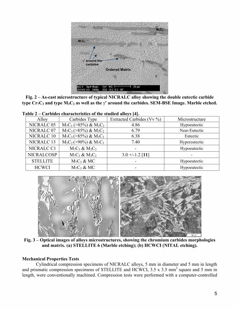
Typical NICRALC as-cast structures are presented in figure 1. The NICRALC alloys have a matrix essentially composed of ordered γ’ with a complex dispersion of carbides. NICRALC C1 (fig. 1-e) and 05 (fig. 1-a) are clearly hypoeutectic, while alloys 07 (fig. 1-b) and 10 (fig. 1-c) demonstrate eutectic carbide distribution. These alloys also display rosette shaped γ/γ’ agglomerates [4]; and NICRALC 13 is hypereutectic (fig. 1-d). Spray-formed NICRALC OSP has an ordered matrix showing dispersed fine primary carbides, and islands of γ’+ γ (black areas in figure 1-f).
Moreover, in the as-cast condition NICRALC alloys display the coexistence of two different carbides, frequently found as “duplex” double carbides (probably the result of the incomplete γ + M7C3
γ’ + M3C2 reaction), as can be seen in figure 2. EDS microanalysis near the carbides indicate the existence of a Cr-depleted, Al-enriched halo around the carbides, with a Ni/Al ratio approaching the

4
binary stequiometric ordered γ’ composition. X-ray analysis of carbides extracted from NICRALC 05, 07, 10 e 13 [4] show the coexistence of M7C3 and M3C2 carbides; Rietveld analysis [4] was used to determine the predominant carbide in each NICRALC alloy as summarized in Table 2.
(a) (b)
(c) (d)
(e) (f)
Fig. 1 – Optical images of alloys microstructures, showing the chromium carbides morphologies and matrix. (a) NICRALC 05; (b) NICRALC 07; (c) NICRALC 10; (d) NICRALC 13; (e) NICRALC C1;
(f) NICRALC OSP (dark areas are formed by γ’+γ).
Carbides present in the STELLITE and HCWCI were mostly M7C3, with small amounts of MC [4]; this carbide corresponds to WC in the STELLITE and NbC in the case of the HCWCI. Typical microstructure is shown in figure 3.
5
Fig. 2 – As-cast microstructure of typical NICRALC alloy showing the double eutectic carbide
type Cr7C3 and type M3C2 as well as the γ’ around the carbides. SEM-BSE Image. Marble etched. Table 2 – Carbides characteristics of the studied alloys [4].
Alloy Carbides Type Extracted Carbides (Vv %) Microstructure NICRALC 05 M7C3 (>85%) & M3C2 4.86 Hypoeutectic NICRALC 07 M7C3 (>85%) & M3C2 6.79 Near-Eutectic NICRALC 10 M7C3 (>85%) & M3C2 6.38 Eutectic NICRALC 13 M3C2 (>90%) & M7C3 7.40 Hypereutectic NICRALC C1 M7C3 & M3C2 - Hypoeutectic NICRALCOSP M7C3 & M3C2 3.0 +/-1.2 [11] -
STELLITE M7C3 & MC - Hypoeutectic HCWCI M7C3 & MC - Hypoeutectic
Fig. 3 – Optical images of alloys microstructures, showing the chromium carbides morphologies
and matrix. (a) STELLITE 6 (Marble etching); (b) HCWCI (NITAL etching).
Mechanical Properties Tests Cylindrical compression specimens of NICRALC alloys, 5 mm in diameter and 5 mm in length and prismatic compression specimens of STELLITE and HCWCI, 3.5 x 3.5 mm2 square and 5 mm in length, were conventionally machined. Compression tests were performed with a computer-controlled
M3C2
Ordered Matrix
γ’ around the carbides
M7C3

6
universal testing machine at a strain rate of 6.7x10⁻³ s-1. Tests were run at room temperature in air. The offset compressive yield stress was measured at 0.2% plastic strain. Fracture toughness was measured using the chevron notch method, following prior results [22, 23, 24]. This method greatly simplifies the determination of the fracture toughness of high strength materials, following mathematical and experimental works performed in the late 1970’s and early 1980’s [25], which made possible the determination of the fracture toughness values from the maximum load measured during testing [26]. The Young modulus and matrix hardness was determined by instrumented micro-hardness, using the Oliver-Pharr [27] model. During the tests was used normal load of 0.98 N. Wear Tests Hard particle erosion tests were performed on a stationary fluidized bed developed by Kunioshi [28], driven by room temperature atmospheric air compressed at 2.4 bar for 300 minutes. The hard particles used were electro-melted, faceted Al2O3, with sizes between 150 and 212 µm. Impact angles may be approximated at 90°, and the maximum velocity was 7.5 m/s. Specimen dimensions were 2.0 x 30.0 x 9.0 mm3 and their surfaces were standardized by grinding at 600 meshes, such that the initial surface average roughness (Ra) was close to 0.10 µm. Sand-rubber-wheel abrasion tests were performed in equipment developed by Ramos [29], with the normal load kept at 130 N using a servomotor. The tangential forces, the number of rotations and the temperature were all monitored throughout the test. The wear tests were run for 600 s using a wheel speed of 200 rpm and abrasive quartz foundry-sand according to specifications AFS 100. For each set of conditions, three runs were performed, each for a length of 2,800 m. All samples were finished by grinding with a 120# abrasive wheel. Samples with 10.5 x 21.0 x 42.0 mm3 were fixed to a steel specimen holder so as to conform to the specifications of [29].
The lubricated wear tests were performed using FALEX equipment (block-on-ring configuration). Parameters used for this wear include the following: a) lubricating oil AGECOM 60 PS with viscosity of 4.8 x 10⁻³ Pa.s at 100ºC; b) testing temperature maintained at 100°C; testing speed 400 rpm; d) normal load 600 N; e) 20000 cycles, corresponding to a sliding distance of 2200 m.
Reciprocating sliding tests were performed on a Plint machine, using the following parameters: a) steel sphere counter bodies made of quenched and tempered SAE 52100, 4.95 mm in diameter, and WC-Co sphere counter bodies, 4.76 mm in diameter; b) sliding frequency of 6.0 Hz; sliding amplitude of 6.0 mm with normal load (dead weight) of 9.806 N; c) 60 minutes test time, amounting to a total sliding distance of 260 m; d) room temperature and without any lubricant; e) room relative humidity was kept below 50%; f) prior to testing, samples were ground with 220 grinding paper for 5 min, leaving surface roughness (Ra) around 0.10 µm. This specific test was run only with STELLITE, NICRALC C1 and NICRALC OSP, all in their as-cast condition [30].
Debris formed both during reciprocating sliding and lubricated block-on-ring tests were collected (by filtering the lubricant in the case of block-on-ring) and analyzed in the SEM-EDS, after being cleaned and coated with Au. Results Table 3 summarizes the mechanical properties results at room temperature. Fracture toughness for all materials increases with decreasing microhardness in a manner similar to correlations found for tool steels [22, 31]. STELLITE, compared to NICRALC 05, 07 and 10, showed a higher microhardness corresponding to a lower toughness; the results for HCWCI show an even stronger correlation [31]. The only exception was the spray-formed NICRALC OSP, probably due to heterogeneities introduced

7
by the fabrication route and the refined microstructure and carbide distribution, and NICRALC 13, which the predominance of brittle M3C2 carbides, instead of the tougher M7C3, promoted a higher damage concentration during fracture.
Room temperature yield strength for NICRALC alloys tested in compression increased monotonically with carbon content and carbide volume fraction, except alloy NICRALC 10; carbide morphology and distribution did not play an important role in this case, but recent work with directionally solidified samples showed significant improvement over conventionally cast alloys when samples were tested with loads parallel to the direction of solidification [4]. Table 3– Summary of room temperature mechanical properties from compression, instrumented microhardness and chevron notch fracture toughness tests
Liga Matrix Hardness - HV0.01 [GPa] E [GPa] σYS [MPa] KICV [MPa . m1/2] Nicralc C1 5.5 +/- 0.18 235. 24 +/- 1.48 610.0 55.2 +/- 3.1
Nicralc OSP 4.13 +/- 0.01 225.39 +/- 4.49 948.3 35.5 +/- 3.6 STELLITE 6 7.07 +/- 0.37 234.47 +/- 12.13 927.0 39.1 +/- 0.8
HCWCI 6.13 +/- 0.09 211.72 +/- 3.70 2.185.0 21.4+/- 0.3 Nicralc 05 3.69 +/- 0.11 222.13 +/- 3.40 507.8 65.8+/- 3.4 * Nicralc 07 - - 576.1 52.6+/- 4.5 Nicralc 10 3.45 +/- 0.08 216.94 +/- 3.40 520.6 59.8** Nicralc 13 4.99 +/- 0.35 235.82 +/- 9.12 1021.9 49.6+/- 4.9
* Values of fracture toughness for alloy 05 are conditional only, because the results did not satisfy all requisites of Linear Elastic Fracture Mechanics as defined by ASTM E-1304 97. ** Individual valid result.
The results of wear resistance tests are summarized in table 4. Generally, there is no direct relationship between the volume loss during wear tests and the hardness and other mechanical properties of the NICRALC alloys. Wear resistance appear to be more directly related to phase morphologies and distributions, mainly the eutectic (for alloys NICRALC C1, 05, 07 e 10) and primary hypereutectic carbides (for alloy NICRALC 13). The best results regarding wear resistance were obtained from alloys NICRALC 07 and 10, both with typical eutectic carbide morphology homogeneously distributed. Table 4 – Summary of the wear tests results obtained in the erosion, abrasion, FALEX and reciprocating sliding tests.
Reciprocating Sliding Volume Loss [10-
4.mm3/m] Alloys Hardness [HV0.5]
Erosion Volume Loss
[mm3/m2]
Abrasion Volume Loss [10-3mm3/m] WC-Co SAE 52100
Lubricated Sliding Volume Loss [10-
6.mm3/m]
NICRALC C1 426.1 0.84 19.2 10.0 37.0 50.5 NICRALC OSP 449.4 3.85 43.6 12.0 24.0 351.5
STELLITE 500.9 0.96 9.2 9.0 1.0 4.2 HCWCI 741.3 4.46 1.9 - 23.8
NICRALC 05 407.9 3.04 22.3 - 507.7 NICRALC07 462.1 3.84 10.7 - 83.1
NICRALC 10 456.7 0.93 7.4 - 35.8 NICRALC 13 482.2 4.27 15.1 - 382.3
Table 5 presents the friction coefficient obtained for each of the different wear tests. For the block-on-ring (Falex) test, the friction coefficients obtained were in the range predicted by the IRG

8
diagram [32] for boundary lubrication regime, which is consistent with the test conditions. The higher friction coefficients were associated with bigger mass losses due to the sliding for the NICRALC alloys. For the reciprocating sliding test the friction coefficient varied significantly based on type of counter-body used: average values measured for SAE 52100 steel showed to be larger than those measured for WC-Co. In the sliding tests, the relationship between mass loss and friction shows that the wear depends on the matrix behaviour and the carbide distribution, so wear is determined by the adherence mechanisms. On the other hand, in the abrasion tests, there was little or no correlation between friction coefficient and mass loss for the wear tests. In this case, the severity of the wear turns negligible the friction mass loss relation. Tabela 5 – Friction values measured for abrasion, lubricated sliding (FALEX) and reciprocating sliding wear tests.
Friction Reciprocating Sliding Alloys Abrasion WC-Co SAE 52100
Lubricated Sliding
NICRALC C1 0.35 +/- 0.01 0.46 +/- 0.04 0.56 +/- 0.06 0.11 +/- 0.010 NICRALC OSP 0.43 +/- 0.01 0.45 +/- 0.04 0.53 +/- 0.05 0.13 +/- 0.005
STELLITE 0.35 +/- 0.01 0.36 +/- 0.05 0.56 +/- 0.09 0.09 +/- 0.005 FOFO CONV 0.40 +/- 0.01 - - 0.12 +/- 0.005 NICRALC 05 0.38 +/- 0.01 - - 0.15 +/- 0.010 NICRALC 07 0.39 +/- 0.01 - - - NICRALC 10 0.39 +/- 0.01 - - 0.10 +/- 0.010 NICRALC 13 0.35 +/- 0.01 - - 0.16 +/- 0.005
Discussion Mechanical Properties The yield strength behaviour of the NICRALC alloys is determined by the carbon amount and the volume fraction of carbides. In this case the mechanical properties increased with the carbon content. The NICRALC OSP is an exception as it shows higher yield strength, despite its lower carbon content. In this case, it is reasonable to attribute this behaviour to a more refined carbide microstructure and grain refinement. In general, the fracture toughness of each of the alloys studied was inversely proportional to hardness and yield strengths. Fracture toughness was controlled by the distribution of second (hard) phases; for NICRALC C1 and STELLITE, the continuous interdendritic distribution of carbides provided a preferential path for crack growth (figures 4-a and 4-b). In those cases, the fracture toughness was defined by both deviations in the crack growth path and by the intrinsic toughness of the carbide phases [31]. In alloys where the carbides are more heterogeneously distributed throughout the matrix, such as NICRALC 05 and 13, the matrix characteristics dominate. The finer and more homogeneously distributed γ’ ordered domains in the matrix improved the higher fracture toughness of alloy NICRALC 05 (figure 4-c), while the larger carbides M3C2 (with their accompanying stress concentration) and coarser ordered domains in NICRALC 13 (figure 4-d) reduced its toughness. Furthermore, there is published evidence [30], that the M3C2, carbides are more brittle than M7C3. The micrograph pictured in figure 4-d clearly shows that the carbides in NICRALC 13 suffer cleavage not only along the main fracture line but along the plastic zone as well, resulting in the creation of secondary cracks.

9
(a) (b)
(c) (d)
Fig. 4 – Crack path in the NICRALC C1 (a), STELLITE (b), NICRALC 05 (c) and NICRALC 13 (d) after chevron fracture toughness tests. SEM-BSE Images. Marble etching.
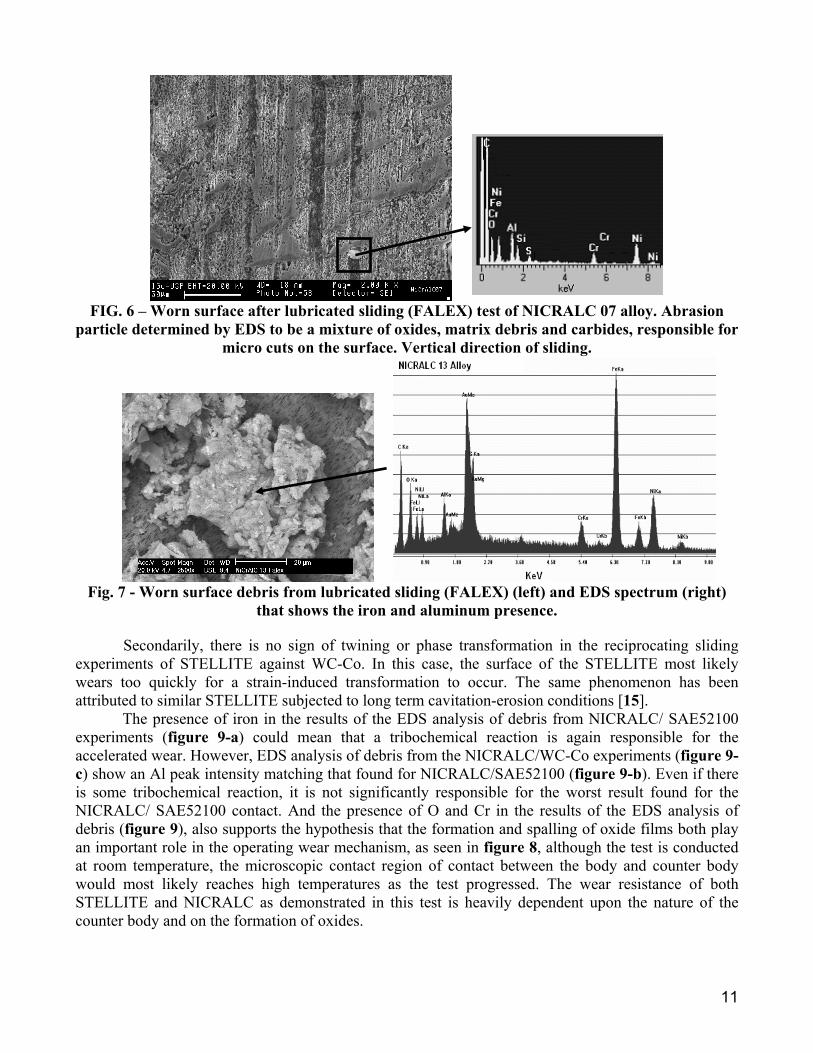
Wear Tests The results from the lubricated sliding block-on-ring test (FALEX) showed that phase distribution, not hardness, was the main determinant of rate of wear. NICRALC alloys generally suffered concentrated damage in the matrix (figure 5-a and 5-c), while the reference alloy STELLITE suffered damage at the carbide-matrix interface (figure 5-b). Figure 5-a also shows cracks formed on M3C2-type carbides. In the case of alloy NICRALC 07 (figure 5-c) wear concentrated heavily on carbide-free regions, mainly in the disordered γ films surrounding γ’ ordered domains. Similar results were found in cavitation-erosion tests [4]. The areas around the carbides (γ’ halos) shows no wear damage. This behaviour can be explained as protection by the carbides associated to the absence of ordered/disordered phase boundaries. No evidence of micro-cracks formation at the matrix was observed. The dominant wear mechanism was determined to be plastic collapse due to adhesion followed by failure of the adhered patch. Co-based STELLITE was supposed to offer wear resistance superior to that offered by NICRALC in both block-on-ring FALEX and reciprocating slide tests due to a tribochemical reaction between the Ni3Al phase and the steel counter bodies. However, subsequent SEM-EDS analysis of the debris collected from both tests caused this hypothesis to be discarded. Figure 6 shows grooves and gouges caused by hard particles abrading the worn surface. EDS analysis of these particles suggested a complex structure formed by a mixture of carbides, oxides and matrix matter. There was no evidence of damage on the layers below the surface. Alloys with eutectic or near-eutectic microstructures with more homogeneous carbide distribution demonstrated improved performance in the block-on-ring lubricated sliding test, a result analogous to the findings of the sand-rubber-wheel abrasion test.
Ordered Matrix
M7C3
WC M7C3
Co-rich matrix
Secondary crack growth by interdendritic carbides
Pro-eutectic Matrix
Cracked M3C2 Carbide
Crack growth by disordered boundary

10
(a) (b)
(c)
Fig. 5 - Wear micromechanisms on the worn surface in lubricated sliding tests (FALEX). (a) NICRALC C1; (b) STELLITE; (c) NICRALC 07. Sliding direction is from the bottom to the
top. Figure 7 shows the strong presence of Fe in the EDS analysis of debris filtered out of the lubricating oil. There is also a small Al peak, possibly an indication of the formation of Fe aluminates through a tribochemical reaction similar to mechanical synthesis. However, this hypothesis is contradicted by the fact that smaller volume losses of the block specimen are associated with higher absolute mass loss of the steel bearing ring counter body. The only exception to this trend is alloy NICRALC 13, in which a large loss of volume of the block correlated to even greater mass loss in the ring. This anomaly was most likely due to the strongly abrasive effect of the large hypereutectic M3C2 type carbides in this particular alloy.
Results obtained in the reciprocating sliding wear tests show a strong dependence on the type of counter body used. In table 4 it can be seen that NICRALC alloys experience significant wear during the use of SAE 52100 spheres, while STELLITE suffered no wear at all. When WC-Co spheres were used, there was almost no difference between the level of wear suffered by the two materials. Two distinct phenomena can explain this paradox: first, the worn surface of STELLITE tested against SAE 52100 (figure 8-c) shows some indications of strain-induced transformation (γCo εCo) or twinning, as described in the literature [15]. The increase in hardness caused by this transformation could help to inhibit wear in the STELLITE by concentrating the damage on the steel spheres. The fact that an increased amount of iron was found on the collected debris from the STELLITE-SAE 52100 experiments (figure 9-c), as compared to that found on the debris that originated from the NICRALC-SAE 52100 (figure 9-b). Experiments seem to confirm this hypothesis.
γ’+ γ
γ’
γ’
γ’
M7C3
M7C3
Worn matrix
M3C2 Cracks
Damage concentrated at Matrix Carbides Interface
Worn matrix
11
FIG. 6 – Worn surface after lubricated sliding (FALEX) test of NICRALC 07 alloy. Abrasion
particle determined by EDS to be a mixture of oxides, matrix debris and carbides, responsible for micro cuts on the surface. Vertical direction of sliding.
Fig. 7 - Worn surface debris from lubricated sliding (FALEX) (left) and EDS spectrum (right)
that shows the iron and aluminum presence.
Secondarily, there is no sign of twining or phase transformation in the reciprocating sliding experiments of STELLITE against WC-Co. In this case, the surface of the STELLITE most likely wears too quickly for a strain-induced transformation to occur. The same phenomenon has been attributed to similar STELLITE subjected to long term cavitation-erosion conditions [15]. The presence of iron in the results of the EDS analysis of debris from NICRALC/ SAE52100 experiments (figure 9-a) could mean that a tribochemical reaction is again responsible for the accelerated wear. However, EDS analysis of debris from the NICRALC/WC-Co experiments (figure 9-c) show an Al peak intensity matching that found for NICRALC/SAE52100 (figure 9-b). Even if there is some tribochemical reaction, it is not significantly responsible for the worst result found for the NICRALC/ SAE52100 contact. And the presence of O and Cr in the results of the EDS analysis of debris (figure 9), also supports the hypothesis that the formation and spalling of oxide films both play an important role in the operating wear mechanism, as seen in figure 8, although the test is conducted at room temperature, the microscopic contact region of contact between the body and counter body would most likely reaches high temperatures as the test progressed. The wear resistance of both STELLITE and NICRALC as demonstrated in this test is heavily dependent upon the nature of the counter body and on the formation of oxides.

12
(a) (b)
(c)
Fig. 8 – Reciprocating Sliding worn surface. (a) NICRALC C1/WC-Co; (b) STELLITE/WC-Co; (c) STELLITE/SAE52100, where can be seen evidences for strain induced twinning or phase
transformation, a strengthening mechanism that can explain the results. STELLITE, which may be strain-hardened through a phase transformation or a twinning mechanism, and HCWCI, which demonstrated higher initial hardness, both showed less weight loss during the abrasive wear test. NICRALC alloys showed a similar trend to that described in previous tests; with wear rates depending more on the distribution and type of carbides than on the strength and hardness of the alloy. NICRALC 05 alloy, hypoeutectic, with smaller hardness and a lower volume fraction of carbides, and NICRALC 13, hypereutectic alloy with higher hardness and a higher volume fraction of M3C2 carbides (table 3) both suffered elevated mass losses. The alloys NICRALC 07, 10 and C1, with intermediate hardness, carbon content and carbide volume fraction, with near-eutectic microstructures, showed less mass loss during wear test. In terms of the sand-rubber-whell tests, micrographs of the worn STELLITE sample (figure 10-a) shows more homogeneous abrasion than that was seen for the NICRALC alloys (figure 10-b). The worn surface of NICRALC alloys shows carbides in high relief, characterizing the lower wear resistance of the NICRALC matrix with respect to the STELLITE matrix. As can be seen from the worn surface of NICRALC 07 alloy (figure 10-b), the homogeneous distribution of carbides gives this alloy and the NICRALC 10 increased wear resistance similar to that shown for STELLITE, and significantly improved over the other NICRALC alloys. In the micrograph for alloy 13 (figure 10-d), it is possible to see fracture and decohesion at the interface of the more fragile M3C2 carbides, signal of evidence of the wear acceleration. The sand-rubber-wheel abrasion tests results obtained in this work are very different from those obtained by pin-on-disk abrasive wear results for both cast and spray-formed NICRALC alloys, published early [11]. In those experiments NICRALC showed wear resistance greater than or similar to
Worn Damage
Slip Planes
Fresh MatrixCr Carbides
Al and Cr OxidesCr Oxides
Broken Carbide

13
HCWCI, when tested as pins against SiC sandpaper disks, a fact which provides evidences of the strong influence of the tribological system is evidenced. Sand-rubber-wheel abrasion tests, in which silica particles (softer than some of the carbides) are free to roll, present conditions much different from those of the pin-on-disk wear test, in which much harder SiC particles are glued to the disk paper. Additionally, the geometry of the pin-on-disk test is such that the pin must pass many times over the same spot on the disk [33].
(a) (b)
(c) (d)
Fig. 9 – SEM/EDS of wear residues from alternating sliding experiments without lubrication. (a) NICRALC C1/AISI 52100 steel; (b) NICRALC C1/WC-Co; (c) STELLITE/AISI 52100 steel; (d)
STELLITE / WC-Co. The Fe peaks are indicated by the arrows. Results for the erosion tests were consistent with the other tests in that the wear resistance of the NICRALC alloys was heavily dependent on the carbide distribution and carbide type present. Alloys NICRALC 10 (eutectic) and C1 showed the best results and similar to STELLITE behaviour, confirming the poor wear resistance of the γ+γ’ matrix. Finer carbide distribution provided better protection for the matrix, thus minimizing wear. Figure 11 shows the eroded surfaces of some materials tested in this work, further demonstrating that the main erosion mechanism is plastic deformation of the matrix. Due to the relatively small energy of the individual impacts of abrasive particles on the surface studied in this work, the craters described in the literature [13] are not evident. It is possible to see mechanisms of plateau formation (plate-like), lips and cracks in all materials. Cracks evidences are indicated by arrows. These cracks link wear with crack propagation, a fact which could help explain the high wear rate of the HCWCI, a low fracture toughness material.

14
(a) (b)
(c) (d)
FIGURE 10– Details of the worn surfaces after sand rubber wheel abrasion tests (a) STELLITE; (b) NICRALC 07; (c) NICRALC 13; (d) details of the damage suffered by M3C2 carbides in alloy
NICRALC 13. SEM-backscattered electrons. With regard to NICRALC the link between fracture toughness and loss of mass during erosion tests is not as obvious as is in the case of HCWI. Alloys NICRALC C1 and NICRALC 10, with intermediate fracture toughness were less eroded. Alloys as distinct as NICRALC 05 and 13 (respectively the larger and the smaller fracture toughness) presented mass losses of the same magnitude, as did NICRALC 07 and NICRALC OSP, two alloys with distinct microstructures and mechanical properties. It appears that the larger mass loss are associated with the smaller fracture toughness, except for alloy NICRALC 5, but the determining factor is the carbide distribution , not the fracture toughness. For the other wear tests it seems reasonable to assume that there is no correlation between fracture toughness and wear rate, as wear occurs mainly by a cutting and deformation of the ordered phase mechanisms, independent of the carbon content. There was some evidences of carbide cracking during wear (figure 4-a), but no direct evidence that those cracks contribute to the overall wear rate.
Worn Matrix
Broken M3C2
Carbide
Stellite Worn Surface
Larger M7C3 carbide
Eutectic Carbides
Eutectic Carbides
M3C2 Carbides
Worn Matrix

15
(a) (b)
(c)
Fig. 11 – Erosion wear surfaces. (a) NICRALC C1 alloy; (b) STELLITE; (c) HCWCI.
Hypereutectic NICRALC 13 alloy, despite having greater volume fraction of carbides and higher hardness, presented a higher mass loss than all other NICRALC alloys except NICRALC 5 in wear as well as erosion and sliding tests. This result is related not only to the smaller fracture toughness of the alloy and the intrinsic brittleness of the M3C2 type carbides, but mainly to the coarse distribution of carbides, which leaves unprotected matrix areas unlike the eutectic alloys. . Conclusions
As-cast NICRALC alloys with different C contents and different primary carbide distributions (hypo, eutectic and hypereutectic), were compared with a spray-formed NICRALC alloy, an as-cast STELLITE 6 and a conventionally as-cast high chromium white cast iron.
The yield strength of NICRALC alloys was directly dependent of carbon content and volume fraction of carbides. The spray-formed alloy is an exception, due mainly to its more refined microstructure. The fracture toughness of NICRALC was inversely proportional to both hardness and yield strength. The carbide distribution plays an important role, like in the case of the NICRALC OSP. The carbide type has a role too, as shown in the case of NICRALC 13 alloy which contains predominantly M3C2 carbides, weaker than M7C3.
In general manner, STELLITE alloy showed higher wear resistance than NICRALC alloys at room temperature. This result can be explained by the higher matrix hardness of STELLITE at room temperature and the phase transformation induced strengthening of its matrix.
In the reciprocating sliding tests of NICRALC and STELLITE the wear resistance varied with the counter body material; tests performed using WC-Co spheres as counter bodies resulted in similar
Crack
CrackCrack

16
results for both NICRALC and STELLITE alloys, while when using AISI 52100 steel spheres the STELLITE was much more wear resistant.
In NICRALC alloys wear damage is primarily controlled by the matrix resistance, while in STELLITE wear is controlled by damage to the carbides.
Under abrasion, erosion and lubricated sliding wear tests, the best results of NICRALC alloys were obtained for the alloys which presented more homogeneous carbide distributions (eutectic alloys). For those eutectic alloys the results obtained were similar to the results obtained for STELLITE.
There is no evidence of a strict relation between fracture toughness and wear resistance of NICRALC alloys. On the other hand, the lower fracture toughness can be associated with the higher erosion mass loss of the HCWCI. For NICRALC the larger erosion mass loss was associated with the worst fracture toughness (NICRALC OSP and NICRALC 13). Acknowledgments The authors would like to tanks the financial support of FAPESP, CNPq and CAPES. IPT for HCWCI donation and Professors Cláudio Kiminami, Claudemiro Bolfarini e Dr. Aroldo Mourisco (in memoriam) for NICRALC OSP preparation. This work is dedicated to Dr. Mourisco . Bibliography [1] YOSHIMURA, H.N.; MATSUBARA, Y.; GOLDENSTEIN, H., “WCI – White Cast Intermetallic Compound – A New
High Temperature Foundry Material”. Acta Microscopica. Vol.6, Supl. A, p. 174-175, September, 1997. [2] GOLDENSTEIN, H., SILVA, Y.N., YOSHIMURA, H.N., “Designing a New Family of High Temperature Wear
Resistant Alloys Based on Ni3Al IC - Experimental Results and Thermodynamic Modelling”, Intermetallics, 2001. [3] SILVA, Y.N., “CARACTERIZAÇÃO MICROESTRUTURAL E VALIDAÇÃO DE BANCO DE DADOS
TERMODINÂMICO PARA SIMULAÇÃO DE PROPRIEDADES DE LIGAS DO SISTEMA AL-C-CR-NI”,
Dissertação de Mestrado em Engenharia Metalúrgica e de Materiais, PMT/EPUSP, Julho de 2003, São Paulo/SP – Brasil. [4] Silva, W.S., Avaliação das Propriedades Mecânicas e Tribológicas de Ligas NICRALC, Tese de Doutorado, EPUSP
2006. [5] YANG, J.M., CAO, W.H., LIU, C.T., “DEVELOPMENT OF NICKEL ALUMINIDE MATRIX COMPOSITES”,
Materials Science Engineering, Vol A 107, 1989, pp. 81. [6] BULLOCK, E.; McLEAN, M.; MILES, D.E., “Creep behaviour of a Ni-Ni3Al-Cr3C2 eutectic composite”,. Acta Met.,
v.25, p.333-344, 1977. [7] NEMOTO, M.; TIAN, W.H.; HAN, C.S.; SANO, T., “Dislocation-particle interactions in precipitation strengthened
Ni3Al and NiAl”. In: Structural Intermetallics, eds. R.Darolia et al, TMS, 1993. Proceedings. p.551-560. [8] FARINA, A. B.; GOLDENSTEIN, H.; SILVA, W. S.; BENEDUCE NETO, F., “Progressos no desenvolvimento do
banco de dados termodinâmicos para o sistema Ni-Cr-Al-C”. In: XVI CBECIMAT, 2004, Porto Alegre - RS. v. XVI, p. 1-13.
[9] HISATO, M. K.,” Estudos de Fundibilidade de uma Liga NiCrAlC”. Trabalho de Formatura, PMT/EPUSP, 2005. [10] Silva, W.S., Ferrandini, P.L., Caram, R., Goldenstein, H., Estudo da Resistência Mecânica de Ligas NICRALC em
diferentes temperaturas, XVII CBECIMAT, Foz do Iguaçu, 2006 [11] MOURISCO, A.; SILVA, Y.N.; GOLDENSTEIN, H.; KIMINAMI, C.S.; BOLFARINI, C., “Microstructure of Wear
Resistant Nickel Alloys Produced by Spray Forming”, In: EUROMAT’2001, 2001, Rimini. Proceedings of the EUROMAT 2001. Associazone Italiana di Metallurgia / FEMS, 2001.
[12] MAZUR, R.L., “ SOLID PARTICLE EROSION IN NI-BASED SUPERALLOYS, MASTER THESIS, UNESP-GUARATINGUETÁ, 2004.
[13] S.B. MISHRA A, K. CHANDRA A, S. PRAKASH A., B. VENKATARAMAN, “Characterisation and erosion behaviour of a plasma sprayed Ni3Al coating on a Fe-based superalloy”, Materials Letters 59 (2005) 3694 – 3698
[14] S.J. Matthews, B.J. James , M.M. Hyland, Microstructural influence on erosion behaviour of thermal spray coatings, Materials Characterization 58 (2007) 59–64.
[15] D´OLIVEIRA, A. S. C. M. ; XIAOJUN, Z. ; PROCOPIAK, L. A. ; SOUZA, N. C. . PHASE TRANSFORMATION DURING CAVITATION EROSION OF A Co STAINLESS STEEL. Materials Science & Engineering. A, Structural Materials: properties, microstructure and processing, v. 358, n. 1-2, p. 199-204, 2003
17
[16] ADRIANO EIDI YAEDU, INFLUÊNCIA DO SUBSTRATO NA DEPOSIÇÃO DE STELLITE 1 COM PLASMA DE ARCO TRANSFERIDO, Dissertação de Mestrado – UFPR, 2003.
[17] So, H.; Chen, C. T.; Chen, Y. A. Wear behaviours of laser-clad stellite alloy 6. Wear, vol. 192, p. 78 – 84, 1996. [18] MARU, M.M., Estudo do Desgaste e Atrito de um par metálico sob deslizamento lubrificado, Tese de Doutorado,
EPUSP, 2003. [19] I. Sevim, I. Eryurek, Effect of fracture toughness on abrasive wear resistance of steels, Materials and Design 27 (2006)
911–919 [20] Xu Liujie, Xing Jiandong, Wei Shizhong, Zhang Yongzhen, Long Rui, Investigation on wear behaviors of high-
vanadium high-speed steel compared with high-chromium cast iron under rolling contact condition, Materials Science and Engineering A 434 (2006) 63–70
[21] Hans Berns, H., Comparison of wear resistant MMC and white cast iron, Wear 254 (2003) 47–54 [22] Silva, W.S., Estudo da tenacidade à fratura do aço rápido M2 fundido, modificado e tratado termicamente, Dissertação
de Mestrado, EPUSP, 2001. [23] MENDANHA, A., Tenacidade à fratura de aço para trabalho a frio, Dissertação de Mestrado, EPUSP, 2004. [24] W.S. da Silva, J.T.N. Medeiros, H. Goldenstein, fracture toughness of as-cast, conventional and sintered from powder high-speed tool steels, 7TH TOOLING CONFERENCE, Torino, 2006. [25] Newman, J. C. "A Review of Chevron-Notched Fracture Specimens", in Chevron Notched Specimens – Testing and
Stress Analysis. Editors: Underwood, Freiman & Barata, ASTM Committee E-24 on Fracture Testing, Louisville, Ky, 21 April 1983.
[26] ASTM E1304 – 97, “Standard Test Method for Plane-Strain (Chevron-Notch) Fracture Toughness of Metallic Materials”, ASTM Committee E-24, Annual Book of ASTM Standards, 1989, p 962-972
[27] OLIVER W.C., PHARR, G.M., “A new improved technique for determining hardness and elastic modulus using load and sensing indentation experiments”, Journal of Materials Research, v7.n6, pp.1564-1582, 1992.
[28] Kunioshi, C. T. ESTUDO DO COMPORTAMENTO DE EROSÃOOXIDAÇÃO DE MATERIAIS COMPÓSITOS DE NiCr COM WC E Cr3C2. Tese de Doutorado, IPEN-CNEN, 2003.
[29] RAMOS, L.V., “CONSTRUÇÃO E INSTRUMENTAÇÃO DE ABRASÔMETRO DO TIPO RODA-DE-BORRACHA PARA O ESTUDO DO COMPORTAMENTO TRIBOLÓGICO DE AÇOS”. Dissertação de Mestrado, EPUSP, 2005.
[30] Mello, J.D.B, Tribological Behavior of multi-component ferrous alloys, International Conference Abrasion 2005, São Paulo, Brazil, p. 19-45.
[31] BROECKMANN, C., “Fracture of Tool Steels on a Microscopical Scale”. Proc. Conf. Tooling – Progress in Tool Steels, 1996, p.491-499.
[32] [31]GEE, A.W.J., BEGELINGER, A., SALOMON, G., “Failure mechanisms in sliding lubricated contacts”, in: Mixed lubrication and lubricated wear, Proceedings of the 11 Leeds-Lyon Symposium, England, p.108.
[33] SINATORA, A., ALBERTIN, E., Personal communication, Apud, (2002)