starter kit guide - mouser.com guide-838459.pdf · the sk-fm4-176l-s6e2cc starter kit includes an...
TRANSCRIPT

Starter Kit Guide
32-bit ARM® Cortex®-M4F based Microcontroller S6E2CC Series
Publication Number FM4_AN709-00010 Revision 1.1 Issue Date March 26, 2015

U s e r M a n u a l
Target products This starter kit document supports evaluating features on these products:
Series Product Number (not including package suffix) S6E2CC Series S6E2CC8, S6E2CC9, S6E2CCA
S6E2C1 Series S6E2C18, S6E2C19, S6E2C1A
S6E2C2 Series S6E2C28, S6E2C29, S6E2C2A
S6E2C3 Series S6E2C38, S6E2C39, S6E2C3A
S6E2C4 Series S6E2C48, S6E2C49, S6E2C4A
S6E2C5 Series S6E2C58, S6E2C59, S6E2C5A
2 FM4_AN709-00010-1v1-E, March 26, 2015

U s e r M a n u a l
Table of Contents 1. Introduction ..................................................................................................................................... 5 2. How to Use the SK-FM4-176L-S6E2CC Starter Kit ........................................................................ 7 3. Hardware Description ..................................................................................................................... 7
3.1 MCU and Base Level Components of the Hardware ........................................................... 8 3.1.1 MCU ................................................................................................................... 8 3.1.2 Arduino Interface ................................................................................................ 8 3.1.3 User Button and User LED ................................................................................. 9 3.1.4 Multicon Interface ............................................................................................... 9
3.2 Codec, pSRAM, and Ethernet ............................................................................................. 9 3.2.1 Codec ................................................................................................................. 9 3.2.2 pSRAM ............................................................................................................. 10 3.2.3 Ethernet ............................................................................................................ 10
3.3 Programming and Debug Options ..................................................................................... 10 3.3.1 Cortex Microcontroller Software Interface Standard – Debug Access Port
(CMSIS-DAP) ................................................................................................... 10 3.3.2 JTAG ................................................................................................................ 10 3.3.3 USB Direct ......................................................................................................... 11
3.4 Additional Board Features ................................................................................................. 11 3.4.1 USB ................................................................................................................... 11 3.4.2 Acceleration Sensor .......................................................................................... 11 3.4.3 Light Sensor ...................................................................................................... 11
4. Software Development ................................................................................................................. 12 4.1 Source Code ..................................................................................................................... 12 4.2 Tool Options ...................................................................................................................... 12 4.3 Using the Example Software in the Template with PDL .................................................... 13
4.3.1 Program with CMSIS-DAP JTAG Emulator with IDE, IAR ................................ 13 4.3.2 Program with USB Direct Programmer and ROM Bootloader .......................... 17
5. Additional Information ................................................................................................................... 19
March 26, 2015, FM4_AN709-000010-1v1-E 3

U s e r M a n u a l
4 FM4_AN709-00010-1v1-E, March 26, 2015

U s e r M a n u a l
1. Introduction
The SK-FM4-176L-S6E2CC Starter Kit provides a low-cost solution to quickly start development on an ARM® Cortex®-M4 microcontroller. The board features peripheral devices to demonstrate the features of the FM4 S6E2CCA microcontroller. It also has an Arduino-compatible interface to connect with shields, making application development options limitless. The FM4 S6E2CCA microcontroller comes pre-programmed with an interactive application to test all of the on-board features using a virtual communication port to send message prompts, input test parameters, and output test results.
This document is the guide for the SK-FM4-176L-S6E2CC.starter kit. It provides a hardware description for the kit and software development resources for application development.
This document covers three versions of the starter kit:
• SK-FM4-176L-S6E2CCA
• SK-FM4-176L-S6E2CCA-ETH
• SK-FM4-176L-S6E2CCA-VOI
Kit Features:
Feature SK-FM4-176L-S6E2CC SK-FM4-176L-S6E2CC-ETH SK-FM4-176L-S6E2CC-VOI
Spansion FM4 Family S6E2CCA MCU
CMSIS-DAP JTAG adapter
Ethernet RJ45 (IEEE802.3)
USB device interface
32Mbit quad SPI flash memory
16Mbit external PSRAM memory
Stereo codec
Voice enabled controller
RGB LED
Acceleration sensor
Phototransistor
User button
Arduino-compatible interface
10-pin JTAG interface
Microphone
March 26, 2015, FM4_AN709-000010-1v1-E 5

U s e r M a n u a l
6 FM4_AN709-00010-1v1-E, March 26, 2015

U s e r M a n u a l
2. How to Use the SK-FM4-176L-S6E2CC Starter Kit To initially start with the SK-FM4-176L-S6E2CC starter kit, you should follow the Quick Start Guide. This will guide you through the initial steps of powering the board and running the preprogrammed demonstrations.
To begin actual development, the software resources are found on the product page for the SK-FM4-176L-S6E2CC Starter Kit. Within the software resources are all the components needed for application development on the S6E2CC device and programming tools.
3. Hardware Description The SK-FM4-176L-S6E2CC starter kit includes an S6E2CC device, a CMSIS-DAP JTAG emulator, and external devices to interface to the on-chip peripherals of the S6E2CC device.
This section provides information on how to operate these external devices and how to interface with the S6E2CC device.
March 26, 2015, FM4_AN709-000010-1v1-E 7

U s e r M a n u a l
3.1 MCU and Base Level Components of the Hardware This section contains information on the MCU, Aduino interface, user button and user LED, and the Multicon interface.
3.1.1 MCU The S6E2CC device is part of the 32-bit, general-purpose series based on the ARM Cortex-FM4 processor core with 2 MB flash memory and 256 KB SRAM. The series, which features DSP and floating point (FPU) functions, covers the highest end of the product range. The S6E2CC Series has an I2S port for communication with an audio codec and an external memory bus to interface with system pSRAM. Standard peripheral functions such as timers, ADCs, DACs, and communication and display interfaces are also included.
The S6E2CC device on the SK-FM4-176L-S6E2CC starter kit board is factory programmed with a board test application that checks peripherals. For full details of how to run the board test application, refer to the Quick Start Guide.
3.1.2 Arduino Interface The following table and figure show the interconnects provided for the standard Uno3 Arduino Shields. The table is useful for planning your design and pin usage. The figure after the table is useful for debugging the interface.
Pin No. Pin Name Arduino I/F
ArduinoConnector
designation Multicon 1 VCC34 P38/ADTG_2/DTTI0X_0/S_WP_0 CN7 - pin 146 P40/SIN3_1/RTO10_0/TIOA0_0/AIN0_0/INT23_0/MCSX7_0 DIG10-6/SPI_SI/MFT_PWM CN7 - pin 4 CN12 - pin 747 P41/SOT3_1/RTO11_0/TIOA1_0/BIN0_0/MCSX6_0 DIG10-7/SPI_SO/MFT_PWM CN7 - pin 5 CN12 - pin 248 P42/SCK3_1/RTO12_0/TIOA2_0/ZIN0_0/MCSX5_0 DIG10-8/SPI_CLK/MFT_PWM CN7 - pin 6 CN12 - pin 149 P43/SIN15_0/RTO13_0/TIOA3_0/INT04_0/MCSX4_0 DIG8-4/MFT-PWM CN9 - pin 4 CN12 - pin 650 P44/SOT15_0/RTO14_0/TIOA4_0/MCSX3_0 DIG8-6/MFT-PWM CN9 - pin 6 CN12 - pin 851 P45/SCK15_0/RTO15_0/TIOA5_0/MCSX2_0 DIG8-7/MFT-PWM CN9 - pin 755 P7D/SCK1_1/RX2_0/DTTI1X_0/INT05_0/WKUP2/MCSX1_0 DIG10-1/DTTIX 57 INITX Power - 4 CN-8 pin 363 PF0/SCS63_0/RX2_1/FRCK1_1/TIOA15_1/INT22_1 DIG10-3/SPI_CS/PWM CN7 - pin 3 CN12 - pin 571 PF3/RTO11_1/TIOB6_1/INT05_1/MCASX_0 DIG8-8/IO/BT CN9 - pin 872 PF4/RTO12_1/TIOA7_1/INT06_1/MSDWEX_0 DIG10-2/PWM CN7 - pin 273 PF5/RTO13_1/TIOB7_1/INT07_1/MCSX8_0 DIG8-3/IO/BT CN9 - pin 575 PF7/RTO15_1/TIOB14_1/INT21_1/MSDCLK_0 CN9 - pin 394 P10/AN00/SIN10_0/TIOA0_2/AIN0_2/INT08_0 ANA-6 CN10 - pin 695 P11/AN01/SOT10_0/TIOB0_2/BIN0_2 ANA-5 CN10 - pin 596 P12/AN02/SCK10_0/TIOA1_2/ZIN0_2 ANA-4 CN10 - pin 497 P13/AN03/SIN6_1/RX1_1/INT25_1 ANA-3 CN10 - pin 398 P14/AN04/SOT6_1/TX1_1 ANA-2/SDA1 CN10 - pin 299 P15/AN05/SIN11_0/TIOB1_2/AIN1_2/INT09_0 DIG10-10/SCK2
100 P16/AN06/SOT11_0/TIOA2_2/BIN1_2 DIG10-9/SDA2 CN7 - pin 9101 P17/AN07/SCK11_0/TIOB2_2/ZIN1_2 CN7 - pin 10102 PB0/AN16/SCK6_1/TIOA9_1 ANA-1/SCK1 CN10 - pin 1106 P18/AN08/SIN2_0/TIOA3_2/INT10_0 DIG8-2/UART_RX CN9 - pin 2107 P19/AN09/SOT2_0/TIOB3_2/INT24_1/TRACECLK DIG8-1/UART_TX CN9 - pin 1
8 FM4_AN709-00010-1v1-E, March 26, 2015

U s e r M a n u a l
3.1.3 User Button and User LED There is a user button and a user tri-color LED on the SK-FM4-176L-S6E2CC starter kit board.
Port MCU Pin Number External Device P20/NMIX 85 SW2 – User Button
P1A 108 LED4 – Red
PB2 104 LED4 – Green
P18 106 LED4 – Blue
INITX 57 SW1 – MCU Reset
3.1.4 Multicon Interface The Multicon interface, CN12, is a 2x5 pin connector interface that brings the appropriate signals for UART, SPI, and I2C interfacing off board. A simple 10-pin cable can be used to route the serial signals and power to a secondary board or system. Pins 9 and 10 connect to an extra connector, CN13, to provide another optional off board connection point.
For additional detail, refer to the schematic.
3.2 Codec, pSRAM, and Ethernet The SK-FM4-176L-S6E1CC-VOI board features a voice-enabled S6E2CC device. The SK-FM4-176L-S6E1CC-VOI and SK-FM4-176L-S6E1CC-ETH boards have Ethernet connectivity. All SK-FM4-176L-S6E1CC boards have external 2 MB of pSRAM.
3.2.1 Codec The WM8731 (U3) codec is connected to the I2S and I2C peripheral interfaces of the S6E2CC. The codec is a low-power stereo with an integrated headphone driver. It offers the unique ability to independently program the ADC and DAC sample rates from a single clock source. The respective sample rates from the clock source are on signals ADCLRC and DACLRC.
March 26, 2015, FM4_AN709-000010-1v1-E 9

U s e r M a n u a l
The analog switch SN74LVC1G3157DBVR (U4) controls the clock selection to interface to the ADCLRC or DACLRC for transmission. The default status of the analog switch SN74LVC1G3157DBVR (U4) is the DAC (B2) connected to the I2S module interface of the S6E2CC device. To connect the ADC (B1) to I2S module interface of the S6E2CC device, set the S signal to low.
There is a microphone jack, a headphone jack, and a line-in jack connected to the codec for specific application use options.
• CN11 is a microphone jack • CN5 is a headphone jack • CN6 is a line-in jack
For additional detail, refer to the schematic. The I2C address is 0x1A.
3.2.2 pSRAM The SV6P1615UFC (U5) is a 2 MB pSRAM connected to the external bus interface of the S6E2CC device. The connection to the pSRAM uses 20 address lines, 16 data lines, and 6 control lines.
For additional detail, refer to the schematic.
3.2.3 Ethernet The Ethernet interface of the S6E2CC is connected to an Ethernet circuit consisting of a PHY and RJ45 to enable full Ethernet application development. The KSZ8091 is a single-supply 10Base-T/100Base-TX Ethernet PHY for transmission and reception of data and supports twisted pair (UTP). The J00-0045NL (CN4) is a standard 10/100 Base-TX RJ45 connector with integrated magnetics that is IEEE 802.3 compliant.
For additional detail, refer to the schematic.
3.3 Programming and Debug Options 3.3.1 Cortex Microcontroller Software Interface Standard – Debug Access
Port (CMSIS-DAP) The CMSIS-DAP provides an on-board JTAG emulator to enable programming and debugging of the S6E2CC device. The CMSIS-DAP is supported by all major IDEs. See the list in Section 4.4. The CMSIS-DAP also provides a virtual communication port that connects to the UART0 of the S6E2CC device.
The CMSIS-DAP module provides power to the SK-FM4-176L-S6E2CC starter kit board via the CN2 connector when J4 is in 1-2 position. The CMSIS-DAP firmware solution supports full JTAG configuration and a two-wire connection to the Serial Wire Debug (SWD) interface.
The CMSIS-DAP firmware can be updated with new revisions when necessary. For step-by-step instructions of updating the CMSIS-DAP firmware, see Support Software download cmsisdap_fw_update.zip.
3.3.2 JTAG The SK-FM4-176L-S6E2CC starter kit board has the option to populate the CN1 to connect an external JTAG emulator from a third party vendor. CN1 is a standard ARM 10-pin Cortex debug pinout.
For more information on standard ARM debug pin outs, go to infocenter.arm.com.
10 FM4_AN709-00010-1v1-E, March 26, 2015

U s e r M a n u a l
3.3.3 USB Direct USB Direct is a method to program the S6E2CC device serially by invoking an internal ROM bootloader. There is an application, Flash USB Direct Programmer that is part of the SK-FM4-176L-S6E2CC CD contents download (path ..//SK-FM4-176L-S6E2CCA_CDv1.1/Tools/USBDIRECT-V01L11/setup.exe.) The tool communicates with the ROM bootloader through a graphical user interface. The Flash USB Direct Programmer can program, erase, and verify memory contents of the S6E2CC device
To invoke the internal ROM boot loader, see the table below for jumper settings.
Jumper and Position Pin Number Pin Function J2 closed 85 MD0 – mode pin
J3 2-3 position 172 P60 – port to select USB or UART boot method.
J4 2-3 position N/A Power board via USB CN3
After all jumpers have been positioned properly, connect a USB cable between CN3 and PC. The ROM bootloader will be invoked when MD0 and P60 are high level through a reset or power on. See Program with USB Direct Programmer and ROM Bootloader for step by step instructions.
3.4 Additional Board Features This section describes the USB device, acceleration sensor, and phototransistor features that are on the SK-FM4-176L-S6E2CC starter kit board.
3.4.1 USB Connector CN3 is a micro-B connector that interfaces to the USB0 peripheral of the S6E2CC device to enable development of USB device applications. Note, the SK-FM4-176L-S6E2CC starter kit supports USB device function only, but the USB peripheral on the S6E2CC supports both device and host operation. Transistor MMC8550 is used to force a termination of the USB communications.
3.4.2 Acceleration Sensor The KXCJK is a low power tri-axis accelerometer that interfaces to the I2C peripheral of the S6E2CC device. The KXCJK features user-selectable g-force range and output data rate and configurable resolution. The I2C address is 0x0E.
3.4.3 Light Sensor PT11-21C/L41/TR8 is a phototransistor in a miniature SMD package that can be used for applications as an opto-electronic switch, video, and infrared-applied system. PT11-21C/L41/TR8 (Q3) interfaces to the S6E2CC device via the analog module at pin 103, AN17.
March 26, 2015, FM4_AN709-000010-1v1-E 11

U s e r M a n u a l
4. Software Development This section contains information for the software resources that are available to support the S6E2CC device and SK-FM4-176L-S6E2CC starter kit.
4.1 Source Code The software resources provided with the SK-FM4-176L-S6E2CC starter kit includes:
• Peripheral Driver Library (PDL) with API driver functions
• Prebuilt templates with PDL integrated for IAR, Keil, and Atollic
• Examples to demonstrate use of all S6E2CC device peripherals
• Examples to demonstrate the SK-FM4-176L-S6E2CC starter kit features and target applications
The Peripheral Driver Library (PDL) API set is a full suite of pre-written functions to initialize and operate the on-chip
peripherals. It is part of the SK-FM4-176L-S6E2CC CD contents download. The examples in the PDL folder demonstrate the APIs being used to initialize, set the mode, and configure each peripheral.
There are additional examples that are specific to the SK-FM4-176L-S6E2CC starter kit features in the Spansion Software Lab download. These application examples provide a starting point for initial software development on the SK-FM4-176L-S6E2CC starter kit board.
4.2 Tool Options The S6E2CC series is supported by several 3rd party tool vendors, and you have the option to select your preferred vendor. For demonstrating examples, three main IDEs are supported by having a prebuilt template and examples with the PDL integrated. The main.c and pdl_user.h of any example can be copied and pasted into the source folder, and then opened and compiled for immediate use in any one of these IDEs:
• Keil ARM RealView® Microcontroller Development System
• IAR Embedded Workbench for ARM
• Atollic GCC Compiler
Download evaluation versions of these tools from the vendors’ websites. A full license may necessary to build or debug some of the examples. For detailed information on using the tools, see the documentation in the tool chain help section or on the website of the tool supplier.
12 FM4_AN709-00010-1v1-E, March 26, 2015

U s e r M a n u a l
4.3 Using the Example Software in the Template with PDL This section is to provide step by step guide to programming an example into the S6E2CC device on the SK-FM4-176L-S6E2CC Starter Kit using two of the methods in Section 3.3:
• CMSIS-DAP JTAG emulator with IDE
• USB Direct Programmer with internal ROM boot loader
4.3.1 Program with CMSIS-DAP JTAG Emulator with IDE, IAR Follow the step by step instructions to program a simple GPIO toggle into the S6E2CC using IAR Embedded Workbench for ARM.
1. Download IAR Embedded Workbench for ARM 2. Download SK-FM4-176L-S6E2CCA_CD.zip and extract
− Note: If you did not follow the Quick Start Guide instructions for installing the USB drivers do so now.
3. Connect the board at CN2 via a USB cable to PC 4. Open and extract the S6E2CC_PDL v0.2.zip file at path ..//SK-FM4-176L-S6E2CCA_CD/sw_examples 5. Open the folder at path ..//SK-FM4-176L-S6E2CCA_CDv1.1/sw_examples/S6E2CC_PDL
v0.2/example/gpio/gpio_ports 6. Copy both the main.c and pdl_user.h files 7. Paste the files into folder at path ..//SK-FM4-176L-S6E2CCA_CDv1.1/sw_examples/S6E2CC_PDL
v0.2.zip/S6E2CC_PDL v0.2/template/source. Choose Copy and Replace to write over the existing main.c and pdl_user.h. A backup copy of the main.c and pdl_user.h will be in the backup folder.
− Note: The example will now be available in the workspace of the IDE. To open the IAR workspace, continue following the steps.
8. Open folder at path ..//SK-FM4-176L-S6E2CCA_CDv1.1/sw_examples/S6E2CC_PDL v0.2.zip/S6E2CC_PDL v0.2/template/IAR/s6e2CC_pdl.eww or open IAR workbench and select File/Open/Workspace and browse to s6e2CC_pdl.eww
9. Select Project/Options and ensure that the project settings are as shown in steps 10 through 18. If they are not, change it to be the same as shown by browsing to the correct file within the project template.
− Note: All necessary linker and programming algorithm files exist within template.
March 26, 2015, FM4_AN709-000010-1v1-E 13

U s e r M a n u a l
10. General Options:
11. Linker
14 FM4_AN709-00010-1v1-E, March 26, 2015
U s e r M a n u a l
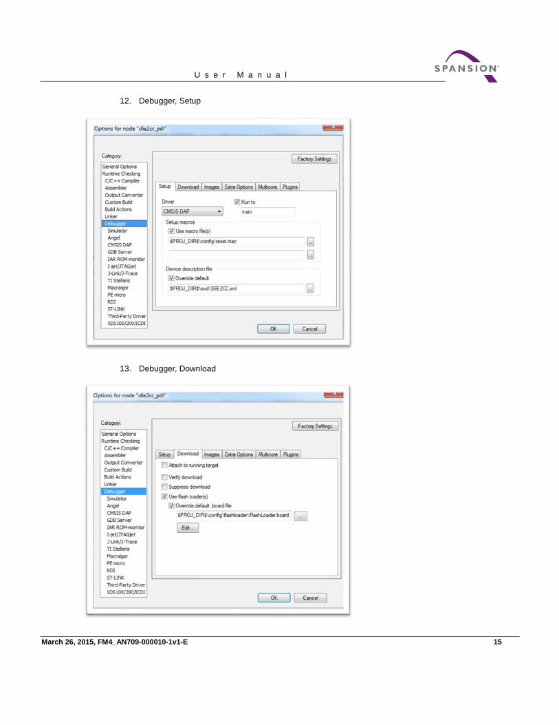
12. Debugger, Setup
13. Debugger, Download
March 26, 2015, FM4_AN709-000010-1v1-E 15

U s e r M a n u a l
14. In main.c change the first two function call to replace P50 with PB2. And the Gpio1pin_Put to set the pin to 0. The modification should look like the below code snipit.
15. In tool bar menu, select Project/Rebuild All
16. Download and Debug select the icon.
− Note: This will direct IAR to connect to the target MCU via JTAG, download the program and enter the debug session. The debugger will halt at main.c if steps 10 through13 are correctly set.
17. In the debug window, select to run the application
18. icon halts the program 19. Program should halt on last statement, as shown.
20. The green LED (LED4) should be illuminated
16 FM4_AN709-00010-1v1-E, March 26, 2015

U s e r M a n u a l
4.3.2 Program with USB Direct Programmer and ROM Bootloader Follow the step-by-step instructions to program the binary of the board test program.
1. Browse to path ..//SK-FM4-176L-S6E2CCA_CDv1.1/Tools in the downloaded CD, and extract USBDIRECT-Vnn.zip
− Note: If you did not follow the Quick Start Guide instructions for installing the USB drivers do so now.
2. Run the setup.exe in the path ..//SK-FM4-176L-S6E2CCA_CDv1.1/Tools/USBDIRECT-Vnn folder. 3. An auto installer will start. Click through the prompts and finish when it is complete. 4. Download the Board Test folder, and extract the SK-176-s6e2ccTestCode-V12.srec. 5. Connect the board at CN3 via a USB cable to PC 6. Use the table in Section 3.3.3 USB Direct for proper jumper placement to invoke the USB ROM
bootloader 7. Open the Flash USB Direct Programmer GUI 8. Set the parameters as shown here:
A. Target MCU: Using pull down menu, select “S6E2CCH0A/J0A/L0A”.
B. Hex File: Click the Open button and navigate to ..//SK4-FM4-176L-S6E2CCA_CDv1.1/Tools/SK-176-s6e2ccTestCode-V12.srec
C. COM (1-256): Type in the COM port number that the PC enumerated with when connected to the board. There are two ways to get this information: ① Through Windows, navigate through “Control Panel” -> “Device Manager” -> “Ports
(COM & LPT)”. You should see “USBVCOM(COMxx)” under the ports list. ② Pressing the RESET button on the board will force the PC to re-enumerate and
message window will temporarily pop up with the COM port number. You should see a message like this “USBVCOM (COMxx) [USB]”.
− Note: If the COM port does not appear to be active, please check that the jumper J2 is in place and that CN3 is used for the USB connection.
March 26, 2015, FM4_AN709-000010-1v1-E 17

U s e r M a n u a l
9. Configuration should look like the figure below.
10. Click on Full Operation (D+E+B+P) button. This will download a flash programming algorithm into the SRAM of the S6E2CC target MCU, erase and program the device.
11. Follow the prompts to reset the device as needed to complete the programming process. 12. When srec is successfully programmed, a popup window will indicate that the programming was
successful. 13. To run the code, remove jumper J2 and press the reset button.
18 FM4_AN709-00010-1v1-E, March 26, 2015

U s e r M a n u a l
5. Additional Information For more Information on Spansion semiconductor products, visit the following website:
http://www.spansion.com/Products/microcontrollers/
Please contact your local support team for any technical question
America: [email protected]
Other: http://www.spansion.com/Support/SES/Pages/Ask-Spansion.aspx
Colophon The products described in this document are designed, developed and manufactured as contemplated for general use, including without limitation, ordinary industrial use, general office use, personal use, and household use, but are not designed, developed and manufactured as contemplated (1) for any use that includes fatal risks or dangers that, unless extremely high safety is secured, could have a serious effect to the public, and could lead directly to death, personal injury, severe physical damage or other loss (i.e., nuclear reaction control in nuclear facility, aircraft flight control, air traffic control, mass transport control, medical life support system, missile launch control in weapon system), or (2) for any use where chance of failure is intolerable (i.e., submersible repeater and artificial satellite). Please note that Spansion will not be liable to you and/or any third party for any claims or damages arising in connection with above-mentioned uses of the products. Any semiconductor devices has an inherent chance of failure. You must protect against injury, damage or loss from such failures by incorporating safety design measures into your facility and equipment such as redundancy, fire protection, and prevention of over-current levels and other abnormal operating conditions. If any products described in this document represent goods or technologies subject to certain restrictions on export under the Foreign Exchange and Foreign Trade Law of Japan, the US Export Administration Regulations or the applicable laws of any other country, the prior authorization by the respective government entity will be required for export of those products.
Trademarks and Notice The contents of this document are subject to change without notice. This document may contain information on a Spansion product under development by Spansion. Spansion reserves the right to change or discontinue work on any product without notice. The information in this document is provided as is without warranty or guarantee of any kind as to its accuracy, completeness, operability, fitness for particular purpose, merchantability, non-infringement of third-party rights, or any other warranty, express, implied, or statutory. Spansion assumes no liability for any damages of any kind arising out of the use of the information in this document. Copyright © 2014, 2015 Spansion. All rights reserved. Spansion®, the Spansion logo, MirrorBit®, MirrorBit® EclipseTM, ORNANDTM and combinations thereof, are trademarks and registered trademarks of Spansion LLC in the United States and other countries. Other names used are for informational purposes only and may be trademarks of their respective owners.
March 26, 2015, FM4_AN709-000010-1v1-E 19

Mouser Electronics
Authorized Distributor
Click to View Pricing, Inventory, Delivery & Lifecycle Information: Cypress Semiconductor:
FM4-176L-S6E2CC-ETH