d05532531
TRANSCRIPT
IOSR Journal of Engineering (IOSRJEN) www.iosrjen.org
ISSN (e): 2250-3021, ISSN (p): 2278-8719
Vol. 05, Issue 05 (May. 2015), ||V3|| PP 25-31
International organization of Scientific Research 25 | P a g e
Simulation of non-linear computed torque control on Simulink
for two link Scara type manipulator
Edip OZTURK1,Ibrahim H.GUZELBEY
2, Ahmet SUMNU
3
1Mechanical Engineering Dept., Gaziantep University, TURKIYE (Undergraduate student Edip OZTURK)
2Faculty of Aeronautics and Aerospace,Gaziantep University, TURKIYE (Prof.Dr. Ibrahim H. GUZELBEY)
3Faculty of Aeronautics and Aerospace, Gaziantep University, TURKIYE (Res.AsstAhmet SUMNU)
Abstract:- In this study, inverse kinematic analysis, dynamic analysis and non-linear computed torque control of
two link Scara type manipulator are considered. Trajectory is planned in operational space coordinates and
transformed into joint space coordinates by inverse kinematic equations. Equations of motion are obtained by
solving Lagrange equations. Model is simulated on Simulink/𝑀𝐴𝑇𝐿𝐴𝐵 ®with a pick and place operation. Key words: Manipulator Dynamics, Simulation, ScaraManipulator, Torque Control
I. INTRODUCTION
Robotic manipulators copy human arm in industrial applications such as pick and place,carry
parts,welding operations,etc. Scara (Selective Compliance Articulated Robotic Arm) was developed by
Professor Hiroshi Makino from University of Yamanashi and his team.Scara manipulator is free to move
horizontal plane and its vertical motion is restricted[1] and [2]. Since Scara is the direct driven manipulator, joints are needed to be controlled directly by actuators. In
order to achieve desired end-effector position,velocity and acceleration, operational space position,velocity and
acceleration need to be transform into joint space[3]. This transformation is done with inverse kinematic
equation which are presented in section(2). Equations of motion of a robotic manipulators can be obtained by using Lagrange-Euler method or
Newton-Euler method. Since those equations identify the physical behavior of robotic manipulator, these
equations are used to simulate and analysis manipulator. These equations are also used to solve forward and
inverse dynamics problems. In forward dynamics case, applied torques/forces are given and joint accelerations
are found. Integrating accelerations joint velocities and positions are found. In inverse dynamic case, joint
positions,velocities and accelerations are given and joint torques/forces are found. In section(3), dynamic
equations of manipulator which are found using Lagrange-Euler method are presented. Robotic manipulators are designed to do given task. Task planning and due to that task joint trajectory
generation is essential in robotics. In section(4), an artificial pick and place task and due to this task joint
trajectories are generated. A joint trajectory includes joint position, velocity and acceleration. Task of the controller is sensing information from controlled plant and improving its performance. This
plant can be linear or non-linear[4]. While designing control systems stability, good disturbance rejection and
tracking trajectories with acceptable errors are indispensable requirements [5]. These requirements can be
provided by linear controllers for slow operation in industry such as; laser cutting, welding processes. In this
type control system every joint is controlled as a single input,single output system(SISO) and coupling effects
are considered as disturbances. But, this method can’t give satisfactory results at high speeds. In this case,
computed torque controller(CTC) is a good solution. The principle of CTC is feedback linearization and it uses
the non-linear feedback control law to calculate required joint torques. To get good performance by using CTC,
all dynamic and physical parameters are needed to be well known[6]. In section(5), CTC for Scara type
manipulator is presented.
II. INVERSE KINEMATICS OF MANIPULATORS Inverse kinematics analysis can be expressed as, obtaining joint variables by using Cartesian space
coordinates of end effector. Generally, trajectory which will be followed by end effector is known and for that
trajectory, required joint variables acquired by inverse kinematics. Due to nonlinearities in kinematic equations,
solving inverse kinematics problems more difficult and complicated than forward kinematic problems. In
addition, there is no general solution method for inverse kinematics as differ than forward kinematics.

Simulation of non-linear computed torque control on Simulink for two link Scara type manipulator
International organization of Scientific Research 26 | P a g e
Figure 1-Scara Manipulator
In inverse kinematics case some points have to be considered such as; existence of solution, singularity
problems etc. Beside these, all coordinates should be in working envelope of the manipulator.
Figure 2- Scara Manipulator Top View
In figure 3, stick diagram of manipulator is given. In diagram link lengths, joint variables, (theta angles in this
case), and end effector positions are presented. Equations (1-2) indicate forward kinematics of the
manipulator. Equations (3-11) are used for transforming end effector coordinates (x,y) into joint angles.
Figure 3-Scara Robot Stick Diagram [7].
𝑥 = 𝐿 1𝑐𝑜𝑠 (𝜃1) + 𝐿 2𝑐𝑜𝑠 (𝜃1 + 𝜃2)
(1) 𝑦 = 𝐿 1𝑠𝑖𝑛 (𝜃1) + 𝐿 2𝑠𝑖𝑛 (𝜃1 + 𝜃2)
(2) Cosine Law: 𝑅2 = 𝐿 1
2 + 𝐿 22 − 2𝐿 1𝐿 2𝑐𝑜𝑠 (𝛽) (3)
𝑅 = 𝑥 2 + 𝑦2 (4)
𝛽 = 𝑐𝑜𝑠 −1(𝑅2−𝐿1
2−𝐿22
−2𝐿1𝐿2) (5)

Simulation of non-linear computed torque control on Simulink for two link Scara type manipulator
International organization of Scientific Research 27 | P a g e
𝜃2 = 180 − 𝛽 (6)
𝑡𝑎𝑛 (𝛾) =𝑦
𝑥 (7)
𝛾 = 𝑡𝑎𝑛 −1(𝑦
𝑥) (8)
𝑠𝑖𝑛 (𝛼) =𝐿2𝑠𝑖𝑛 (𝜃2)
𝑅
(9)
𝛼 = 𝑠𝑖𝑛 −1(𝐿2𝑠𝑖𝑛 (𝜃2)
𝑅) (10)
𝜃1 = 𝛼 − 𝛾 (11)
III. MANIPULATOR DYNAMICS Equations of motion which specify dynamic behavior of the manipulator constitute dynamic model of
the manipulator. Dynamic model has same behavior as real physical model, so manipulator can be analyzed
without constructing physical system. Besides this, equations of motion give chance to analysis relationship
between applied torques on joints and manipulator position, velocity and acceleration with respect to time. 𝑀(𝑞)𝑞 + 𝑉(𝑞 , 𝑞 ) + 𝐺(𝑞) = 𝜏 (12) Where, M: symmetric and positive definite inertia matrix. V: Coriolis/centrifugal force matrix. G: Gravity force matrix. q: Generalized joint coordinates. 𝜏 :Torque 𝑀= 𝑚1𝐽 𝑣1
𝑇 𝐽 𝑣1 + 𝐽 𝑤1𝑇 𝐼 1𝐽 𝑤1 + 𝑚2𝐽 𝑣2
𝑇 𝐽 𝑣2 + 𝐽 𝑤2𝑇 𝐼 2𝐽 𝑤2 (13)
J: Jacobian matrix. I: Inertia of the link. Christoffel Symbol for the first kind
𝑏 𝑖𝑗𝑘 =1
2(𝑚𝑖𝑗𝑘 + 𝑚𝑖𝑘𝑗 −𝑚𝑗𝑘𝑖 )
(14)
𝑚𝑖𝑗𝑘 =𝜕𝑀𝑖𝑗
𝜕𝑞𝑘 (15)
Dynamic equations in matrix form;
(16) G=0 Since Manipulator is working horizontal plane, there is no gravity effect. 𝑀11 = 𝐼 1 + 𝐼 2 + 𝑚1 + 𝑚2(𝐿 1
2 + 𝐿 22 + 2𝐿 1𝐿 2𝐶𝑜𝑠 (𝜃2)) (17)
𝑀12 = 𝑀21 = 𝐼 2 + 𝑚2(𝐿 1𝐶𝑜𝑠 (𝜃2) + 𝐿 2) (18) 𝑀22 = 𝐼 2 + 𝑚2 (19) 2𝑏 1,12 = −2𝑚2𝑠𝑖𝑛 (𝜃2) (20) 2𝑏 2,12 = 0 (21) 𝑏 1,11 = 𝑏 2,11 = 0 (22) 𝑏 1,22 = −𝑚2𝐿 1𝐿 2𝑠𝑖𝑛 (𝜃2)
(23) 𝑏 2,11 = 𝑚2𝐿 1𝐿 2𝑠𝑖𝑛 (𝜃2) (24)
IV. TASK PLANNING AND TRAJECTORY GENERATION
4.1 TASK PLANNING The Task is a simple pick and place operation and its steps as follows; 1-Start from initial position to Point1 and wait for one second for grasping operation. 2-Move from Point1 to Point2 and wait for one second for placing operation.
Simulation of non-linear computed torque control on Simulink for two link Scara type manipulator
International organization of Scientific Research 28 | P a g e
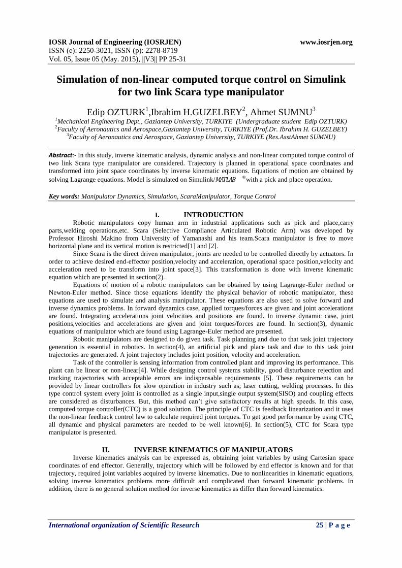
Figure 4-Manipulator Initial Position
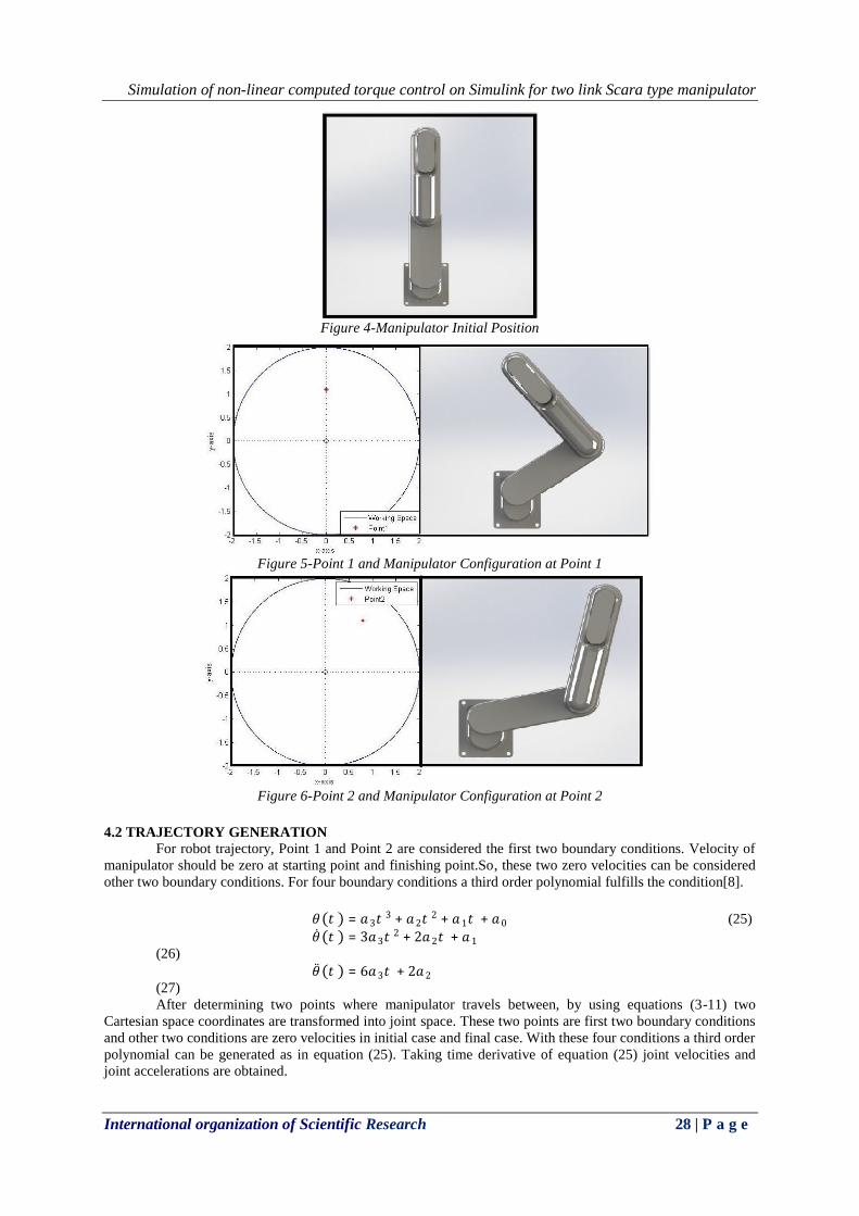
Figure 5-Point 1 and Manipulator Configuration at Point 1
Figure 6-Point 2 and Manipulator Configuration at Point 2
4.2 TRAJECTORY GENERATION For robot trajectory, Point 1 and Point 2 are considered the first two boundary conditions. Velocity of
manipulator should be zero at starting point and finishing point.So, these two zero velocities can be considered
other two boundary conditions. For four boundary conditions a third order polynomial fulfills the condition[8]. 𝜃(𝑡 ) = 𝑎3𝑡
3 + 𝑎2𝑡2 + 𝑎1𝑡 + 𝑎0 (25)
𝜃 (𝑡 ) = 3𝑎3𝑡2 + 2𝑎2𝑡 + 𝑎1
(26) 𝜃 (𝑡 ) = 6𝑎3𝑡 + 2𝑎2
(27) After determining two points where manipulator travels between, by using equations (3-11) two
Cartesian space coordinates are transformed into joint space. These two points are first two boundary conditions
and other two conditions are zero velocities in initial case and final case. With these four conditions a third order
polynomial can be generated as in equation (25). Taking time derivative of equation (25) joint velocities and
joint accelerations are obtained.
Simulation of non-linear computed torque control on Simulink for two link Scara type manipulator
International organization of Scientific Research 29 | P a g e
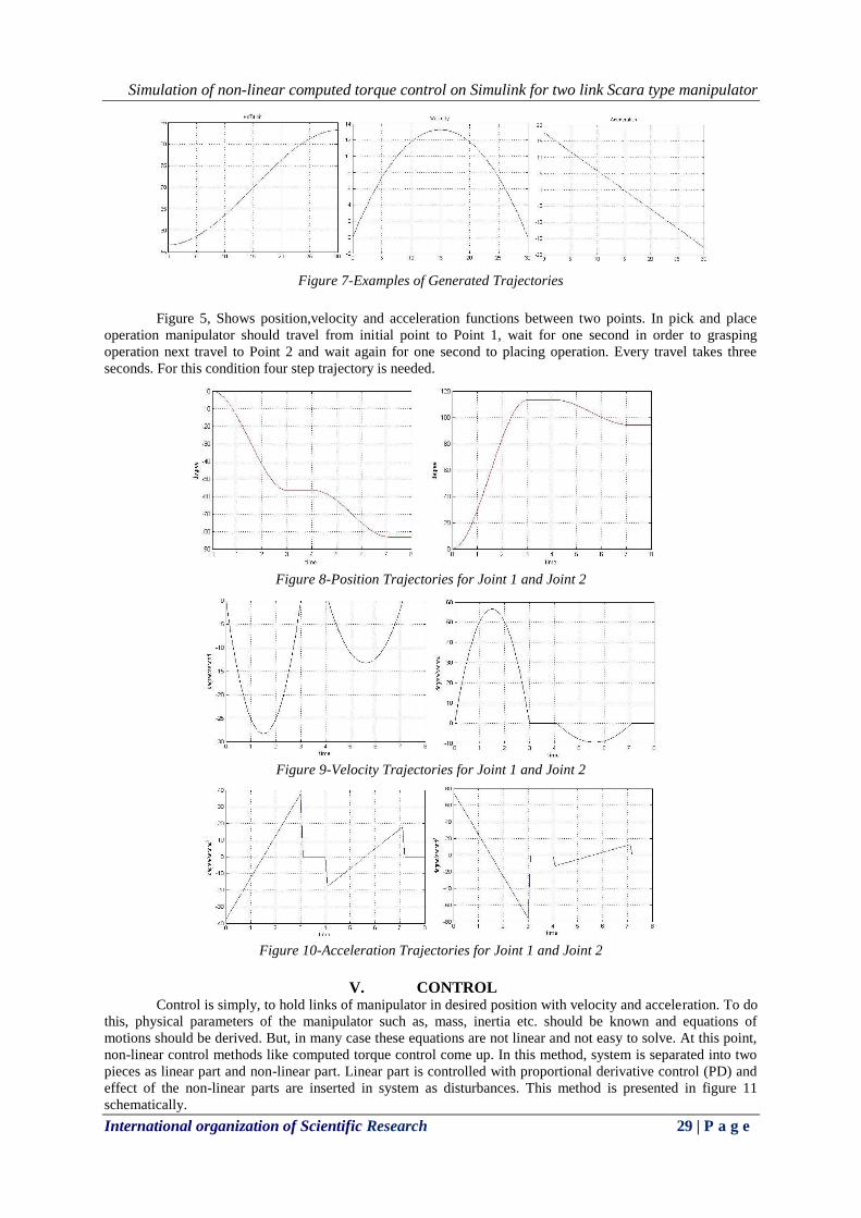
Figure 7-Examples of Generated Trajectories
Figure 5, Shows position,velocity and acceleration functions between two points. In pick and place
operation manipulator should travel from initial point to Point 1, wait for one second in order to grasping
operation next travel to Point 2 and wait again for one second to placing operation. Every travel takes three
seconds. For this condition four step trajectory is needed.
Figure 8-Position Trajectories for Joint 1 and Joint 2
Figure 9-Velocity Trajectories for Joint 1 and Joint 2
Figure 10-Acceleration Trajectories for Joint 1 and Joint 2
V. CONTROL
Control is simply, to hold links of manipulator in desired position with velocity and acceleration. To do
this, physical parameters of the manipulator such as, mass, inertia etc. should be known and equations of
motions should be derived. But, in many case these equations are not linear and not easy to solve. At this point,
non-linear control methods like computed torque control come up. In this method, system is separated into two
pieces as linear part and non-linear part. Linear part is controlled with proportional derivative control (PD) and
effect of the non-linear parts are inserted in system as disturbances. This method is presented in figure 11
schematically.

Simulation of non-linear computed torque control on Simulink for two link Scara type manipulator
International organization of Scientific Research 30 | P a g e
𝑒 (𝑡 ) = 𝑞 𝑑(𝑡 ) − 𝑞 𝑎 (𝑡 ) (28) Where e(t) is the error function, 𝑞 𝑑(𝑡 ) is the desired path and 𝑞 𝑎(𝑡 ) is the actual path. 𝑉(𝑞 , 𝑞 ) + 𝐺(𝑞) = 𝑁(𝑞 , 𝑞 )
(29) Dynamic equation of manipulator becomes; 𝑀(𝑞)𝑞 + 𝑁(𝑞 , 𝑞 ) = 𝜏 (30) PD control scheme can be written as; 𝑢(𝑡 ) = −𝐾𝐷𝑒 − 𝐾𝑃𝑒 (31)
Figure11- Control Scheme
𝐾𝐷 𝑎𝑛𝑑 𝐾𝑝are diagonal gain matrices of proportional and derivative gains respectively. Equation (30) becomes; 𝜏 = 𝑀(𝑞)(𝑞 𝑑 + 𝐾𝐷𝑒 + 𝐾𝑃𝑒 ) + 𝑁(𝑞 ,𝑞 ) (32) Resulting linear error dynamics is; (𝑞 𝑑 + 𝐾𝐷𝑒 + 𝐾𝑃𝑒 ) = 0 (33) Considering linear system theory, tracking error converges to zero[3].
Figure 12-Computed Torque Block Diagram[9]
VI. DISCUSSION AND CONCLUSION During simulation, link lengths L1 and L2 were considered 1 meter, initial position of the manipulator
is at P(x,y)=P(0,2). Operational space of manipulator is simply a circle with a diameter of four meters. Picking
operation point was chosen P(0,1.1) and placing point P(0.8,1.1). Simulation time was eight seconds, between
Simulation of non-linear computed torque control on Simulink for two link Scara type manipulator
International organization of Scientific Research 31 | P a g e
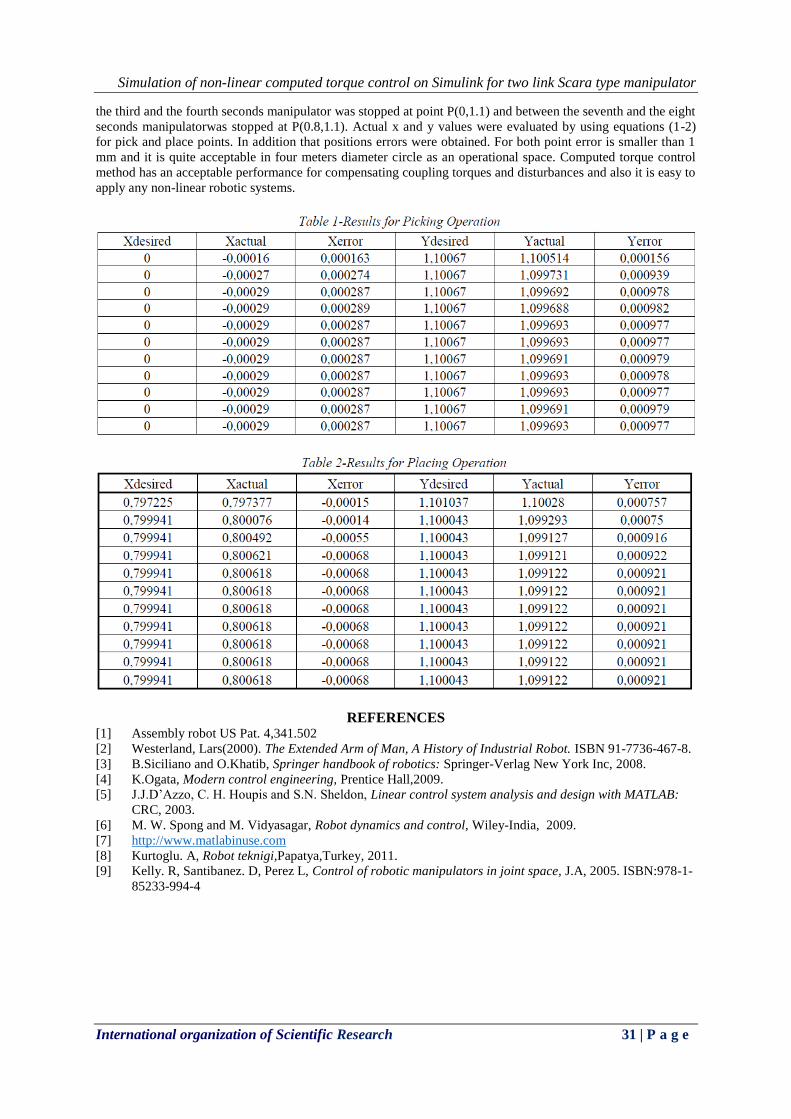
the third and the fourth seconds manipulator was stopped at point P(0,1.1) and between the seventh and the eight
seconds manipulatorwas stopped at P(0.8,1.1). Actual x and y values were evaluated by using equations (1-2)
for pick and place points. In addition that positions errors were obtained. For both point error is smaller than 1
mm and it is quite acceptable in four meters diameter circle as an operational space. Computed torque control
method has an acceptable performance for compensating coupling torques and disturbances and also it is easy to
apply any non-linear robotic systems.
REFERENCES [1] Assembly robot US Pat. 4,341.502 [2] Westerland, Lars(2000). The Extended Arm of Man, A History of Industrial Robot. ISBN 91-7736-467-8. [3] B.Siciliano and O.Khatib, Springer handbook of robotics: Springer-Verlag New York Inc, 2008. [4] K.Ogata, Modern control engineering, Prentice Hall,2009. [5] J.J.D’Azzo, C. H. Houpis and S.N. Sheldon, Linear control system analysis and design with MATLAB:
CRC, 2003. [6] M. W. Spong and M. Vidyasagar, Robot dynamics and control, Wiley-India, 2009. [7] http://www.matlabinuse.com [8] Kurtoglu. A, Robot teknigi,Papatya,Turkey, 2011. [9] Kelly. R, Santibanez. D, Perez L, Control of robotic manipulators in joint space, J.A, 2005. ISBN:978-1-
85233-994-4