denon stereo cd player dcd-485-dcd-685 parts and service manual
DESCRIPTION
Service ManualTRANSCRIPT

BSERVICE MANUAL
Some illustration using in this service manual is slightly from the actual set.
MODEL
DCD-485/685
STEREO CD PLAYER
DCD-485
DCD-685
Hi-Fi Component

2
SAFETY PRECAUTIONS
SPECIFICATIONS
SAFETY PRECAUTIONS
The following check should be performed for the continued prtection of the customer and service technician.
LEAKAGE CURRENT CHECK
Before reterning the unit to the customer,make sure you make either (1) aleakage current check or (2) a line to chassis resistance check. If the leakage current exceeds 0.5 miliamps, or if hte resistance from chassis to either side of the power cord is less than 460 kohms, the unit is detective.
AUDIO
DCD-485
DISCS
REMOTE CONTROL UNIT
FUNCTIONS AND DISPLAY
GENERAL CHARACTERISTICS
434 (W) x 100 (H) x 285 (D) mm
2 channels
Dimensions:
54.5 (W) x 140 (H) x 24.8 (D) mmExternal Dimensions:
Number of Channels:
Automatic searchi, programmed playback, repeat playback, manual search, auto space,time mode, auto edit, dimmer, random playback, pitch control (DCD-685 only)
Functions:
Remote Control System:
Track number, time, music calendar and engaged modesDisplay:
Headphones jack
Infrared pulse systemRC-266
Others:
Mass: 3.4 kg
Mass: 85 g including batteries
AC 230 V, 50 Hz Power Supply:
3V DC; two R6P (standard size AA) dry cell batteriesPower Supply:
Power consumption: 11 W
2 to 20 kHzFreqency Responese:
0.2 to 2.0 VOutput Voltage:
98 dB105 dB
Dynamic Range:
Signal to Noise ratio:
0.003 % (1 kHz)Harmonic distortion:
102 dB (1 kHz)Separation:
Below measurable limit:
Compact Disc format
( 0.001 % W. peak)
3.6 kg
12 W
100 dB110 dB
103 dB (1 kHz)Wow and Flutter:
✽ Specifications and design are subject to change without notice for purpose of improvement.
SPECIFICATIONS
DCD-685

3
DISASSENBLY
Follow the procedure below in reverse order when reassembling(Follow the procedure below in reverse order when reassembling)
1. Top Cover1. Remove 4 screws 1 on both sides.2. Remove 2 screws 2 on the Rear Panel.3. Detach the Top Cover as shown in the fig.
2. Front Panel1. Remove 1 screw 3 on the Rear Panel and 1 screw 4 fixing Support Bracket (b). (only DCD-485)2. Take off the Mecha Cover after removing 2 screws 5 .
Open the Tray by turning the Gear (a) clockwise,then detach the Loader Panel.
3. Remove 3 screws 6 on the bottom edge of theFront Panel.
4. Remove 2 screws 7 , at L/R ends of the Front
Panel and 1 screw 8 fixing Phone P.W.B.
Support Bracket

4
4. Main P.W.B.1. Remove 5 screws 10 , 5 screws 11 on the Rear
Panel and detach it.2. Remove 3 screws 12 fixing the Main P.W.B.3. Unfasten 1 P.W.B. Holder to detach the Main
P.W.B.
4. Remove 1 screw and 2 screw fixing the
Power P.W.B.5. Unfasten 1 P.W.B. Holder to detach the Power
P.W.B.
3. CD Mecha. Unit
1. Remove 4 screws 9 fixing the CD Mecha.2. Unplug Connectors (b), (c) and FFC from each
socket.3. Release the FFC from the Clamper.

5
CD TEST MODE
Setting of the test mode
How to start the test mode: Turn on the power in the condition that CLOSE (Pin No. 3 )
and OPEN (Pin No. 4 ) of CX053 are being shorted. ( “01” is indicated on the DISPLAY)
To exit from the test mode, turn off the power. (Refer to Fig. 1 “Test Point Layout”)
Fig. 1 “Test Point” Layout
* Laser light of the pickup is always emitted regardless of DISC loading in the test mode.
You may lose your eyesight if you look into the laser directly.
So be careful enough when operating in the test mode.
Used DISC: A-BEX TCD784
Explanation of each button
* Use only the buttons described below for operations while in the test mode,
and don’t push any other buttons.
Names of buttons Operation
OPEN / CLOSE * Loads or unloads DISC
PLAY * Emits laser light * Repeats search operation (No DISC condition: While it’s pressed) * Actuates focus servo (In case of DISC loaded) * Actuates tracking servo
STOP * Stops operation
PAUSE * Performs auto adjustment
MANUAL SEARCHFORWARD / REVERSE
* Moves pickup

6
How to check the test mode
( 1 ) DISC discrimination, adjustment
* Insert DISC, and press the PAUSE button.
* “06 Adj” is displayed, and discrimination of DISC size 8 cm/12 cm, discrimination of
DISC reflectance (CD, CD-R/CD-RW), adjustment of focus, tracking offset,
and EF balance will be performed. (Adjusted values are not displayed: Refer to Fig. 2, 3)
Fig. 2 DISC discrimination, adjustment Fig. 3
(Case of CD-RW) Adjustment of EF balance
* After completing the discrimination and adjustment, it becomes stop condition.
* Once discrimination of DISC has been carried out in the “06 Adj” mode, discrimination of
size and reflectance is no longer made, and only adjustment will be performed.
( 2 ) Checking of servo state
* Press the PLAY button after performing above (1) “DISC discrimination, adjustment”.
* “02 L on” is displayed, and the laser will start to light. (The pickup may vibrate with a rattling
noise if DISC has been loaded, but this is not abnormal.)
* Press the PLAY button again.
* “03 F on”is displayed. DISC starts turning,and focus servo will be actuated. (Refer to Fig. 4, 5)
FEO
TEO
HF
DRF
TEO
TB
SLD
FEO
TEO
TEO
HF
7
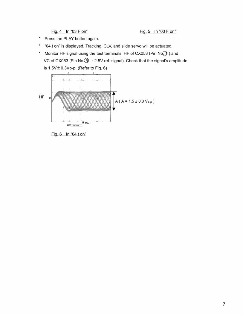
Fig. 4 In “03 F on” Fig. 5 In “03 F on”
* Press the PLAY button again.
* “04 t on” is displayed. Tracking, CLV, and slide servo will be actuated.
* Monitor HF signal using the test terminals, HF of CX053 (Pin No. 1 ) and
VC of CX063 (Pin No. 5 : 2.5V ref. signal). Check that the signal’s amplitude
is 1.5V 0.3Vp-p. (Refer to Fig. 6)
Fig. 6 In “04 t on”
A ( A = 1.5 ± 0.3 VP-P )HF

8
Wave-forms of each point
SPD
SPD
FEO
TEO
DRF
HF
SLD
TEO
SLD
OPEN
CLOSE
SPD
SPD
TD
TEO
HF
DRF
SLD
TEO
FD
When 12 cm DISC
start
When 8 cm DISC
start
When focus servo
on
Track search
(when forward)
During PLAY
When the tray
OPEN
When 12 cm DISC
stop
When 8 cm DISC
stop
During PAUSE
Track search
(when reverse)
Focus search
(no DISC)
p

9
BLOCK DIAGRAM
DC
D-6
85
on
lyD
CD
-48
5 o
nly
DC
D-6
85
on
ly
RW
SW
FO
CU
SC
OIL
Drv
.
TR
AC
KIN
GC
OIL
Drv
.
SLID
EM
tr.
Drv
.
SP
IND
LE
Mtr
Drv
.
LO
AD
ING
Mtr
. D
rv.
LA
6995
IC104
PIC
KU
P
FO
CU
SC
OIL
TR
AC
KIN
CO
IL
M
SLID
E
M
SP
IND
LE
M
LO
AD
ING
L.D
IOD
E
CD
ME
CH
AK
SL-2
130C
CM
INM
OS
T-S
W
OP
EN
-SW
CLO
SE
-SW
AS
PLA
9241
M
IC101
DS
PLC
78
625
E
IC102
H/P
AM
PIC
315
DA
CP
CM
1702
IC602/6
03
D.F
ILT
ER
SM
5841B
SIC
703 µ-C
OM
µP
D78
044F
IC201
1U
-33
46
-1
MA
IN U
NIT
MU
TE
MU
TE
DR
F
SL
SUBCODE
CD
/RW
A/D
IN
PU
T
FSEQ
KE
YM
AT
RIX
VF
DF
L601
RE
MO
TE
SE
NS
OR
IC702
OP
T.O
UT
1U
-3346-4
H/P
UN
IT
CO
TR
OL B
US
1U
-334
6-3
DIS
PLA
Y
V R
1U
-3346-2
PO
WE
RU
NIT
RO
TA
LY
EN
CO
DE
RS
616
CY
271
CX
271
±8V
-HB
+V
DD
CONTROL
XRST2
DF
&D
AC
PC
M1735
IC105
VC
OT
C9246F
IC108 XRST1
D.MUTE
MD2
LD
ON
PO
WE
R C
ON
T.
M5290P
IC501
PO
WE
R
TR
AN
S.
PT
501
AC
INLE
T
PO
WE
R S
W
1U
-3346-5
±5V
RE
SE
T
MU
TE
CO
NT
RO
L
PLL
BU
2616F
IC107
CO
NT
RO
L
DR
V.M
UT
E

10
NOTE FOR HANDLING OF LASER PICK-UP
Description of the Components
Label
Pin Connector
year(last figure)
day month quality control No.
Lot No.
lop No.
Oct. Nov. and Dec. are expressed by alphabetical letters of X, Y and Z.
10 1 10-1
LD drive currentquality control
The expressed unit is by mA, with omission of the decimal point as for example, 56.5mA will be ex-pressed as 565, but the head of English letter meansthe control in the manufacturning plant.
Pin No. Description IN/OUT
1 PD IC Vc IN
2 Vcc IN
3 E OUT
4 D OUT
5 A OUT
6 B OUT
7 C OUT
8 F OUT
KSS-213CLot No.
lop
Slide rack
OP Slide base
Object Lens Actuator cover
PAL-2 Flexible board
Label
Flexible flat cable connector
Z-axis
Y-axis(Tangental direction)
X-axis(Radial direction)
+Z-axis direction
+X-axis direction
+Y-axis direction
1 3 5 7 9 11 13 152 4 6 8 10 12 14 16
KSS-213C
Flexible flat cable connector
Pin No. Description IN/OUT
9 GND IN
10 LD LD IN
11 VR IN
12 PD OUT
13 FCS (+) IN
14 TRK (+) IN
15 TRK (−) IN
16 FCS (−) IN
LDPDIC
1413121110987654321 1615
TRACKING
LDPDIC
+2.5V +5V
SHORT LAND
FOCUSING
CAUTION: The soldered connecting portion must be bridged when removing CX161.

11
Caution for Handling the Laser Pick-up
The laser pick-up KSS-213C is assembled and preciselyadjusted using a sophisticated manufacturing process in ourplant. Do not disassemble or attempt to readjust it. Pleaseobserve the following instructions carefully in handling thepick-up.
1. Handle with Care
(1) StorageDo not store the pick-up in dusty, high-temperatured orhigh-humidity environments.
(2) Please take care for preventing from shock by fallingdown or careless handling.
2. Laser Diode (LD)
(1) Protect your eyesThe laser beam may damage the human eye, since theintensity of the focused spot may reach 7×10³
W/cm2 even if the intensity at the objective lens is 400µWmaximum. As the light beam spreads after focusedthrough the objective lens, it does not effect you in theplace as far as more than 30 cms. However, do not lookat the laser light beam either through the objective lensdirectly nor another lens or a mirror.
(2) Poison of AsSince the LD chip contains As (Arsenic), as GaAs +GaAlAs, as known as the poison, although the poison isrelatively weak, in comparing with others, e.g. As2O3,AsCl3 etc., and the amount is small, avoid putting thechip in acid or an alkali solution, heating it over 200 °Cor putting it into your mouth.
(3) Avoid surge current or electrostatic dischargeThe LD may be damaged or deteriorated by its ownstrong light if a large current is supplied to it, even if onlya short pulse.Make sure that there is no surge current in the LD drivingcircuit by switches or else. Be careful to handle pick-upas it may be damaged in a moment by humanelectrostatic discharge. The pins of the LD are short-circuited by solder for protection during shipment.For safety handling of an LD, grounding the human body,measuring equipments and jig is strongly recommended.And still it is further desirable to make use of mat on theplatform and floor for handling the LD.To open the short-circuit, remove the soldering quicklywith a soldering iron whose metal part is grounded.The temperature of the soldering iron should be less than320°C (30W).
3. Actuator
(1) The performance of the actuator may be affected ifmagnetic material is located nearby, since the actuatorhas a strong magnetic circuit. Do not permit dust to enterthrough the clearance of the cover.
(2) Cleaning the lensIt may change the specifications by attaching dust orash on the objective lens. Clean the lens with a cleaningpaper dampened with, not pressing lens with so muchstrength by the cleaning paper.
4. Metal Bearing
As the metal bearing of Cu-compound sintered alloy isimpregnated with FROIL946P, never fail to supply thebushing with the same lubricant at the time of replacing thepick-up.
5. Handling
Please handle the laser pick-up with holding the slide base.(resin molded part).When either a part of human body or some other things mayhappen to touch directly with the circuit part of P.W.Board, itmay cause deterioration, take careful attention in handlingthis base.
6. Deterioration
As KSS-213C comprises built-in RF Amp and APC circuit,resists stronger against external electrostatic damages thanthe former typed pickup. However, there is possibility ofpickup deterioration in the following cases.(1) Low HF level, or with great numbers of jitters.(2) Tracking offset (EF Balance) is out of order (Refer to
“Confirmation Method of Adjustment”for confirmation (1)and (2)).

12
SEMICONDUCTORS
µPD78044FGF-188-3B9 (IC601)
1
24
25
4041
64
65
80
64 63 62 61 60 59 58 57 56 55 54 53 52 51 50 49 48 47 46 45 44 43 42 41
1 2 3 4 5 6 7 8 9 10 11 12 13 14 15 16 17 18 19 20 21 22 23 24
40
39
38
37
36
35
34
33
32
31
30
29
28
27
26
25
65
66
67
68
69
70
71
72
73
74
75
76
77
78
79
80
PD78044FGF-188-3B9
P113/FIP21
P112/FIP20
P111/FIP19
P110/FIP18
P107/FIP17
P106/FIP16
VLOAD
P105/FIP15
P104/FIP14
P103/FIP13
P102/FIP12
P101/FIP11
P100/FIP10
P197/FIP9
P196/FIP8
P195/FIP7
P33/TI1
P34/TI1
P35/PCL
P36/BUZ
P37
X2
X1
Vss
XT2
P04/XT1
AVRES
AVDD
P10/AN10
P11/AN11
P12/AN12
P13/AN13
P11
4/F
IP22
P11
5/F
IP23
P11
6/F
IP24
P11
7/F
IP25
P12
0/F
IP26
P12
1/F
IP27
P12
2/F
IP28
P12
3/F
IP29
P12
4/F
IP30
P12
5/F
IP31
P12
6/F
IP32
P12
7/F
IP33
V DD
P70
P71
P72
IC (
Vpp
)
PO
O/IN
TP
O/T
10
PO
1/IN
TP
1
PO
2/IN
TP
2
P03
/INT
P3/
C10
P31
/TO
0
P31
/TO
1
P32
/TO
2
P94
/FIP
6
P93
/FIP
5
P92
/FIP
4
P91
/FIP
3
P90
/FIP
2
P81
/FIP
1
P80
/FIP
0
VD
D
P27
/SC
K0
P26
/SO
0/S
B1
P25
/SIO
/SB
O
P24
/BU
SY
P23
/ST
B
P22
/SC
K1
P21
/SO
1
P20
/SI1
RE
ST
P74
P73
AV
ss
P17
/AN
17
P16
/AN
16
P15
/AN
15
P14
/AN
14
1 P94/FIP6 NC O C Hz − − − Not used (Open)
2 P93/FIP5 6G O C Hz L H P. D VFD grid 6G (EMPHASIS, PLAY, PAUSE,REPEAT)
3 P92/FIP4 5G O C Hz L H P. D VFD grid 5G (11~20, A-B, PROG, )
4 P91/FIP3 4G O C Hz L H P. D VFD grid 4G (1~10)
5 P90/FIP2 3G O C Hz L H P. D VFD grid 3G (Seconds Digit, S, SINGLE)
6 P81/FIP1 2G O C Hz L H P. D VFD grid 2G (Minutes Digit, M, TOTAL)
7 P80/FIP0 1G O C Hz L H P. D VFD grid 1G (Track No., A.SPACE)
8 VDD VDD − − − − − − Positive power (Connect to +5V)
9 P27/SCK0 MCK O B Hz H P. UP SM5841/PCM1735/BU2616 mode control clock output
10 P26/S00/SB1 MDT O B Hz − − P. UP SM5841/PCM1735/BU2616 mode control data output
11 P25/SI0/SB0 NC I B Hz − − P. DG Not used (Connect to GND)
12 P24/BUSY NC I B Hz − − P. DG Not used (Connect to GND)
13 P23/STB MLE O B Hz − P. UP SM5841/PCM1735 mode control latch output
14 P22/SCK1 CQCK O B Hz − − DSP, ASP Command clock & SUBQ readout clock output
15 P21/SO1 COIN O B Hz − − − DSP, ASP Command data output
16 P20/SI1 SUBQ I B Hz − − − DSP sub-code Q data input
17 RESET RESET I − − − L − Reset signal input
18 P74 NC I B Hz − − P. DG Not used (Connect to GND)
19 P73 XTAL O B Hz H L P. UP TC9246XTAL MODE change Lo:ON (Pitch 0),Hi:OFF(Variable pitch)
20 AVss AVss − − − − − − GND for A/D converter
21 P17/ANI7 DSP XRST O B Hz L L P. DG DSP reset signal output
22 P16/ANI6 DF XRST O B Hz L L P. DG Digital filter reset signal output
23 P15/ANI5 JOG B I B Hz − − P. UP Rotaly encoder JOG B input
24 P14/ANI4 JOG A I B Hz − − P. UP Rotaly encoder JOG A input
25 P13/ANI3 AD3 I B Hz − A P. UP Key data input 3 (A/D)
26 P12/ANI2 AD2 I B Hz − A P. UP Key data input 2 (A/D)
27 P11/ANI1 AD1 I B Hz − A P. UP Key data input 1 (A/D)
28 P10/ANI0 AD0 I B Hz − A P. UP Key data input 0 (A/D)
29 AVDD AVDD − − − − − − A/D converter analog power (Connect to +5V)
30 AVREF AVREF I − − − − − A/D converter Ref. V input (Connect to +5V)
PinNo.
Terminal Port I/O Typ Rst Ini Act Ext Function
µPD78044FGF-188-3B9 Terminal Function
IC's
13
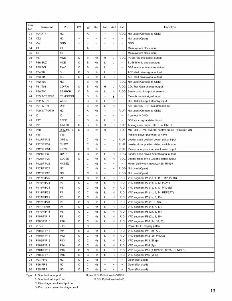
PinNo. Terminal Port I/O Typ Rst Ini Act Ext Function
31 P04/XT1 NC I A − − − P. DG Not used (Connect to GND)
32 XT2 NC − − − − − − Not used (Open)
33 Vss GND − − − − − − GND
34 X1 X1 I A − − − − Main system clock input
35 X2 X2 − − − − − − Main system clock input
36 P37 MCS O B Hz H L P. DG PCM1735 chip select output
37 P36/BUZ MCE O B Hz L L − BU2616 chip enableoutput
38 P35/PCL RWC O B Hz L L − DSP read / write control output
39 P34/TI2 SL+ O B Hz L H − ASP sled drive signal output
40 P33/TI1 SL- O B Hz L H − ASP sled drive signal output
41 P32/T02 NC I B Hz − − P. DG Not used (Connect to GND)
42 P31/T01 CD/RW O B Hz H L P. DG CD / RW Gain change output
43 P30/T00 SEARCH O B Hz L H P. DG Servo control output at search
44 P03/INTP3/CI0 REMOCON I B Hz − − Remote control signal input
45 P02/INTP2 WRQ I B Hz L H − DSP SUBQ output standby input
46 P01/INTP1 DRF I B Hz L H − ASP DEFECT RF level detect input
47 P00/INTP0/TI0 NC I A Hz − − P. UP Not used (Connect to GND)
48 IC IC − − − − − − Connect to GND
49 P72 FSEQ I B Hz L H − DSP sync signal detect input
50 P71 A.MUTE O B Hz H H P. UP Analog mute output OFF: Lo, ON: Hi
51 P70 DRV.MUTE O B Hz H − P. UP MOTOR DRIVER MUTE control output Hi:Output ON
52 VDD VDD − − − − − − Positive power (Connect to +5V)
53 P127/FIP33 OPSW I C Hz − L P. UP Loader open position detect switch input
54 P126/FIP32 CLSW I C Hz − L P. UP Loader close position detect switch input
55 P125/FIP31 INSW I C Hz − L P. UP Pickup inner position detect switch input
56 P124/FIP30 OPEN O C Hz L H P. DG Loader open drive LA6559 signal output
57 P123/FIP29 CLOSE O C Hz L H P. DG Loader close drive LA6559 signal output
58 P122/FIP28 MODEL I C Hz − − − Model distinction input Lo:455, Hi:555
59 P121/FIP27 NC I C Hz − − P. DG Not used (Open)
60 P120/FIP26 NC I C Hz − − P. DG Not used (Open)
61 P117/FIP25 P1 O C Hz L H P. D VFD segment P1 (1a, 1, 11, EMPHASIS)
62 P116/FIP24 P2 O C Hz L H P. D VFD segment P2 (1b, 2, 12, PLAY)
63 P115/FIP23 P3 O C Hz L H P. D VFD segment P3 (1c, 3, 13, PAUSE)
64 P114/FIP22 P4 O C Hz L H P. D VFD segment P4 (1d, 4, 14, REPEAT)
65 P113/FIP21 P5 O C Hz L H P. D VFD segment P5 (1e, 5, 15)
66 P112/FIP20 P6 O C Hz L H P. D VFD segment P6 (1f, 6, 16)
67 P111/FIP19 P7 O C Hz L H P. D VFD segment P7 (1g, 7, 17)
68 P110/FIP18 P8 O C Hz L H P. D VFD segment P8 (2a, 8, 18)
69 P107/FIP17 P9 O C Hz L H P. D VFD segment P9 (2b, 9, 19)
70 P106/FIP16 P10 O C Hz L H P. D VFD segment P10 (2c, 10, 20)
71 VLOAD -HB I C − − − − Power for FL display (-HB)
72 P105/FIP15 P11 O C Hz L H P. D VFD segment P11 (2d, A-B)
73 P104/FIP14 P12 O C Hz L H P. D VFD segment P12 (2e, PROG)
74 P103/FIP13 P13 O C Hz L H P. D VFD segment P13 (2f, )
75 P102/FIP12 P14 O C Hz L H P. D VFD segment P14 (2g)
76 P101/FIP11 P15 O C Hz L H P. D VFD segment P15 (A.SPACE, TOTAL, SINGLE)
77 P100/FIP10 P16 O C Hz L H P. D VFD segment P16 (M, S)
78 P97/FIP9 NC O C Hz − − − Open (Not used)
79 P96/FIP8 NC O C Hz − − − Open (Not used)
80 P95/FIP7 NC O C Hz − − − Open (Not used)
Type A: Standard input port Note) P.D: Pull−down to VDISP
B: Standard in/output port P.DG: Pull−down to GND
C: Hi−voltage proof in/output port
D: P−ch open drain hi−voltage proof
14
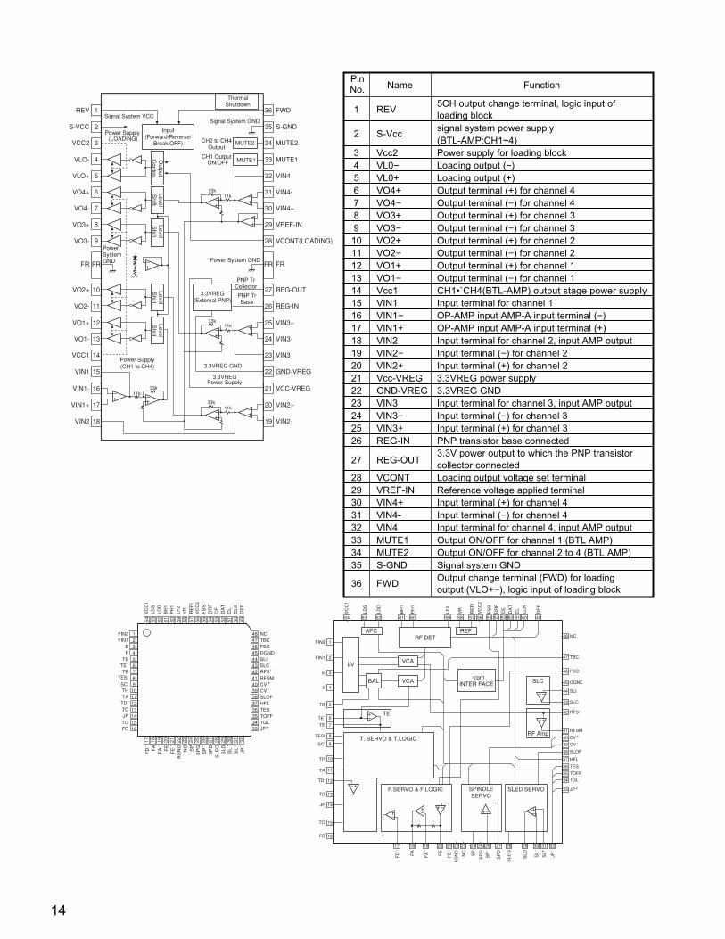
1 REV5CH output change terminal, logic input ofloading block
2 S-Vccsignal system power supply(BTL-AMP:CH1~4)
3 Vcc2 Power supply for loading block4 VL0− Loading output (−)5 VL0+ Loading output (+)6 VO4+ Output terminal (+) for channel 47 VO4− Output terminal (−) for channel 48 VO3+ Output terminal (+) for channel 39 VO3− Output terminal (−) for channel 310 VO2+ Output terminal (+) for channel 211 VO2− Output terminal (−) for channel 212 VO1+ Output terminal (+) for channel 113 VO1− Output terminal (−) for channel 114 Vcc1 CH1•`CH4(BTL-AMP) output stage power supply15 VIN1 Input terminal for channel 116 VIN1− OP-AMP input AMP-A input terminal (−)17 VIN1+ OP-AMP input AMP-A input terminal (+)18 VIN2 Input terminal for channel 2, input AMP output19 VIN2− Input terminal (−) for channel 220 VIN2+ Input terminal (+) for channel 221 Vcc-VREG 3.3VREG power supply22 GND-VREG 3.3VREG GND23 VIN3 Input terminal for channel 3, input AMP output24 VIN3− Input terminal (−) for channel 325 VIN3+ Input terminal (+) for channel 326 REG-IN PNP transistor base connected
27 REG-OUT3.3V power output to which the PNP transistorcollector connected
28 VCONT Loading output voltage set terminal29 VREF-IN Reference voltage applied terminal30 VIN4+ Input terminal (+) for channel 431 VIN4- Input terminal (−) for channel 432 VIN4 Input terminal for channel 4, input AMP output33 MUTE1 Output ON/OFF for channel 1 (BTL AMP)34 MUTE2 Output ON/OFF for channel 2 to 4 (BTL AMP)35 S-GND Signal system GND
36 FWDOutput change terminal (FWD) for loadingoutput (VLO+−), logic input of loading block
PinNo. Name Function
LA9241M (IC103)
1
2
3
4
5
6
7
8
9
FR
10
11
12
13
14
15
16
17
18
36
35
34
33
32
31
30
29
28
FR
27
26
25
24
23
22
21
20
19
FWD
S-GND
MUTE2
MUTE1
VIN4
VIN4-
VIN4+
VREF-IN
VCONT(LOADING)
FR
REG-OUT
REG-IN
VIN3+
VIN3-
VIN3
GND-VREG
VCC-VREG
VIN2+
VIN2-
REV
S-VCC
VCC2
VLO-
VLO+
VO4+
VO4-
VO3+
VO3-
FR
VO2+
VO2-
VO1+
VO1-
VCC1
VIN1
VIN1-
VIN1+
VIN2
Signal System VCC
(CH1 to CH4)
33k11k
33k11k
3.3VREG GND
3.3VREG
33k11k
3.3VREG PNP TrBase
PNP TrCollector
33k11k
CH1 OutputON/OFF
CH2 to CH4Output
MUTE1
MUTE2(LOADING)
Power Supply Input(Forward/Reverse/
Break/OFF)
Output
Control
LevelS
hiftLevelS
hift
PowerSystemGND
LevelS
hiftLevelS
hift
Power Supply
Power Supply
(External PNP)
Power System GND
Signal System GND
ThermalShutdown
NCTBCFSCDGNDSLISLCRFSRFSMCVCVSLOFHFLTESTOFFTGLJP
FD F
AF
A FE
FE
AG
ND
NC
SP
SP
GS
PS
PD
SLE
QS
LD SL
SL
JP
FIN2FIN1
EF
TBTETE
SCITHTA
TDTDJP
TESI
TOFD
64 63 62 61 60 59 58 57 56 55 54 53 52 51 50 49
48474645444342414039383736353433
17 18 19 20 21 22 23 24 25 26 27 28 29 30 31 32
123456789
10111213141516
VC
C1
LDS
LDD
BH
1P
H1
LF2
VR
RE
FI
VC
C2
FS
SD
RF
CE
DA
TC
LC
LKD
EF
-
-
+ ------
+
-+
-
1
2
3
4
5
6
7
8
9
10
11
12
13
14
15
16
17 18 19 20 21 22 23 24 25 26 27 28 29 30 31 32
33
34
35
36
37
38
39
40
41
42
43
44
45
46
47
48
49505152535455565758596061626364
APCRF DET
REF
I/V VCA
VCABAL-com
INTER FACE
T. SERVO & T.LOGIC
F.SERVO & F.LOGIC SPINDLESERVO
SLED SERVO
TE
SLC
RF Amp
FIN2
FIN1
E
F
TB
TE
TE
SCI
TH
TA
TD
TD
JP
TESI
TO
FD
-
-
FD FA
FA FE
FE
AG
ND
NC
SP
SP
G
SP
SP
D
SLE
Q
SLD SL
SL
JP
+ ------
NC
TBC
FSC
DGND
SLI
SLC
RFS
RFSM
CV
CV
SLOF
HFL
TES
TOFF
TGL
JP+
-
+
-
VC
C1
LDS
LDD
BH
1
PH
1
LF2
VR
RE
FI
VC
C2
FS
S
DR
F
CE
DA
T
CL
CLK
DE
F
LA6559 (IC101)

15
1 LRCK I LRCK clock input (fs)2 DATA I Data input3 BCK I Bit clock input for data4 CLKO O System clock, buffer output
5 XTI I X'tal oscillator connect or ext. clock input6 XTO O X'tal oscillator connect7 DGND − Digital GND8 VDD − Digital power supply +5V9 Vcc2R − Analog power supply +5V10 AGND2R − Analog GND11 EXTR O Rch analog out amp, common12 NC − NC13 VoutR O Rch analog V-out14 AGND1 − Analog GND15 Vcc1 − Analog power supply +5V16 VoutL O Lch analog V-out17 ZEROR O Rch zero-data flag (open drain)18 EXTL O Lch analog out amp, common19 AGND2L − Analog GND20 Vcc2L − Analog power supply +5V21 ZEROL O Lch zero-data flag (open drain)
22 RST I Reset, L:DF and ∆-Σ modulator reset23 CS/IWO I Chip select/Input format select24 MODE I Mode control select (H: Soft, L: Hard)25 MUTE I Mute control
26 MD/DM0 I Mode cont. data/De-emphasis select 127 MC/DM1 I Mode cont. BCK/De-emphasis select 228 ML/IIS I Mode cont. latch/Input format select
PinNo. Name FunctionI/O
PCM1735E Terminal FunctionPCM1735E(for DCD-485 : IC301)
1
2
3
4
5
6
7
8
9
10
11
12
13
14
28
27
26
25
24
23
22
21
20
19
18
17
16
15
LRCK
DATA
BCK
CLKO
XTI
XTO
DGND
VDD
Vcc2R
AGND2R
EXTR
NC
VoutR
AGND1
ML/IIS
MC/DM1
MD/DM0
MUTE
MODE
CS/IWO
RST
ZEROL
Vcc2L
AGND2L
EXTL
ZEROR
VoutL
Vcc1
BU2616F (E2) (for DCD-685 : IC102)
1
2
3
4
5
6
7
8
9
18
17
16
15
14
13
12
11
10
XOUT
XIN
CE
DA
CK
DO
SD
IF IN
P3
Vss
PD2
PD1
VDD
FM IN
AM IN
P2
P1
P0
Reference Divider
Prescaler
Shift Register LatchI/OCTL
Counter
If CountCTL
12bit Main Count
Comparator
PhaseDet
XINXOUT
CECKDA
DO
SD
P0 P1 P2 P3
IF IN
Vss
VDD
PD2
PD1
FM IN
AM IN


17
1
2
3
4
5
6
7
8 9
16
15
14
13
12
11
10
VccCLK
D.COM
DATA
LE
+Vcc
REF DC
SERVO DC
A.COM
A.COM
I/O
BPO DC
VDD
+VDD
NC
NC
A OUTPUT
A INPUT
A+INPUT
V
B OUTPUT
V
B INPUT
B +INPUT
1
2
3
4 5
7
8
6
1
2
3
4
5
6
7
8
9
10
11
22
21
20
19
18
17
16
15
14
13
12
CKSLXT1
XT0
CKO
Vss
(NC)
(NC)
MDT
MCK
MLE
RST
DIN
BCK1LRC1
BCKO
(NC)
(NC)
VDD
WCKO
DOL
DOR
DG
(for DCD-685 : IC321,322)PCM1702P
(for DCD-685 : IC304)SM5841BS PC4570C (IC325)
16 131415 12
6
11
1 23 54
9
10
+
+
+
GND
ON/OFF
V cc
Vcc NC
NC
1
2
3
4
5
6
7
8
16
15
14
13
12
11
10
9
−Vcc
NC
-5V OUT
+Vcc
Collecter Out (+)
NC
ON/OFF
GND
M5290FP (IC502)
Emitter Out (-)
Collector Out (-) Emitter Out (+)
+5V OUT
Emitter Out (+)
Collecter Out (+) OUT (+5V) DELAY
REFERENCE
RESET
BALANCE
Collecter Out (−)Emitter Out (−) OUT (−5V)
ON/OFFCONTROL
REF.VDELAYCIRCUIT
CURRENTLIMITER
CURRENTLIMITER
OVER HEAT PROTECTOR
TC9246F (for DCD-685 : IC104)
16
1
15
2
14
3
13
4
12
5
11
6
10
7
9
8
REF
VAR
Lock DitectionCircuit Microcomputer Interface
VCO SelectorPhaseComparator
Programmable Counter
V LOC
K
S2
S1
M2
M1
CK
O
VssD
DR
EF
AM
PI
AM
PO XI
XOPD
VD
DA
VS
SA
TC7WU04F(IC107)
5
7
8
6
1
2
3
4
1A
3Y
2A
GND
Vcc
1Y
3A
2Y

18
TRANSISTORS
R 2
R 1B
C
E
PNP TYPE
R 2
R 1B
C
E
NPN TYPE
R2
10kohm
R1
10kohmDTC114EK22kohmDTA124XKA 47kohmR1 R2
DIODES
DTA124XKADTA144EK DTC114EKDTC144EKDTC144TK
1SR35-400A
2SB1185 (E/F)2SD1762 (E/F)
2SB562 (C) 2SD2144S 2SA1037K (S/R)2SC3326 (for DCD-485)
PNP TYPE
NPN TYPE
1SS270A MTZJ24AMTZJ6.8AHZS2B-1 (for DCD-685)
DTA144EK 47kohm 47kohm 47kohmDTC144EK 47kohmDTC144TK 47kohm OPEN
OPTICAL TERMINAL
IC PROTECTOR
TOTX179 (JK201)
ICP-N20 (IC503)
B (Base)C (Collector)E (Emitter)
B (Base)C (Collector)E (Emitter)
E (Emitter)C (Collector)B (Base)
Navy Blue
Dark Blue
1
2
3
4 5
6
7
8 V
B OUTPUT
B - INPUT
B +INPUT
+ -
+-
A OUTPUT
A - INPUT
A +INPUT
V
A
B
-
++B
- B
(for DCD-685 : IC323, 324)BA15218F (for DCD-485 : IC303)
2
3
11: E/GND2: B/INPUT3: C/OUTPUT
2
3
1
1: Emitter2: Base/IN3: Collector
123 1. GND2. Vcc3. Input

19
Note: 1) F1, F2 Filament
2) NP No pin
3) P1~P16 Anode
4) 1G~6G Grid
5) NX No extend pin
6) Field of vision is a minimum of 29° from the upper side, 30° from the lower side.
GND Vcc Vout
(Part No. : 393 8021 006)
Pin No.
Connection
1 2 3 4 5 6 7 8 9 10 11 12 13 14 15
16 17 18 19 20 21 22 23 24
P12 P11 P10 P9 P8 P7 P6 P5 P4
F1 F1 NP 1G 2G 3G 4G 5G 6G NX P16
Pin No.
Connection P3
25 26 27 28 29 30
P2 P1
FL DISPLAY 6-ST-33GK
NP F2 F2
P13P14P15
GP1U271X (IC601)
Remote Control Sensor
Pin Connection
Anode Connection
Hysteresis
RL
Compararor
NX
GND
VOUT
Vcc
1G 2G 3G 4G
6G 5G
2a 1a1 1
111d ce
bf 1g2a 1a 2a 1a
1 30
1G 2G 3G 4G 6G5G
P1
P2
P3
P4
P5
P6
P7
P8
P9
P10
P12
P11
P13
P14
P15
P16
1a
1b
1c
1d
1e
1f
1g
2a
2b
2c
2d
2e
2f
2g
1a
1b
1c
1d
1e
1f
1g
2a
2b
2c
2d
2e
2f
2g
1a
1b
1c
1d
1e
1f
1g
2a
2b
2c
2d
2e
2f
2g

PRINTED WIRING BOARDCD BOARD ASS'Y
COMPONENT SIDE
20

COPPER SIDE
21

22
Resistors
Ex.: RN 14K 2E 182 G FRType Shape Power Resist- Allowable Others
and per- ance errorformance
CE : Aluminum foil 0J : 6.3V F : ±1% HS : High stability typeelectrolytic
CA : Aluminum solid 1A : 10V G : ±2% BP : Non-polar typeelectrolytic
CS : Tantalum electrolytic 1C : 16V J : ±5% HR : Ripple-resistant typeCQ : Film 1E : 25V K : ±10% DL : For change and dischargeCK : Ceramic 1V : 35V M : ±20% HF : For assuring high
frequencyCC : Ceramic 1H : 50V Z : +80% U : UL partCP : Oil 2A : 100V –20% C : CSA partCM : Mica 2B : 125V P : +100% W : UL-CSA typeCF : Metallized 2C : 160V –0% F : Lead wire formingCH : Metallized 2D : 200V C : ±0.25pF
2E : 250V D : ±0.5pF2H : 500V = : Others2J : 630V
RD : Carbon 2B : 1/8W F : ±1% P : Pulse-resistant typeRC : Composition 2E : 1/4W G : ±2% NL : Low noise typeRS : Metal oxide film 2H : 1/2W J : ±5% NB : Non-burning typeRW : W inding 3A : 1W K : ±10% FR : Fuse-resistorRN : Metal film 3D : 2W M : ±20% F : Lead wire formingRK : Metal mixture 3F : 3W
3H : 5W
Resistance
1 8 2 ⇒ 1800 ohm = 1.8 kohmIndicates number of zeros after effective number.2-digit effective number.
• Units: ohm
1 R 2 ⇒ 1.2 ohm1-digit effective number.2-digit effective number, decimal point indicated by R.
• Units: ohm
Capacitors
Ex.: CE 04W 1H 2R2 M BPType Shape Dielectric Capacity Allowable Others
and per- strength errorformance
Capacity (electrolyte only)
2 2 2 ⇒ 2200µFIndicates number of zeros after effective number.2-digit effective number.
• Units: µF.
2 R 2 ⇒ 2.2µF1-digit effective number.2-digit effective number, decimal point indicated by R.
• Units: µF.
Capacity (except electrolyte)
2 2 2 ⇒ 2200pF=0.0022µF(More than 2) Indicates number of zeros after effective number.
2-digit effective number.• Units: µF.
2 2 1 ⇒ 220pF(0 or 1) Indicates number of zeros after effective number.
2-digit effective number.• Units: pF.
• When the dielectric strength is indicated in AC, "AC" is included after the dieelectricstrength value.
NOTE FOR PARTS LISTPart indicated with the mark " " are not always in stock and possibly to take a long period of time for supplying, or insome case supplying of part may be refused.When ordering of part, clearly indicate "1" and "I" (i) to avoid mis-supplying.Ordering part without stating its part number can not be supplied.Part indicated with the mark " " is not illustrated in the exploded view.Not including Carbon Film ±5%, 1/4W Type in the P.W.Board parts list. (Refer to the Schematic Diagram for those parts.)
WARNING:
Parts marked with this symbol have critical characteristics.Use ONLY replacement parts recommended by the manufacturer.

23
PARTS LIST OF P.W.B. UNIT ASS'Y
1U-3346 (DCD-485Model) / 1U-3346A (DCD-685Model)
CD BOAD ASS’Y
Ref. No. Part No. Part Name Remarks
SEMICONDUCTORS GROUP
IC101 263 1091 907 IC LA6559 IC102 262 2789 901 IC BU2616F(E2) DCD-685 model onlyIC103 263 1090 005 IC LA9241M IC104 262 1883 905 IC TC9246F-TP1 DCD-685 model onlyIC106 262 2903 004 IC LC78625E IC107 262 1953 903 IC TC7WU04F
IC301 262 2846 909 IC PCM1735E DCD-485 model onlyIC303 263 0615 902 IC BA15218F-DXE2 DCD-485 model onlyIC304 262 1765 900 IC SM5841BS DCD-685 model onlyIC321,322 262 1837 032 IC PCM1702P-L DCD-685 model onlyIC323,324 263 0615 902 IC BA15218F-DXE2 DCD-685 model onlyIC325 262 0864 006 IC UPC4570C
IC502 263 0693 005 IC M5290PIC503 268 0074 904 IC ICP-N20T
IC601 262 2904 003 IC UPD78044FGF-188-3B9 IC602 499 0303 004 IC GP1UM271XK
TR101-104 269 0054 901 Transistor DTC144EKT96TR105 271 0238 908 Transistor 2SA1037KT96(S/R)TR106 274 0120 002 Transistor 2SD1762(E/F)TR108,109 269 0085 909 Transistor DTC144TKT96
TR323,324 274 0160 907 Transistor 2SD2144STPU
TR401,402 274 0160 907 Transistor 2SD2144STPU DCD-685 model onlyTR403,404 273 0348 904 Transistor 2SC3326
A/B (TAPE)
DCD-485 model only
TR501 274 0120 002 Transistor 2SD1762(E/F)TR502 272 0083 004 Transistor 2SB1185(E/F)TR503 272 0025 907 Transistor 2SB562(C)TFTR504 269 0055 900 Transistor DTA144EKT96TR505 269 0082 902 Transistor DTC114EKT96TR506 269 0156 906 Transistor DTA124XKA-T146TR507 269 0082 902 Transistor DTC114EKT96
D502-509 276 0704 903 Diode 1SR35-400A(T93X) D510 276 0432 903 Diode 1SS270A TE (TAPE)
ZD101 276 0644 908 Zener diode MTZJ6.8A T77ZD102 276 0450 901 Zener diode HZS2B-1TD DCD-685 model only
ZD501 276 0644 908 Zener diode MTZJ6.8A T77ZD502 276 0645 936 Zener diode MTZJ24A T77
RESISTORS GROUP
R101 247 2010 969 Carbon chip 22 kohm 1/10W RM73B--223JT R102-105 247 2009 941 Carbon chip 6.8 kohm 1/10W RM73B--682JT R106 247 2010 969 Carbon chip 22 kohm 1/10W RM73B--223JT R107 247 2018 903 Carbon chip 0 ohm 1/10W RM73B--0R0KT R108-110 247 2004 920 Carbon chip 47 ohm 1/10W RM73B--470JT R111 247 2010 969 Carbon chip 22 kohm 1/10W RM73B--223JT R112 247 2004 920 Carbon chip 47 ohm 1/10W RM73B--470JT R113 247 2012 925 Carbon chip 100 kohm 1/10W RM73B--104JT R114 247 2010 956 Carbon chip 20 kohm 1/10W RM73B--203JT R115 247 2009 909 Carbon chip 4.7 kohm 1/10WRM73B--472JT (1608)
Ref. No. Part No. Part Name Remarks
R116 247 2008 926 Carbon chip 2.2 kohm 1/10W RM73B--222JT R117 247 2004 920 Carbon chip 47 ohm 1/10W RM73B--470JT R118 247 2011 984 Carbon chip 68 kohm 1/10W RM73B--683JT R119 247 2010 914 Carbon chip 13 kohm 1/10W RM73B--133JT R120 247 2010 956 Carbon chip 20 kohm 1/10W RM73B--203JT R121 247 2009 909 Carbon chip 4.7 kohm 1/10W RM73B--472JT (1608) R122 247 2009 983 Carbon chip 10 kohm 1/10W RM73B--103JT R123 244 2050 920 Metal oxide 120 ohm 1W(NB)RS14B3A121JNBST(S) R124,125 247 2009 983 Carbon chip 10 kohm 1/10W RM73B--103JT
DCD-685 model onlyR126-128 247 2018 903 Carbon chip 0 ohm 1/106W RM73B--0R0KT
DCD-685 model onlyR129 247 2010 927 Carbon chip 15 kohm 1/10W RM73B--153JT R130 247 2006 986 Carbon chip 560 ohm 1/10W RM73B--561JT R131 247 2018 903 Carbon chip 0 ohm 1/10W RM73B--0R0KT
DCD-685 model onlyR132 247 2010 927 Carbon chip 15 kohm 1/10W RM73B--153JT R133 247 2006 999 Carbon chip 620 ohm 1/10W RM73B--621JT R134 247 2010 969 Carbon chip 22 kohm 1/10W RM73B--223JT R135 247 2011 900 Carbon chip 33 kohm 1/10W RM73B--333JT R136-138 247 2010 969 Carbon chip 22 kohm 1/10W RM73B--223JT R139 247 2013 908 Carbon chip 220 kohm 1/10W RM73B--224JT R140 247 2009 983 Carbon chip 10 kohm 1/10W RM73B--103JT R141,142 247 2010 969 Carbon chip 22 kohm 1/10W RM73B--223JT R143 247 2006 986 Carbon chip 560 ohm 1/10W RM73B--561JT R144 247 2012 909 Carbon chip 82 kohm 1/10W RM73B--823JT R145 247 2011 900 Carbon chip 33 kohm 1/10W RM73B--333JT R146,147 247 2018 903 Carbon chip 0 ohm 1/10W RM73B--0R0KT R148 247 2011 926 Carbon chip 39 kohm 1/10W RM73B--393JT R150 247 2007 985 Carbon chip 1.5 kohm 1/10W RM73B--152JT R151 247 2010 927 Carbon chip 15 kohm 1/10W RM73B--153JT R152 247 2010 972 Carbon chip 24 kohm 1/10W RM73B--243JT R153 247 2010 927 Carbon chip 15 kohm 1/10W RM73B--153JT R154 247 2011 942 Carbon chip 47 kohm 1/10W RM73B--473JT R155 247 2018 903 Carbon chip 0 ohm 1/10W RM73B--0R0KT
DCD-685 model onlyR156 247 2009 967 Carbon chip 8.2 kohm 1/10W RM73B--822JT R158 247 2009 967 Carbon chip 8.2 kohm 1/10W RM73B--822JT R159 247 2018 903 Carbon chip 0 ohm 1/10W RM73B--0R0KT R160 247 2011 926 Carbon chip 39 kohm 1/10W RM73B--393JT R161 247 2010 901 Carbon chip 12 kohm 1/10W RM73B--123JT R162 247 2010 927 Carbon chip 15 kohm 1/10W RM73B--153JT R163 247 2009 925 Carbon chip 5.6 kohm 1/10W RM73B--562JT
DCD-685 model onlyR164 247 2002 964 Carbon chip 10 ohm 1/10W RM73B--100JT R165 247 2018 903 Carbon chip 0 ohm 1/10W RM73B--0R0KT R166 247 2011 942 Carbon chip 47 kohm 1/10W RM73B--473JT R167 247 2018 903 Carbon chip 0 ohm 1/10W RM73B--0R0KT R168 247 2009 941 Carbon chip 6.8 kohm 1/10W RM73B--682JT R169 247 2011 900 Carbon chip 33 kohm 1/10W RM73B--333JT R170 247 2018 903 Carbon chip 0 ohm 1/10W RM73B--0R0KT
DCD-685 model onlyR171,172 247 2009 983 Carbon chip 10 kohm 1/10W RM73B--103JT
DCD-685 model onlyR173 247 2008 926 Carbon chip 2.2 kohm 1/10W RM73B--222JT R174 247 2010 985 Carbon chip 27 kohm 1/10W RM73B--273JT R175 247 2012 912 Carbon chip 91 kohm 1/10W RM73B--913JT
DCD-685 model onlyR176 247 2010 998 Carbon chip 30 kohm 1/10W RM73B--303JT R177 247 2006 931 Carbon chip 360 ohm 1/10W RM73B--361JT R178 247 2011 913 Carbon chip 36 kohm 1/10W RM73B--363JT R179 247 2012 954 Carbon chip 130 kohm 1/10W RM73B--134JT R180,181 247 2018 903 Carbon chip 0 ohm 1/10W RM73B--0R0KT

24
Ref. No. Part No. Part Name Remarks
R182 247 2005 903 Carbon chip 100 ohm 1/10W RM73B--101JT DCD-685 model only
R183 247 2011 942 Carbon chip 47 kohm 1/10W RM73B--473JT R184-186 247 2018 903 Carbon chip 0 ohm 1/10W RM73B--0R0KT R187 247 2013 937 Carbon chip 300 kohm 1/10W RM73B--304JT
DCD-685 model onlyR188 247 2018 903 Carbon chip 0 ohm 1/10W RM73B--0R0KT
DCD-685 model onlyR189 247 2011 926 Carbon chip 39 kohm 1/10W RM73B--393JT R190 247 2008 968 Carbon chip 3.3 kohm 1/10W RM73B--332JT R191 247 2012 983 Carbon chip 180 kohm 1/10W RM73B--184JT
DCD-685 model onlyR192 247 2008 939 Carbon chip 2.4 kohm 1/10W RM73B--242JT
DCD-685 model onlyR193 247 2009 912 Carbon chip 5.1 kohm 1/10W RM73B--512JT
DCD-685 model onlyR194 247 2009 909 Carbon chip 4.7 kohm 1/10W RM73B--472JT (1608) R195 247 2012 925 Carbon chip 100 kohm 1/10W RM73B--104JT R196,197 247 2013 924 Carbon chip 270 kohm 1/10W RM73B--274JT R198 247 2011 955 Carbon chip 51 kohm 1/10W RM73B--513JT
R200 247 2009 983 Carbon chip 10 kohm 1/10W RM73B--103JT R201 247 2011 900 Carbon chip 33 kohm 1/10W RM73B--333JT R202 247 2010 969 Carbon chip 22 kohm 1/10W RM73B--223JT R204 247 2009 983 Carbon chip 10 kohm 1/10W RM73B--103JT R205 247 2018 903 Carbon chip 0 ohm 1/10W RM73B--0R0KT
DCD-685 model onlyR206 247 2004 920 Carbon chip 47 ohm 1/10W RM73B--470JT
DCD-685 model onlyR207 247 2015 906 Carbon chip 1.5 Mohm 1/10W RM73B--155KT R209 247 2006 902 Carbon chip 330 ohm 1/10W RM73B--331JT (1608) R210 247 2011 900 Carbon chip 33 kohm 1/10W RM73B--333JT R211 247 2007 901 Carbon chip 680 ohm 1/10W RM73B--681JT R212 247 2011 900 Carbon chip 33 kohm 1/10W RM73B--333JT R213 247 2007 969 Carbon chip 1.2 kohm 1/10W RM73B--122JT R214-217 247 2018 903 Carbon chip 0 ohm 1/10W RM73B--0R0KT
DCD-685 model onlyR218 247 2007 943 Carbon chip 1 kohm 1/10W RM73B--102JT
DCD-685 model onlyR220 247 2018 903 Carbon chip 0 ohm 1/10W RM73B--0R0KT
DCD-685 model onlyR222 247 2003 947 Carbon chip 22 ohm 1/10W RM73B--220JT
DCD-685 model onlyR223,224 247 2018 903 Carbon chip 0 ohm 1/10W RM73B--0R0KT
DCD-685 model onlyR225,226 247 2003 947 Carbon chip 22 ohm 1/10W RM73B--220JT R227 247 2005 903 Carbon chip 100 ohm 1/10W RM73B--101JT
DCD-485 model onlyR227 247 2006 902 Carbon chip 330 ohm 1/10W RM73B--331JT
DCD-685 model onlyR228-230 247 2003 947 Carbon chip 22 ohm 1/10W RM73B--220JT R231 247 2011 942 Carbon chip 47 kohm 1/10W RM73B--473JT R232 247 2006 960 Carbon chip 470 ohm 1/10W RM73B--471JT R233 247 2004 920 Carbon chip 47 ohm 1/10W RM73B--470JT R234-237 247 2009 967 Carbon chip 8.2 kohm 1/10W RM73B--822JT R238 247 2005 903 Carbon chip 100 ohm 1/10W RM73B--101JT R240 247 2011 942 Carbon chip 47 kohm 1/10W RM73B--473JT R246-248 247 2009 983 Carbon chip 10 kohm 1/10W RM73B--103JT R250 247 2018 903 Carbon chip 0 ohm 1/10W RM73B--0R0KT R251 247 2018 903 Carbon chip 0 ohm 1/10W RM73B--0R0KT
DCD-685 model onlyR252 247 2009 983 Carbon chip 10 kohm 1/10W RM73B--103JT
R303,304 247 2011 942 Carbon chip 47 kohm 1/10W RM73B--473JT DCD-485 model only
R305,306 247 2008 971 Carbon chip 3.6 kohm 1/10W RM73B--362JT DCD-485 model only
Ref. No. Part No. Part Name Remarks
R307,308 247 2011 942 Carbon chip 47 kohm 1/10W RM73B--473JT DCD-485 model only
R309,310 247 2008 971 Carbon chip 3.6 kohm 1/10W RM73B--362JT DCD-485 model only
R311-314 247 2009 983 Carbon chip 10 kohm 1/10W RM73B--103JT DCD-485 model only
R315-318 247 2003 947 Carbon chip 22 ohm 1/10W RM73B--220JT DCD-685 model only
R321,322 247 2008 939 Carbon chip 2.4 kohm 1/10W RM73B--242JT DCD-685 model only
R323,324 247 2009 996 Carbon chip 11 kohm 1/10W RM73B--113JT DCD-685 model only
R325,326 247 2009 925 Carbon chip 5.6 kohm 1/10W RM73B--562JT DCD-685 model only
R327,328 247 2009 996 Carbon chip 11 kohm 1/10W RM73B--113JT DCD-685 model only
R329,330 247 2010 998 Carbon chip 30 kohm 1/10W RM73B--303JT R339,340 247 2007 943 Carbon chip 1 kohm 1/10W RM73B--102JT R371,372 247 2010 998 Carbon chip 30 kohm 1/10W RM73B--303JT R373,374 247 2008 997 Carbon chip 4.3 kohm 1/10W RM73B--432JT R375,376 247 2008 984 Carbon chip 3.9 kohm 1/10W RM73B--392JT R377,378 247 2010 927 Carbon chip 15 kohm 1/10W RM73B--153JT R379,380 241 2377 934 Carbon film 91 ohm 1/4W(NB) RD14B2E910JNBST
R401,402 247 2018 903 Carbon chip 0 ohm 1/10W RM73B--0R0KT DCD-685 model only
R405,406 247 2008 942 Carbon chip 2.7 kohm 1/10W RM73B--272JT DCD-685 model only
R409,410 247 2007 943 Carbon chip 1 kohm 1/10W RM73B--102JT DCD-485 model only
R411 247 2018 903 Carbon chip 0 ohm 1/10W RM73B--0R0KT
R502,503 241 2377 947 Carbon film 100 ohm 1/4W(NB)RD14B2E101JNBST R510 247 2009 983 Carbon chip 10 kohm 1/10W RM73B--103JT R511 247 2012 996 Carbon chip 200 kohm 1/10W RM73B--204JT R512 244 2051 974 Metal oxide 1 kohm 1W(NB)RS14B3A102JNBST(S) R513 241 2377 934 Carbon film 91 ohm 1/4W(NB) RD14B2E910JNBST R601,602 247 2009 983 Carbon chip 10 kohm 1/10W RM73B--103JT R603-608 247 2012 925 Carbon chip 100 kohm 1/10W RM73B--104JT R609,610 247 2007 943 Carbon chip 1 kohm 1/10W RM73B--102JT R611-616 247 2012 925 Carbon chip 100 kohm 1/10W RM73B--104JT R617 247 2014 965 Carbon chip 1 Mohm 1/10W RM73B--105JT R618-623 247 2012 925 Carbon chip 100 kohm 1/10W RM73B--104JT R624 247 2018 903 Carbon chip 0 ohm 1/10W RM73B--0R0KT
DCD-485 model onlyR625 247 2009 983 Carbon chip 10 kohm 1/10W RM73B--103JT
DCD-685 model onlyR626 247 2009 912 Carbon chip 5.1 kohm 1/10W RM73B--512JT R627,628 247 2009 983 Carbon chip 10 kohm 1/10W RM73B--103JT R629 247 2009 912 Carbon chip 5.1 kohm 1/10W RM73B--512JT R630-633 247 2012 925 Carbon chip 100 kohm 1/10W RM73B--104JT R634,635 247 2009 983 Carbon chip 10 kohm 1/10W RM73B--103JT R636,637 247 2007 943 Carbon chip 1 kohm 1/10W RM73B--102JT R638,639 247 2005 945 Carbon chip 150 ohm 1/10W RM73B--151JT R640 247 2009 983 Carbon chip 10 kohm 1/10W RM73B--103JT R641,642 247 2005 961 Carbon chip 180 ohm 1/10W RM73B--181JT R643,644 247 2006 915 Carbon chip 270 ohm 1/10W RM73B--271JT R645,646 247 2006 944 Carbon chip 390 ohm 1/10W RM73B--391JT R647,648 247 2009 983 Carbon chip 10 kohm 1/10W RM73B--103JT R649,650 247 2007 901 Carbon chip 680 ohm 1/10W RM73B--681JT R651 247 2007 972 Carbon chip 1.3 kohm 1/10W RM73B--132JT R652 247 2007 972 Carbon chip 1.3 kohm 1/10W RM73B--132JT
DCD-685 model onlyR653,654 247 2009 983 Carbon chip 10 kohm 1/10W RM73B--103JT R655 247 2008 984 Carbon chip 3.9 kohm 1/10W RM73B--392JT

25
Ref. No. Part No. Part Name Remarks
R656 247 2008 984 Carbon chip 3.9 kohm 1/10W RM73B--392JT DCD-685 model only
R657 247 2018 903 Carbon chip 0 ohm 1/10W RM73B--0R0KT
VR401 211 0903 008 Variable resistor 2 kohm V1420Q15FC202 DCD-685 model only
CAPACITORS GROUP
C101-107 257 0512 903 Ceramic chip 0.1uF/25V CK73F1E104ZT C108 254 4538 942 Electrolytic 100uF/16V CE04W1C101MT SMG/RE3C109 257 0516 925 Ceramic chip 0.033uF/25V CK73B1E333KT C110 257 0507 976 Ceramic chip 330pF/50V CC73CH1H331JT C111,112 257 0512 903 Ceramic chip 0.1uF/25V CK73F1E104ZT C113 254 4524 927 Electrolytic 0.33uF/50V CE04W1HR33MT SMG/RE3C114 257 0501 927 Ceramic chip 0.015uF/50V CK73B1H153KT C115 257 0501 901 Ceramic chip 0.01uF/50V CK73B1H103KT (1608) C116 257 0517 908 Ceramic chip 0.047uF/16V CK73B1C473KT C117,118 257 0504 982 Ceramic chip 47pF/50V CC73CH1H470JT
DCD-685 model onlyC119 257 0509 929 Ceramic chip 1000pF/50V CK73B1H102KT C120 257 0506 993 Ceramic chip 150pF/50V CC73CH1H151JT C121 257 0512 903 Ceramic chip 0.1uF/25V CK73F1E104ZT C122 257 0517 908 Ceramic chip 0.047uF/16V CK73B1C473KT C123 257 0501 901 Ceramic chip 0.01uF/50V CK73B1H103KT (1608) C124,125 257 0517 908 Ceramic chip 0.047uF/16V CK73B1C473KT C127 257 0512 903 Ceramic chip 0.1uF/25V CK73F1E104ZT C130 257 0512 903 Ceramic chip 0.1uF/25V CK73F1E104ZT C131 257 0501 901 Ceramic chip 0.01uF/50V CK73B1H103KT (1608)
DCD-685 model onlyC132 257 0512 903 Ceramic chip 0.1uF/25V CK73F1E104ZT
DCD-685 model onlyC133 254 4538 968 Electrolytic 330uF/16V CE04W1C331MT SMG/RE3
DCD-685 model onlyC136 254 4524 969 Electrolytic 3.3uF/50V CE04W1H3R3MT SMG/RE3C137,138 257 0501 901 Ceramic chip 0.01uF/50V CK73B1H103KT (1608) C139 257 0509 929 Ceramic chip 1000pF/50V CK73B1H102KT C140 257 0512 903 Ceramic chip 0.1uF/25V CK73F1E104ZT C141 254 4538 939 Electrolytic 47uF/16V CE04W1C470MT SMG/RE3C142 257 0509 929 Ceramic chip 1000pF/50V CK73B1H102KT C143 257 0507 992 Ceramic chip 390pF/50V CC73CH1H391JT
DCD-685 model onlyC144 257 0512 903 Ceramic chip 0.1uF/25V CK73F1E104ZT C145 257 0507 934 Ceramic chip 220pF/50V CC73CH1H221JT C146 257 0509 929 Ceramic chip 1000pF/50V CK73B1H102KT C147 254 4538 955 Electrolytic 220uF/16V CE04W1C221MT SMG/RE3C148 257 0514 901 Ceramic chip 0.33uF/16V CK73F1C334ZT C149 257 0501 901 Ceramic chip 0.01uF/50V CK73B1H103KT (1608) C150 247 2018 903 Carbon chip 0 ohm 1/16W RM73B--0R0KT
DCD-685 model onlyC151,152 247 2018 903 Carbon chip 0 ohm 1/16W RM73B--0R0KT C153 257 0512 903 Ceramic chip 0.1uF/25V CK73F1E104ZT C154 257 0517 908 Ceramic chip 0.047uF/16V CK73B1C473KT C155 257 0501 901 Ceramic chip 0.01uF/50V CK73B1H103KT (1608) C156 254 4538 942 Electrolytic 100uF/16V CE04W1C101MT SMG/RE3C157 257 0501 901 Ceramic chip 0.01uF/50V CK73B1H103KT (1608) C158 257 0512 903 Ceramic chip 0.1uF/25V CK73F1E104ZT C159 257 0510 918 Ceramic chip 3300pF/50V CK73B1H332KT C160 254 3056 917 Electrolytic 1uF/50V CE04D1H010MBPT (SME)C162 257 0506 951 Ceramic chip 100pF/50V CC73CH1H101JT
DCD-685 model onlyC163 254 4538 900 Electrolytic 10uF/16V CE04W1C100MT SMG/RE3C164 257 0512 903 Ceramic chip 0.1uF/25V CK73F1E104ZT C165 257 0506 951 Ceramic chip 100pF/50V CC73CH1H101JT C166,167 257 0512 903 Ceramic chip 0.1uF/25V CK73F1E104ZT C168 254 4538 942 Electrolytic 100uF/16V CE04W1C101MT SMG/RE3
Ref. No. Part No. Part Name Remarks
C170 254 4538 942 Electrolytic 100uF/16V CE04W1C101MT SMG/RE3C171 254 4278 901 Electrolytic 0.68uF/50V CE04W1HR68MT (SME)
DCD-685 model onlyC173 254 3056 917 Electrolytic 1uF/50V CE04D1H010MBPT (SME)C174 257 0510 918 Ceramic chip 3300pF/50V CK73B1H332KT C175,176 247 2018 903 Carbon chip 0 ohm 1/16W RM73B--0R0KT C177 254 4538 939 Electrolytic 47uF/16V CE04W1C470MT SMG/RE3C178 254 4538 942 Electrolytic 100uF/16V CE04W1C101MT SMG/RE3
DCD-685 model onlyC179 257 0512 903 Ceramic chip 0.1uF/25V CK73F1E104ZT
DCD-685 model onlyC180 247 2018 903 Carbon chip 0 ohm 1/16W RM73B--0R0KT
DCD-685 model onlyC181 254 4538 900 Electrolytic 10uF/16V CE04W1C100MT SMG/RE3C182 257 0512 903 Ceramic chip 0.1uF/25V CK73F1E104ZT
DCD-685 model onlyC184 257 0512 903 Ceramic chip 0.1uF/25V CK73F1E104ZT C185 247 2018 903 Carbon chip 0 ohm 1/16W RM73B--0R0KT
DCD-685 model onlyC186 257 0509 929 Ceramic chip 1000pF/50V CK73B1H102KT C189 257 0503 941 Ceramic chip 12pF/50V CC73CH1H120JT C190 257 0501 901 Ceramic chip 0.01uF/50V CK73B1H103KT (1608)
DCD-685 model onlyC191 254 4538 968 Electrolytic 330uF/16V CE04W1C331MT SMG/RE3
DCD-685 model onlyC192 257 0512 903 Ceramic chip 0.1uF/25V CK73F1E104ZT
DCD-685 model onlyC194 257 0501 901 Ceramic chip 0.01uF/50V CK73B1H103KT (1608) C195 254 4524 972 Electrolytic 4.7uF/50V CE04W1H4R7MT SMG/RE3C196 254 4538 942 Electrolytic 100uF/16V CE04W1C101MT SMG/RE3
DCD-685 model onlyC197 257 0509 929 Ceramic chip 1000pF/50V CK73B1H102KT
DCD-685 model onlyC198 257 0501 901 Ceramic chip 0.01uF/50V CK73B1H103KT (1608)
DCD-685 model onlyC199 257 0517 908 Ceramic chip 0.047uF/16V CK73B1C473KT
C201,202 257 0512 903 Ceramic chip 0.1uF/25V CK73F1E104ZT C203 254 4538 942 Electrolytic 100uF/16V CE04W1C101MT SMG/RE3C204 257 0506 951 Ceramic chip 100pF/50V CC73CH1H101JT C207 254 4538 942 Electrolytic 100uF/16V CE04W1C101MT SMG/RE3C208,209 257 0512 903 Ceramic chip 0.1uF/25V CK73F1E104ZT C211 257 0512 903 Ceramic chip 0.1uF/25V CK73F1E104ZT C212 257 0501 901 Ceramic chip 0.01uF/50V CK73B1H103KT (1608) C213 257 0509 929 Ceramic chip 1000pF/50V CK73B1H102KT C214,215 257 0503 941 Ceramic chip 12pF/50V CC73CH1H120JT
DCD-485 model onlyC216 257 0512 903 Ceramic chip 0.1uF/25V CK73F1E104ZT
DCD-685 model onlyC217 254 4538 968 Electrolytic 330uF/16V CE04W1C331MT SMG/RE3
DCD-685 model onlyC218 257 0501 901 Ceramic chip 0.01uF/50V CK73B1H103KT (1608)
DCD-685 model onlyC219 257 0512 903 Ceramic chip 0.1uF/25V CK73F1E104ZT C220 257 0511 917 Ceramic chip 0.022uF/50V CK73F1H223ZT C221 254 4538 942 Electrolytic 100uF/16V CE04W1C101MT SMG/RE3C222 257 0512 903 Ceramic chip 0.1uF/25V CK73F1E104ZT C223,224 257 0507 989 Ceramic chip 360pF/50V CC73CH1H361JT C225 257 0512 903 Ceramic chip 0.1uF/25V CK73F1E104ZT C226 257 0509 929 Ceramic chip 1000pF/50V CK73B1H102KT C227 257 0512 903 Ceramic chip 0.1uF/25V CK73F1E104ZT C228 254 4538 942 Electrolytic 100uF/16V CE04W1C101MT SMG/RE3C229 257 0504 940 Ceramic chip 33pF/50V CC73CH1H330JT C230,231 257 0512 903 Ceramic chip 0.1uF/25V CK73F1E104ZT C232 257 0501 901 Ceramic chip 0.01uF/50V CK73B1H103KT (1608) C233 247 2018 903 Carbon chip 0 ohm 1/16W RM73B--0R0KT
DCD-685 model onlyC234 257 0506 951 Ceramic chip 100pF/50V CC73CH1H101JT

26
Ref. No. Part No. Part Name Remarks
C236-239 257 0506 951 Ceramic chip 100pF/50V CC73CH1H101JT C249 254 4538 942 Electrolytic 100uF/16V CE04W1C101MT SMG/RE3C252 254 4538 942 Electrolytic 100uF/16V CE04W1C101MT SMG/RE3C253,254 257 0501 901 Ceramic chip 0.01uF/50V CK73B1H103KT (1608) C255 254 4538 942 Electrolytic 100uF/16V CE04W1C101MT SMG/RE3C256 254 4538 955 Electrolytic 220uF/16V CE04W1C221MT SMG/RE3C257 257 0512 903 Ceramic chip 0.1uF/25V CK73F1E104ZT C258 257 0507 934 Ceramic chip 220pF/50V CC73CH1H221JT
C301 254 4538 939 Electrolytic 47uF/16V CE04W1C470MT SMG/RE3DCD-485 model only
C302,303 257 0512 903 Ceramic chip 0.1uF/25V CK73F1E104ZT DCD-485 model only
C304 254 4538 942 Electrolytic 100uF/16V CE04W1C101MT SMG/RE3DCD-485 model only
C305,306 254 4538 900 Electrolytic 10uF/16V CE04W1C100MT SMG/RE3DCD-485 model only
C307,308 257 0512 903 Ceramic chip 0.1uF/25V CK73F1E104ZT DCD-485 model only
C309 254 4538 939 Electrolytic 47uF/16V CE04W1C470MT SMG/RE3DCD-485 model only
C310,311 257 0512 903 Ceramic chip 0.1uF/25V CK73F1E104ZT DCD-485 model only
C312,313 254 4538 900 Electrolytic 10uF/16V CE04W1C100MT SMG/RE3DCD-485 model only
C314 257 0512 903 Ceramic chip 0.1uF/25V CK73F1E104ZT DCD-485 model only
C315,316 254 4524 956 Electrolytic 2.2uF/50V CE04W1H2R2MT SMG/RE3DCD-485 model only
C317,318 255 4232 937 Mylar film 1000pF/100V CQ93P2A102JT(NH) DCD-485 model only
C321,322 255 4232 908 Mylar film 820pF/100V CQ93P2A821JT(NH) DCD-485 model only
C325 257 0512 903 Ceramic chip 0.1uF/25V CK73F1E104ZT DCD-685 model only
C326 254 4538 939 Electrolytic 47uF/16V CE04W1C470MT SMG/RE3DCD-685 model only
C327-330 257 0512 903 Ceramic chip 0.1uF/25V CK73F1E104ZT DCD-685 model only
C331-334 254 4538 939 Electrolytic 47uF/16V CE04W1C470MT SMG/RE3DCD-685 model only
C335-340 257 0512 903 Ceramic chip 0.1uF/25V CK73F1E104ZT DCD-685 model only
C341,342 257 0501 901 Ceramic chip 0.01uF/50V CK73B1H103KT (1608) DCD-685 model only
C343,344 254 4538 913 Electrolytic 22uF/16V CE04W1C220MT SMG/RE3DCD-685 model only
C345,346 254 4538 939 Electrolytic 47uF/16V CE04W1C470MT SMG/RE3DCD-685 model only
C347-350 257 0512 903 Ceramic chip 0.1uF/25V CK73F1E104ZT DCD-685 model only
C351,352 254 4538 942 Electrolytic 100uF/16V CE04W1C101MT SMG/RE3DCD-685 model only
C353-356 254 4538 939 Electrolytic 47uF/16V CE04W1C470MT SMG/RE3DCD-685 model only
C357-362 257 0512 903 Ceramic chip 0.1uF/25V CK73F1E104ZT DCD-685 model only
C363,364 257 0507 950 Ceramic chip 270pF/50V CC73CH1H271JT DCD-685 model only
C365,366 257 0506 951 Ceramic chip 100pF/50V CC73CH1H101JT DCD-685 model only
C367,368 257 0509 929 Ceramic chip 1000pF/50V CK73B1H102KT DCD-685 model only
C371,372 257 0512 903 Ceramic chip 0.1uF/25V CK73F1E104ZT DCD-685 model only
C373,374 254 4538 900 Electrolytic 10uF/16V CE04W1C100MT SMG/RE3DCD-685 model only
Ref. No. Part No. Part Name Remarks
C375,376 257 0507 934 Ceramic chip 220pF/50V CC73CH1H221JT DCD-685 model only
C377,378 257 0512 903 Ceramic chip 0.1uF/25V CK73F1E104ZT DCD-685 model only
C379,380 254 4538 900 Electrolytic 10uF/16V CE04W1C100MT SMG/RE3DCD-685 model only
C381,382 254 4538 939 Electrolytic 47uF/16V CE04W1C470MT SMG/RE3C383,384 257 0509 929 Ceramic chip 1000pF/50V CK73B1H102KT C385,386 257 0505 907 Ceramic chip 56pF/50V CC73CH1H560JT C387,388 254 4538 942 Electrolytic 100uF/16V CE04W1C101MT SMG/RE3C389 257 0512 903 Ceramic chip 0.1uF/25V CK73F1E104ZT C390 254 4538 942 Electrolytic 100uF/16V CE04W1C101MT SMG/RE3C391 257 0512 903 Ceramic chip 0.1uF/25V CK73F1E104ZT C392 254 4538 942 Electrolytic 100uF/16V CE04W1C101MT SMG/RE3C393 257 0512 903 Ceramic chip 0.1uF/25V CK73F1E104ZT
DCD-685 model onlyC394 257 0512 903 Ceramic chip 0.1uF/25V CK73F1E104ZT
DCD-485 model onlyC395,396 257 0506 951 Ceramic chip 100pF/50V CC73CH1H101JT C397 257 0512 903 Ceramic chip 0.1uF/25V CK73F1E104ZT C398 257 0501 901 Ceramic chip 0.01uF/50V CK73B1H103KT (1608) C401,402 257 0501 901 Ceramic chip 0.01uF/50V CK73B1H103KT (1608) C403 257 0512 903 Ceramic chip 0.1uF/25V CK73F1E104ZT C404-406 257 0501 901 Ceramic chip 0.01uF/50V CK73B1H103KT (1608) C407 257 0512 903 Ceramic chip 0.1uF/25V CK73F1E104ZT C408 257 0501 901 Ceramic chip 0.01uF/50V CK73B1H103KT (1608) C409 257 0512 903 Ceramic chip 0.1uF/25V CK73F1E104ZT C410 257 0501 901 Ceramic chip 0.01uF/50V CK73B1H103KT (1608) C411 257 0512 903 Ceramic chip 0.1uF/25V CK73F1E104ZT C412 257 0501 901 Ceramic chip 0.01uF/50V CK73B1H103KT (1608) C413 257 0512 903 Ceramic chip 0.1uF/25V CK73F1E104ZT
C504,505 254 4538 942 Electrolytic 100uF/16V CE04W1C101MT SMG/RE3C506 254 4524 943 Electrolytic 1uF/50V CE04W1H010MT SMG/RE3C507 254 4524 969 Electrolytic 3.3uF/50V CE04W1H3R3MT SMG/RE3C508,509 254 4525 926 Electrolytic 100uF/50V CE04W1H101MT SMG/RE3C510,511 254 4525 900 Electrolytic 33uF/50V CE04W1H330MT SMG/RE3C512 254 4403 721 Electrolytic 2200uF/25V CE04W1E222MC (SMG) C513 254 4403 734 Electrolytic 4700uF/25V CE04W1E472MC(SMG) C515 253 1146 907 Ceramic 0.01uF/50V CK45F1H103ZT C520 257 0501 901 Ceramic chip 0.01uF/50V CK73B1H103KT (1608) C522,523 253 9030 950 Ceramic 6800pF/25V CK45=1E682KT C524 253 1146 907 Ceramic 0.01uF/50V CK45F1H103ZT C525 254 4524 943 Electrolytic 1uF/50V CE04W1H010MT SMG/RE3C526 254 4538 955 Electrolytic 220uF/16V CE04W1C221MT SMG/RE3C527 253 8022 707 Ceramic 0.01 uF/250V(AC) CK45F2EAC103MC C529-531 257 0512 903 Ceramic chip 0.1uF/25V CK73F1E104ZT C532 254 4541 955 Electrolytic 220uF/25V CE04W1E221MT SMG/RE3C533,534 257 0512 903 Ceramic chip 0.1uF/25V CK73F1E104ZT C536 254 4524 943 Electrolytic 1uF/50V CE04W1H010MT SMG/RE3
C601-603 257 0512 903 Ceramic chip 0.1uF/25V CK73F1E104ZT C605 257 0512 903 Ceramic chip 0.1uF/25V CK73F1E104ZT C606,607 257 0506 951 Ceramic chip 100pF/50V CC73CH1H101JT C608 257 0512 903 Ceramic chip 0.1uF/25V CK73F1E104ZT C610 257 0506 951 Ceramic chip 100pF/50V CC73CH1H101JT C611,612 257 0501 901 Ceramic chip 0.01uF/50V CK73B1H103KT (1608) C613,614 257 0512 903 Ceramic chip 0.1uF/25V CK73F1E104ZT C615,616 257 0501 901 Ceramic chip 0.01uF/50V CK73B1H103KT (1608) C617 257 0512 903 Ceramic chip 0.1uF/25V CK73F1E104ZT C618 257 0506 951 Ceramic chip 100pF/50V CC73CH1H101JT

27
Ref. No. Part No. Part Name Remarks Q’ty
OTHER PARTS GROUP
CX21 203 2349 009 2P inlet 1CX22 205 0581 001 2P VH connector base 1CX41 205 0343 045 4P connector base (KR-PH) 1CX51,52 205 0343 058 5P connector base (KR-PH) 2CX53 205 0190 052 5P NH connector base 1CX61 205 0343 061 6P connector base (KR-PH) 1CX63 205 0190 065 6P NH connector base 1
CX141 204 6504 005 14P PH-SAN connector cord 1CX161 205 0892 033 16P FFC base (P=1) 1
CX271 205 0880 016 27P FFC connector base 1
CY22 205 0581 001 2P VH connector base 1CY41 205 0343 045 4P connector base (KR-PH) 1CY52 205 0355 059 5P KR connector base (L) 1
CY141 205 0375 042 14P connector base (KR-PH) 1
CY271 205 0880 016 27P FFC connector base 1
FB101 247 2018 903 Carbon chip 0 ohm 1/16W RM73B--0R0KT 1FB102 247 2018 903 Carbon chip 0 ohm 1/16W RM73B--0R0KT 2
DCD-685 model onlyFB103,104 235 0129 901 Chip emifil 2FB105 247 2018 903 Carbon chip 0 ohm 1/16W RM73B--0R0KT 1
DCD-685 model onlyFB107,108 235 0129 901 Chip emifil 2FB109 247 2018 903 Carbon chip 0 ohm 1/16W RM73B--0R0KT 1FB110 247 2018 903 Carbon chip 0 ohm 1/16W RM73B--0R0KT 2
DCD-685 model onlyFB112-115 235 0129 901 Chip emifil 4FB116 247 2018 903 Carbon chip 0 ohm 1/16W RM73B--0R0KT 1
DCD-685 model onlyFB118 247 2018 903 Carbon chip 0 ohm 1/16W RM73B--0R0KT 1
DCD-685 model onlyFB119,120 235 0129 901 Chip emifil 2FB121 247 2018 903 Carbon chip 0 ohm 1/16W RM73B--0R0KT 1
DCD-685 model onlyFB123 247 2018 903 Carbon chip 0 ohm 1/16W RM73B--0R0KT 1
DCD-685 model onlyFB125 235 0129 901 Chip emifil 1FB126,127 235 0049 900 Beads inductor 2
FL601 393 8021 006 VFD 1
JK101 269 0188 000 TOTX178 1
JK301 204 8537 009 2P pin jack (GNB) D 1
JK401 204 8264 071 Headphone jack (gold) 1
L501 239 8019 002 Line filter coil DCD-485 model only1
S501 212 1030 009 Power switch (TV-5) 1
S601-610 212 5604 910 Tact switch 10S611 212 0410 002 Rotary encoder-jog 1S614 212 5604 910 Tact switch 1S617 212 5604 910 Tact switch 1S618-620 212 5604 910 Tact switch DCD-685 model only4S619 212 5604 910 Tact switch DCD-485 model only1
Ref. No. Part No. Part Name Remarks Q’ty
ST1,2 205 0452 017 Style pin 2
ST501,502 205 0452 017 Style pin 2
TM501 412 9483 009 Earth plate 1
W701 203 0539 031 1P SIN cord Ass'y 1
X101 399 0743 005 Crystal 8.4672 MHz DCD-685 model only1X103 399 0742 006 Crystal 16.9344 MHz DCD-485 model only1
X601 399 0755 909 Ceramic resonator4.23MHz CSTS0423MG06-T2 1
461 0862 045 FL spacer (T=5) under FL601 2412 4809 002 IC Heat spreader 1417 0579 001 HEAT SINK assembled with TR502 1

28
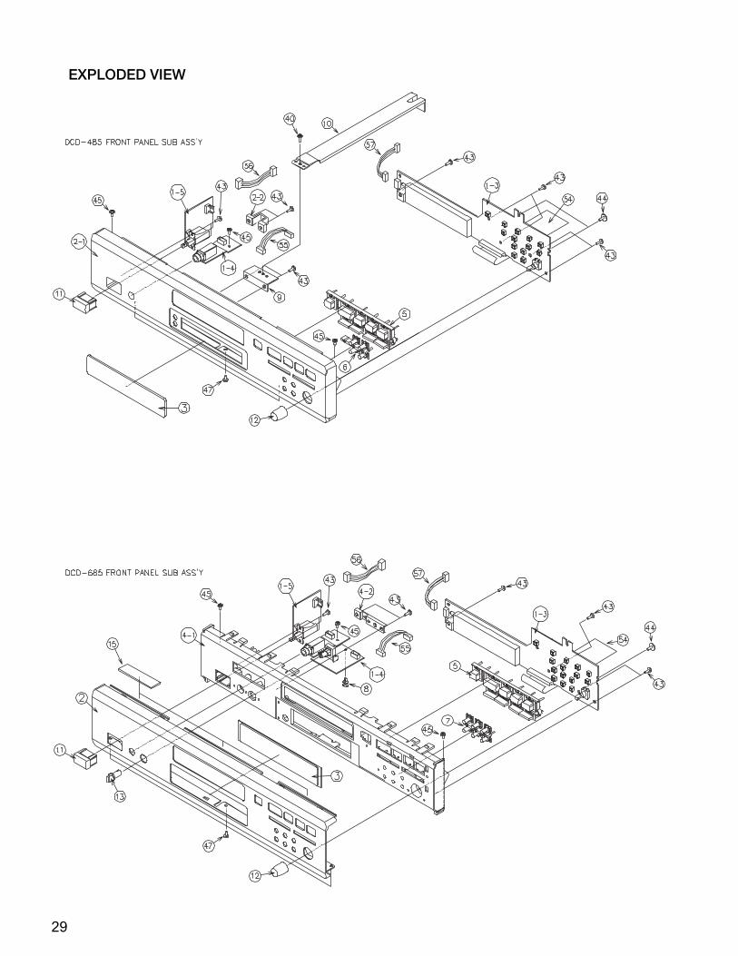
PARTS LIST OF EXPLODED VIEW
Ref.No. Part No. Part Name Remarks Q'ty
1 1U-3346 CD board ass'y DCD-485 model only 11 1U-3346A CD board ass'y DCD-685 model only 11-1 Servo & D/A unit1-2 Power unit1-3 Display unit1-4 H/P jack unit1-5 Power sw unit2-1 146 2232 208 Front panel DCD-485 model only 12-2 - H/P PWB holder DCD-485 model only 12 144 2758 003 Front panel DCD-685 model only 12 144 2758 016 Front panel Gold model only(685) 13 143 1114 001 Window DCD-485 model only 13 143 1066 117 Window DCD-685 model only 14-1 146 2141 409 Inner panel DCD-685 model only 14-1 146 2141 412 Inner panel Gold model only(685) 14-2 - H/P PWB holder DCD-685 model only 15 113 1849 029 Function knob 15 113 1849 074 Function knob Gold model only(685) 16 113 1904 003 Tact knob(4P) DCD-485 model only 17 113 1850 005 Tact knob (6P) Gold model only(685) 17 113 1850 018 Tact knob (6P) DCD-685 model only 18 412 2814 044 Card spacer (L=6) DCD-685 model only 19 412 4782 006 Support bracket(F) DCD-485 model only 110 412 4783 005 Support bracket(B) DCD-485 model only 111 113 9213 000 P•knob (P) ass'y 111 113 9213 084 P•knob (P) ass'y Gold model only(685) 112 112 0851 002 Knob (Maru) 112 112 0851 015 Knob (Maru) Gold model only(685) 113 112 0811 013 Knob (Fuji) DCD-685 model only 113 112 0811 000 Knob (Fuji) Gold model only(685) 115 461 0501 005 Rubber sheet DCD-685 model only 320 411 1386 509 Chassis 121 105 1318 245 Back panel DCD-485 model only 121 105 1318 258 Back panel DCD-685 model only 122 102 0604 003 Top cover 122 102 0604 016 Top cover Gold model only(685) 123 104 0260 100 Foot ass'y 424 412 4784 004 Semko bracket 125 477 0308 009 Hole plug 126 445 0124 008 Flat cable clamp 127 337 0064 003 CD mech(KSL-2130CCM) 128 146 2233 100 Loader panel 128 146 2233 113 Loader panel Gold model only(685) 129 415 9016 035 P.C.B holder 230 412 2814 015 Card spacer (L=14) 131 417 0613 006 Heat sink(PH-0125-M) AS101 132 417 0579 001 Heat sink AS102 133 233 6369 002 Power trans(E2/EK) 150 204 6504 005 14P PH-SAN con cord CX141 151 204 0536 011 6P PH-PH con.cord 152 203 8299 056 5P KR-KR con cord 153 009 0159 013 16P FFC cable 154 009 0133 039 27P FFC 155 203 6514 018 4P PH-PH shield cord 156 203 5132 051 3P VH-VH conn.cord 157 203 8363 034 5P PH-PH conn cord 1 513 2358 007 E2 laser caution 1
513 1642 002 No. sheet 1
Ref.No. Part No. Part Name Remarks Q'ty
SCREWS
40 473 7002 021 3X8 CBTS (S)-B DCD-485 model only 22DCD-685 model only 20
41 477 0064 107 Fixing screw 542 473 7004 016 4X6 CBTS (S)-Z 243 473 7508 017 3X10 CBTS (P)-B DCD-485 model only 11
DCD-685 model only 744 473 8044 017 Special screw DCD-485 model only 2
DCD-685 model only 145 473 8007 025 3X8 cup screw 346 477 0263 005 3P. swelling screw 446 477 0263 018 3P. swelling screw Gold model only 447 473 7002 034 3X6 CBTS (S)-B 3

30
WARNING:Parts marked with this symbol have criticalcharacteristics.Use ONLY replacement parts recommended by themanufacturer.
31
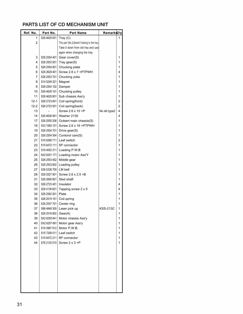
PARTS LIST OF CD MECHANISM UNIT
Ref. No. Part No. Part Name Remarks Q'ty
1 S26 4629 001 Tray (C) 1
2 This part (No.2)doesn't belong to the tray.
Take it down from old tray and use
again when changing the tray.
3 S26 2554 401 Gear cover(S) 1
4 S26 2553 501 Tray gear(S) 1
5 S26 2554 601 Chucking plate 1
6 S26 2629 401 Screw 2.6 x 7 +PTPWH 4
7 S26 2553 701 Chucking yoke 1
8 S14 5249 321 Magnet 1
9 S26 2554 102 Damper 1
10 S26 4629 101 Chucking pulley 1
11 S26 4628 801 Sub chassis Ass'y 1
12-1 S26 2723 601 Coil spring(front) 2
12-2 S26 2723 501 Coil spring(back) 2
13 - Screw 2.6 x 10 +P No slit type2 4
14 S26 4628 901 Washer 2130 4
17 S26 2555 206 Outsert main chassis(S) 1
18 S33 1950 151 Screw 2.6 x 16 +PTPWH 1
19 S26 2554 701 Drive gear(S) 1
20 S26 2554 504 Contorol cam(S) 1
21 S16 9266 711 Leaf switch 2
22 S15 6472 111 5P connector 1
23 S16 4052 311 Loading P.W.B 1
24 SX2 6251 171 Loading motor Ass'Y 1
25 S26 2553 402 Middle gear 1
26 S26 2553 602 Loading pulley 1
27 S36 5338 700 LM belt 1
28 S26 2527 901 Screw 2.6 x 2.5 +B 1
31 S26 2690 801 Sled shaft 1
32 S26 2723 401 Insulator 4
33 S26 4138 601 Tapping screw 2 x 5 4
34 S26 2562 501 Plate 1
35 S26 2519 101 Coil spring 1
36 S26 2547 701 Center ring 1
37 S88 4848 305 Laser pick up KSS-213C 1
38 S26 2518 802 Gear(A) 1
39 SX2 6259 841 Motor chassis Ass'y 1
40 SX2 6257 691 Motor gear Ass'y 1
41 S16 3967 812 Motor P.W.B. 1
42 S15 7208 511 Leaf switch 1
43 S15 6472 211 6P connector 1
44 S76 2125 515 Screw 2 x 3 +P 1

32
EXPLODED VIEW OF CD MECHANISM UNIT KSL 2130 CCM
�
� � � �� � � �
� �
� �
� �
� �
� �
� �
� �
� �
� �
� �
�
�
�
� �
� �
� �
� �
� �
� �
� �
� �
� �
� �
� �
�
� �
� �
�
� �
�
� �
�
� �
�
�
� �
� �
� �
� �
�
� �
� �
�

33
PACKING VIEW
PARTS LIST OF PACKING AND ACCESSORIES
Ref.No. Part No. Part Name Remarks
Q'ty
201 505 0131 050 Cabinet cover 1202 503 1386 002 Cushion 2203 501 2131 001 Carton case DCD-485 model only 1203 501 2131 014 Carton case DCD-685 model only 1204 505 9125 009 Poly cover 1205 515 0867 101 S.S.list(EX) 1206 203 2310 009 2P pin cord 1207 399 0360 006 RC-266 1208 206 2108 003 AC conn with plug Europe model only 1209 511 3758 008 Inst.manual 1210 206 2113 001 AC cord w/con EK U.K. model only 1211 509 9120 006 Spacer carton U.K. model only 1212 - Cont. card 1213 - Bar code label 1214 - Bar code label U.K. model only 1215 513 9111 001 Color label (Gold) Gold model only 2
203
213
212
212
215
214
215
201
202
202
204
205 209
Contents
210211

IC301 PCM1735E
12
34
56
78
910
1112
1314 15
1617
1819
2021
2223
2425
2627
28
OP
EN
CY
041A
1
2
3
4
7
OPENR401
OPENTR401
OPENR404
OPENR405
JK401H/P_8264071
G1
Lch2
Rch3
OPENR406
VR401OPEN
1
42
OPENR402
8
53
OPENTR402
OPENR403
6
560
R14
3
6.8KR103
6.8KR104
6.8KR105
6.8KR10222KR101
22KR106
TR104
IC103LA9241M
12
34
56
78
910
1112
1314
1516
17 18 19 20 21 22 23 24 25 26 27 28 29 30 31 32
3334
3536
3738
3940
4142
4344
4546
4748
49505152535455565758596061626364
33KR210
4.7KR194
10/1
6C
181
680R211
1.5M
R207
C199CK0.047
4.7/
50C
195
10/1
6C
306
CK0.1Z
C307
CK
0.1Z
C30
8
10/1
6C
305
CK0.1ZC303
CK0.1ZC302
CK0.1ZC201
33K
R212
1.2KR213
100/16C203
CK
3300
P
C17
4
0R181
39K
R189
3.3KR190
47/1
6
C17
7
100PC165
30K
R17
6
36K
R178
360
R17
7
330R209
CK0.01C194
22KR202
51KR198
CK
1000
PC
186C184
CK0.1Z
100K
R19
5
10KR200
OP
EN
C18
7
10KR204
33KR201
12PC189
CK1000PC139
47K
R18
3
130KR179
CK
3300
PC
159
27K
R17
4C
K0.
01C
149
2.2K
R17
3
CK0.1ZC144
33K
R16
9
15KR162
6.8K
R16
8
12KR161
CK
0.1ZC
140
CK
0.01
C13
7
47KR166
220P
C145
GND_D1-A
CK0.1ZC104
CK0.1ZC121
39K
R14
8 0R
159
220K
R139
10KR140
OPENC128
OP
EN
R14
915
KR
151
15K
R15
3
8.2K
R15
6
8.2K
R15
8
TR103
560
R13
0
TR102
DTC144EK
TR101
4.7K
R12
1
4.7K
R11
5
1.5K
R15
0
33K
R14
582
KR
144
15K
R13
2
620R133
C12
4C
K0.
047
15K
R12
9C
122
CK
0.04
7
C11
6C
K0.
047
150P
C12
0
C12
5C
K0.
047
CX16116P-FFC
1
2
3
4
5
6
7
8
9
10
11
12
13
14
15
16
CK
1000
PC
142
TR
105
2SA
1037
K(S
/R)
CK0.1Z
C103
47/1
6C
14110
R16
4
GND_D1-A220/16
C147
CK1000PC146
68K
R11
8
0.33
/50
C11
313
KR
119
C11
4
CK
0.01
5
C10
9C
K0.
033
2.2K
R11
633
0PC
110
OP
EN
R20
3GND_D1-A
GND_D1
GND_D1GND_D1-D
R23022
GND_D1-D
100/16C170
CK
0.1Z
C16
7
C15
4C
K0.
047
CK
0.01
C15
7
C14
8C
K0.
33Z
10/1
6
C16
3
CK
0.1Z
C16
6
100/16C168
CK
0.1Z
C16
4
CK
0.1Z
C15
3
100/16C156
GND_D1
100/16C207
CK0.1ZC209
CK0.1ZC219
100/16C221
100/16C304
22R22
922R
228
22R226
47/16C301
CK0.1ZC310GND_D1
47R233
CK0.1ZC222
GND_D1
GND_D1
GND_D1
GND_D1
22R225
100P
C20
4
FB115
EMIFILF
B11
3E
MIF
IL
FB108EMIFIL
FB104EMIFIL
0
R167
3.3/
50 C13
6
CK
0.01 C13
8
GND_D1-A
10KR122
8.2KR235
360P
C22
3
8.2KR234
8.2KR236
8.2KR237
360P
C22
4
R10847
CK
0.1ZC
101
R10
9 47
CK
0.1ZC
102
R11747
CK0.1ZC111
R11047
CK0.1ZC105
R11247
CK0.1ZC106
22KR142
22K
R134
22KR136
22K
R137
22KR141
20K
R12022K
R11
1
22KR138
33K
R135
24KR152
20KR114
2.2/
50
C31
5
5P-KRCX051
1
2
3
4
5
6P-PHCX061
1
2
3
4
5
6
IC101LA6559
12
34
56
78
910
1112
1314
1516
1718 19
2021
2223
2425
2627
2829
3031
3233
3435
36
J700OPENJ701
OPENJ702
OPEN
J703OPEN
C30
947
/16
R30
347
K
R1650
FB
103
EM
IFIL
FB
107
EM
IFIL
FB114EMIFIL
FB112EMIFIL
FB
120
EM
IFIL
FB
119
EM
IFIL
TR
110
OP
EN
TR
111
OP
EN
TR
108
DT
C14
4TK
TR109
DTC144TK
0R
147
C208CK0.1Z
0
R107
0R180
OPENC188
BP
1/50
(BP
)C
173
BP
1/50(BP)C160
C202CK0.1Z
C161OPEN
FB
125
EM
IFIL
IC601uPD78044FGF1883B9
12
34
56
78
910
1112
1314
1516
1718
1920
2122
2324
25 26 27 28 29 30 31 32 33 34 35 36 37 38 39 40
4142
4344
4546
4748
4950
5152
5354
5556
5758
5960
6162
6364
65666768697071727374757677787980
FL601FL TUBE
1 2 3 4 5 6 7 8 9 10 11 12 13 14 15 16 17 18 19 20 21 22 23 24 25 26
5P-PHsCY052
1
2
3
4
5
100KR608100KR607100KR606100KR605100KR604100KR603
100KR633100KR632100KR631100KR630
100K
R61
110
0KR
612
100K
R61
310
0KR
614
100K
R61
510
0KR
616
100K
R62
0
100K
R61
9
100K
R61
8
100K
R62
2
100K
R62
1
100K
R62
3
CK0.1ZC613
SY601OPEN
7
C61
5C
K0.
01
CK
0.01
C61
6C
617
CK
0.1Z
S611ROTARY ENCODER
5 4
R64
810
K
R65
410
K
S611
3
6
R64
710
K
CK
0.01
C61
2
R65
310
K
1
2
CK0.1ZC614CK0.01
C611
4
10K
R64
0
5
GP1UM271XK
IC602
Vcc
1
Vou
t
3
G
2
R637
1K
R638
150
S60
3
S60
2
R649
680
R639
150
R644
270
R641
180
S60
1
R646
390
S60
6
S60
9
S60
8
R642
180
R636
1K
S60
7
R643
270
S61
4
R645
390
S61
0
S60
4
S60
5
S61
7
R651
1.3K
S61
9
R655
3.9K
R652
OPEN
R650
680
R656
OPENCK0.1ZC605
R6240R625OPEN
X601CST4.23MGW040
R6171M
CK0.1ZC603
OPENC604
CK0.1ZC601
27P-FFCCY271
1
2
3
4
5
6
7
8
9
10
11
12
13
14
15
16
17
18
19
20
21
22
23
24
25
26
27
27P-FFCCX271
1
2
3
4
5
6
7
8
9
10
11
12
13
14
15
16
17
18
19
20
21
22
23
24
25
26
27
CK0.1Z
C608
CK
0.1Z
C60
2
J404
SH
OR
T
J403
SH
OR
T
J401
SH
OR
T
J402
SH
OR
T
J406
SH
OR
T
J407
SH
OR
T
C40
3C
K0.
1Z
C40
1C
K0.
01
X103
X-TAL(16.9344MHZ)
12P
C21
4
OPENR221
12PC215
CK0.1ZC225
100P
C60
710
0PC
606
100PC610
OPENC609
1KR
409
TR
403
2SC
3326
4P-PHCY041B
1 2 3 4
1KR
410
56
R40
7
TR
404
2SC
3326
56R
408
CK
0.01
C40
4
CK
0.01
C40
2
47KR154
39KR160
OPENC354
OPENC338
OP
EN
C36
4
680R335
OP
EN
C36
3
OP
EN
C35
1
C38247/16
OP
EN
C33
3
OPENC362
OPENR325
OPENC346
OP
EN
TR
321
OPENIC323
1
2
3
OPENR337
OPENC356
OPENC345
OPENR338
OPENC331
OPENC349
OP
EN
C34
8
30KR329
OPENC336
OP
EN
C36
9
IC321OPEN
1
2
3
4
5
6
7
8 9
10
11
12
13
14
15
16
OPENC353
OPENC350
2SD2144TR323
OPENC377
OPENC358
OPENR323
OPENC332
1K
R340
OP
EN
C33
4
OPENC355
OP
EN
C34
3
2SD2144TR324
OPENR327
C38147/16
C36
0
OPEN
C361
OPENC330
OP
EN
TR
322
OPENC371
1K
R339
30KR330
OPENC357
IC322OPEN
1
2
3
4
5
6
7
8 9
10
11
12
13
14
15
16
SHORTR332
OPENC337
OP
EN
C35
2
C367OPEN
680R336
OPEN
C327
OP
EN
C35
9
OPENIC324
7
6
5
OPENC335 OPENC375
OPENC328
SHORTR331
OP
EN
C34
7
OP
EN
C34
4
OPENC339
OPENC329
OPENC341
OPENC342
OPENC340
OPENIC323
7
5
6 8
4
C373
OPEN
C37
9O
PE
N
OP
EN
C37
8
OP
EN
R32
4
OP
EN
C37
0
OPENIC324
1
3
2 8
4
OPENR328
OPENR326
OPENC372
C36
8O
PE
N
OPENC376
C38
0O
PE
N
OPENC323
BA15218FIC303
7
5
6 4
8
3.6KR309
10KR313
10K
R31
1
2.2/
50C
316
R37130K
R3744.3K
CK0.1ZC391
CK0.1ZC389
GND_A
3.9KR376
+8V_A
3.9K
R37
5
R3734.3K 4P
-PH
CX
041
1
2
3
4
-8V_A
100/
16
C39
0
C388100/16
IC325UPC4570C
1
3
2 C387100/16
IC325UPC4570C
7
5
6 4
8 100/
16C
392
R37230K
R37815K
R37715K
56PC386
56PC385
OPENR321
OPENR322
OPENC366
OPENC365
BA15218FIC303
1
3
2
3.6KR305
CQ
1000
P(N
H)
C31
7
OPENC319
CQ820P(NH)C321
CQ820P(NH)C322
OPENC320
OPENC324
CQ
1000
P(N
H)
C31
8
3.6KR310
3.6KR306
10K
R31
2
10KR314
R30
447
K
OPENIC304
1
2
3
4
5
6
7
8
9
10
11 12
13
14
15
16
17
18
19
20
21
22
OP
EN
C32
6OPENC325
OPENR318
OPENR317
OPENR316
OPEN
R315
R206OPEN
R163OPEN
R22
0O
PE
N
C19
3O
PE
N
R127 OPEN
C17
2O
PE
NC162
OPEN
C21
8O
PE
N
C132OPEN
R187
OPEN
R22
3O
PE
N
C21
0O
PE
N
R157OPEN
R125OPEN
R131OPEN
R124OPEN R
170
OP
EN R222
OPENC133OPEN
OPENIC102
1
2
3
4
5
6
7
8
9 10
11
12
13
14
15
16
17
18
R217OPEN
C206OPEN
R128 OPEN
R182
OPEN
R21
6O
PE
N
X101OPEN
OPEN
ZD102
C171
OPENOPENR218C131
OPEN
R17
1O
PE
N
OP
EN
R21
9
R21
5
OP
EN
R191OPEN
R175OPEN
R17
2
OP
EN
OPENC169
R126 OPEN
IC104
OPEN
1
2
3
4
5
6
7
8 9
10
11
12
13
14
15
16
R22
4O
PE
N
C14
3
OP
EN
C117OPEN
C118OPEN
IC107
1 7
33PC229
JK101TOTX179
GND1
VCC2
Vin3
100/16C228C
K10
00P
C22
6
CK0.1ZC227
CK0.1ZC230
CK0.022ZC220
100R238
BE
AD
SF
B12
7
BEADSFB126
470R232
IC107TC7WU04F
6 28
4
47KR231
CK
0.1Z
C10
7
270KR197
270K
R19
6
6P-NHCX063
1
2
3
4
5
6
CK0.1ZC314
10/16C313
SHORTFB507
OPENJ5026
12
SHORTFB505
D5061SR35-400A
C52
3
CK
6800
P
C5270.01/250
33/5
0C
510
11
R50
210
0(N
B)
TR
504
DTA
144E
K
L501LINE FILTER
12
34
C520CK0.01
OPENC502
100/50C509
TM501EARTH_PLATE
OPENC519
D502
1SR35-400A
C52
2
CK
6800
P
R50710K
OPENC503
D51
01S
S27
0A
D5081SR35-400A
SHORTFB508
C526220/16
CY0222P-VHw
1
2
C51
222
00/2
5
R50
9S
HO
RT
SHORTFB506
ZD501MTZJ6.8A
ZD
502
MT
ZJ2
4A
IC503ICPN20
R51
120
0K
OPENC517
2P_INLETCX021
2
1
5
3
4
BP
C52
8O
PE
N
R5121K(1W)
D505
1SR35-400A
TR503 2SB562(C)T
OPENC514
SHORTFB503
TR5012SD1762(E/F)
8
7
100/
16C
504
D5091SR35-400A
9
D507
1SR35-400A
3.3/50C507
OPEN
J503
R51391(NB)
100/
16C
505
100/
50C
508
OPENC516
T501
2
R50
310
0(N
B)
10
TR505DTC114EK
R50
810
0K
OPENC518
AC PLUG
D5031SR35-400A
1/50C50
6
1/50C53
6
1
1/50C525
SHORTFB502
C52
4
0.01
Z
D504
1SR35-400A
2SB1185(E/F)
TR502
R50
110
K
D501SHORT
R50
410
0K
TR
506
DTA
124X
KA
CX022
2P-VHw
1
2
C51
347
00/2
5
33/5
0C
511
C51
50.
01Z
R51
010
K
OP
EN
C52
1
R50
6
4.7K
S50
1P
OW
ER
-SW
ITC
H(T
V-5
)
TR
507
DT
C11
4EK
JK301
3
4
C38
4C
K10
00P
C38
3C
K10
00P
5
2P-JACK_8537009
JK301
1
2
R60
91K R
610
1K
S61
8
OPEN
S62
0
OPEN
SHORTFB501
OPENC501
SHORTFB504
CX14114P SAN-PH WIRE
1
2
3
4
5
6
7
8
9
10
11
12
13
14
14P-PHCY141
1
2
3
4
5
6
7
8
9
10
11
12
13
14
5P-PHCX052
1
2
3
4
5
10KR602
10KR601
5.1KR629
5.1KR626
10KR627
10KR628
10KR63510K
R634
CK
0.1Z
C13
0
C12
9O
PE
N
C12
7
CK
0.1Z
10/16C312
CK0.1ZC311
GN
D_D
1
OPENR334
OPENR333
C374OPEN
C18
0O
PE
N
C183OPEN
OPENFB102
F.G3C21
1C
K0.
1Z C21
2C
K0.
01 C21
3C
K10
00P
C11
5C
K0.
01C
119
CK
1000
P
IC105OPEN
2 45
3
FB121OPEN
FB123
OPENR205OPEN
FB118OPEN
C185OPEN
C20
0O
PE
N
C20
5O
PE
N
J101
SH
OR
T
R155OPEN
C150OPEN C190
OPEN
C19
2O
PE
N
OPENC191
FB105OPEN
FB116OPEN
C1510
FB106OPEN
C1750
FB111OPEN
C1760
C1520
C158CK0.1Z
C155CK0.01
F.G3
F.G3
OPENX102
C18
2
OP
EN
C17
8
C17
9
R192OPEN
R193OPEN
R214OPEN
C197OPEN
C19
8O
PE
N
C196OPEN
0FB101R146
0
0FB109
R1850
OPENFB117R199
OPEN
R18
8O
PE
N
FB110OPEN
C21
7O
PE
N
C21
6O
PE
NF
B12
2O
PE
N
FB
124
SH
OR
T
IC1073 5
R37991(NB)
R38091(NB)
+8V_A
-8V_A
+8V_A
2SD1762(E/F)TR106
MT
ZJ6
.8A
ZD
101
120(1W)R123
100K
R11
3
220/25C532
CK0.01
C123
100/
16C
108
CK
0.1Z
C11
2
GND_D3
GND_D3
GND_D2
+5V_D2
+5V_D2
GND_D2
+5V_D1
GND_D1
-5V_D1
-5V_D1
GND_D1
-5V_A
+5V_A
-5V_A
+5V_A
-5V_A
+5V_A
R5054.7K
+5V_D1
+5V_D1
+5V_D1
+5V_D1
+5V_D1
+5V_D1
+5V_D1
GND_D1
IC11
0O
PE
N
2 45
3
CX024
OPEN
1
2
GND_D1
+5V_D1
C13
4O
PE
N
C135OPEN
OP
EN
LD10
1IC111OPEN
D2
CK1
CLR
6
Q3
Q5
PR
7
GND
4
VCC
8
+5V_D1
0R
184
100PC618
GND_D1
+5V_D1
+5V_A
GND_A
GND_D1
+5V_D1CK0.1ZC231
CK0.01C232
C233OPEN
100PC234
100PC238
OPENC393
100R227
100PC236
100PC239
100PC237OPENC235
OPENR208
OPENC243
OP
EN
C24
4
OP
EN
C24
5
OPENC242
OPENR239
JK102OPEN
1
2
3
67
T101OPEN
3
2
1 5
4
OPENC241
OPENC240
IC108
OPEN1 7
IC108OPEN
3 5
IC108OPEN
6 28
4
47KR240
OPENR241
OPENC248
OP
EN
C24
6
OPENC247
OPENR242
100/16C249
IC50
2M
5290
P
123456789 10 11 12 13 14 15 16
CK0.1ZC394
J102SHORT
100PC395
100PC396
OPENR243
VR101OPEN
OPENR244
OPENR245
GND_D1-A
+5V_D1-A
+5V_D1-A
OPENR249
R24710K
R24810K
R24610K
+5V_D1
R4110
0R
250
100/
16C25
5
CK
0.01
C25
4
GND_D1-A
100/
16C
252
CK
0.01C25
3
ST1
STYLE-PIN
ST2
STYLE-PIN
CK
0.01
C40
5
CK
0.01
C40
6
CK
0.1Z
C40
7
CK
0.01
C40
8
CK
0.1Z
C40
9
GND_D1
F.G3 F.G5 F.G4
GND_D1
OP
EN
C25
0
OP
EN
C25
1
AS1FL SPACER(T=5)
1 AS2FL SPACER(T=5)
1
CX0535P-NH
1
2
3
4
5
OPENR251
W702
OPEN
220/16C256
10KR252
W701A1P WIRE
W7011P WIRE
W702AOPEN
0R
657
47K
R30
7
47KR308
CK0.1ZC257
CK
0.1Z
C39
7
CK
0.01
C39
8
HEAT SINKAS101
220PC258
C531
CK0.1Z
HEAT SINKAS1021
CK
0.1Z
C52
9C
K0.
1ZC
530
C41
2C
K0.
01
C413CK0.1Z
C41
0C
K0.
01
C41
1C
K0.
1Z
CK
0.1Z
C53
3
CK
0.1Z
C53
4
R90
3O
PE
N
R901OPEN
R902OPEN
R900OPEN
C25
9O
PE
N
ST501
STYLE-PIN1
ST502
STYLE-PIN1
0R
186
C535OPEN
OPENSY6011
IC106
LC78625E
12
34
56
78
910
1112
1314
1516
1718
1920
2122
2324
25 26 27 28 29 30 31 32 33 34 35 36 37 38 39 40
4142
4344
4546
4748
4950
5152
5354
5556
5758
5960
6162
6364
65666768697071727374757677787980
FO+
TR-
DSP_RST.
TR+
FO+
FO-
CLOSE.
FO-
SL+
LOOD-
SL-
LOOD-
LOOD+
SP+
SP-
SL+
SL-
SP+SP-
TR-
TR+
LOOD+
G2
G3
G4
G5
G6
P16
P15
P14
P13
P12
P11
P10 P
9
P8
P7
P6
P5
P4
P3
P2
P1
G1
G2
G3
G4
G5
G6
P16
P15
P14
P13
P12
P11
P10
P9
P8
P7
P6
P5
P4
P3
P2
P1
G1
JOG_B
JOG_A
INSW
CLSW
OPSW
FSEQ
SL-
..
SL+
..
RW
C
MC
E
MC
S
RESET
COIN
CQCK
MDATA
MCLK
MCLK
MDATA
ML
COIN
SQOUT
RESET
DSP_RST
DA_RST
RWC
SL+..
SL-..
CD/RW
SERCH
WRQ
DRF
FSEQ
A_MUTE
DRV_MUTE
OPSW
CLSW
INSW
OPEN
CLOSE
MLCQCK
DSP_RST.
DA_RST.
DRV_MUTE.
DRF.
WRQ.
SERCH.
OPSW.
CLSW.
INSW.
OPEN.
CLOSE.
SQ
OU
T.
WR
Q.
MDATA.
ML.
MCLK.
DA_RST.
MCS.
AD
1
DRF
WRQ
SE
RC
H.
SL+
.
SL-
.
FSEQ.
CLS
W.
OP
SW
.
A_MUTE.
ML.
MCLK.
MDATA.
LRCK
DATA
BCK
DATA
BCK
LRCK
MCK
MCE.
DRV_MUTE.
SERCH.
CD/RW.
DR
F.
AD
0
F1
F2
DA_RST
DSP_RST
DRV_MUTE
A_MUTE
OPEN
CLOSE
OPEN.
DR
F.
MCLK.
MDATA.
MCS.
MCE
MCS
CD/RW
SERCH
CO
IN.
DA_RST.
MCK
RW
C.
CQ
CK
. AD0
AD1
JOG_A
JOG_B
INSW.
CLSW.
OPSW.
SQOUT
CQCK.
COIN.
SQOUT.
RWC.
CD/RW.
MDATA.
MCLK.
ML.
MCE.
SL+.
SL-.
GND_A
H/P VR UNIT1U-3346-4
LRCK
DATA
BCK
CLKO
XTI
XTO
DGND
VDD
VCC2R
AGND2R
EXTR
NC
VOUTR
AGND1
ML/IIS
MC/DM1
MD/DM0
MUTE
MODE
CS/WO
RST
ZEROL
VCC2L
AGND2L
EXTL
ZEROR
VOUTL
VCC1
LD
C
E
B
A
F
GND
MD
DFIN2
FIN1
E
F
TB
TE-
TE
TESI
SCI
TH
TA
TD-
TD
JP
TO
FD
FD
-
FA FA-
FE
FE
-
AG
ND
NC
SP
SP
G
SP
-
SP
D
SLE
Q
SLD
SL-
SL+
JP-
TES
CV-
DGND
SLOF
RFS-
NC
TGL
RFSM
TBC
SLI
JP+
CV+
FSC
HFL
SLC
TOFF
VCC1
LDS
LDD
BH
1
PH
1
LF2 VR
RE
FI
VC
C2
FS
S
DR
F CE
DAT C
L
CLK
DE
F
DEFI
TAI
PDO
VVSS
ISET
VVDD
FR
VSS
EFMO
EFMO
EFMIN
TEST2
CLV+
CLV-
FOCS
FST
FZD
HFL
TES
PCK
FSEQ
TOFF
TGL
TH
LD
TE
ST
3
VD
D
JP+
JP-
DE
MO
TE
ST
4
EM
PH
LRC
KO
DF
OR
O
DF
OLO
DA
CK
O
TS
T10
P0
P1
P2
RWC
WRQ
FSX
SBCK
SFSY
PW
EFLG
SBSY
DOUT
SQ
OU
T
CO
IN
CQ
CK
RE
S
TS
T11
LAS
ER
16M
4.2MCO
NT
TE
ST
5
CS
XV
SS
XIN
XO
UT
XV
DD
TE
ST
1
MUTER
RVDD
RCHP
RCHN
RVSS
LVSS
LCHN
LCHP
LVDD
MUTEL
C2F
ROMXA
CK2
P3
LRSY
VR
To C
D M
echa
VC
VCC
To C
D M
echa
To C
D M
echa
GND
DEF
CLK
CL
DAT
CE
x4
RESET
P33
P120
SI1
SO1
1U-3346-1
MAIN UNIT
1U-3346-5H/P JACK UNITA
NI3
AN
I2
AN
I1
AN
I0
AV
DD
AV
RE
F
P04
XT
2
VS
S
X1
X2
P37
P36
P35
P34
P32
P31
P30
INTP3
INTP2
INTP1
P00
IC
P72
P71
P70
VDD
P127
P126
P125
P124
P123
P122
P121
FIP25
FIP24
FIP23
FIP22
FIP
21
FIP
20
FIP
19
FIP
18
FIP
17
FIP
16
VLO
AD
FIP
15
FIP
14
FIP
13
P97
P96
FIP
12
FIP
11
FIP
10
P95
P94
FIP5
FIP4
FIP3
FIP2
FIP1
FIP0
VDD
SCK0
SO0
SI0
P24
P23
SCK1
P74
P73
AVSS
P17
P16
P15
P14
ENTER
STO
P
PLA
Y
OP
/CL
TIM
E
A.E
DIT
PAU
SE
ALL
DIS
P
RA
ND
OM
A.S
PAC
E
A-B
P.SW UNIT
1U-3346-7
1U-3346-3
DISP. UNIT
POWER UNIT
1U-3346-2
H/P JACK UNIT
1U-3346-6
DRF
IOUT
SERVO DC
BPO DC
+Vcc
-Vcc
WCLK
DATA
DGND
REF DC
NC BPO DC
2/2
BCLK
1/2
REF DC
1/2
-Vdd
+Vdd
IOUT
AGND
SERVO DC
+Vcc
WCLK
-Vcc
NC
+Vdd
DGND
AGND
AGND
NC
-Vdd
BCLK
DATA
AGND
NC
2/2
(1/2)
(2/2)
(1/2)
L
(2/2)
MUTE
GND
R
XIN
XI
S2
VSSA
VSSXO
VDD
LOCK
S1
M2
M1
CKO
VDDA
PD
D0
PD2
P3
P1
AMIN
IFIN
P2
P0
[1/1]
XOUT
AMPO
AMPI
REF
[VCO PIT]
VSS
PD1
VDD
FMINCK
CE
SD
DA
DIGITAL OUT
[2/3]
[1/3]
VC
FEO
DRF
NC
TEO
NC
+8V[A1-1]
EO
-
-5V[D1]
CO
-
NC
NC
EO
+
+8V[A1-1]
BA
L
-5VD
-VC
C
GN
D
GND[D1-1]
-8V[A1-1]
-5V[D1-1]
GND[D3-1]
RE
SE
T
+5V[D1-1]
VC
C
CO
+
5VON
/OF
F
+5V[A1]
RE
F
FG
Rch
Lch
[-]
[+]
+5V[D2]
GND[D2]
+5V[D1]
+5V[D1-2]
GND[D1]
GND[D1-2]
-5V[A1-1]
GND[A1]
LINE_MUTE
A_MUTE
RESET
-5V[D1]
GND[A1]
GND[D3-1]
LINE_MUTE
GND[D2]
GND[D1]
+5V[A1]
RESET
-8V[A1-1]
+5V[D2]
-5V[A1-1]
+8V[A1-1]
A_MUTE
+5V[D1]
-HB
F1
F2
-HB
GND[D1-2]
F2
+5V[D1-2]
F1
BCKI
LRCI
NC
BKO
DIN
NC
DG
DOL
WCKO
DOR
VDDNC
NC
CKSL
MCK
CKO
RST
MLEN
XTO
VSS
XTI
MDT
VO3+
S-VCC
VLO+
VCC2
FR
VO2+
VLO-
VO3-
REV
VO4+
VO4-
VIN2
VO1+
VIN1
VO1-
VCC1
VO2-
VIN1-
VIN1+
VCC-VREG
VIN2+
VIN4+
VIN4-
FWD
REG-IN
VCONT
MUTE1
REG-OUT
FR
MUTE2
VIN4
S-GND
VIN3
VREF-IN
VIN3-
GND-VREG
VIN3+
VIN2-
GND
CLOSE
OPEN
HF
+5V
[ASP]
[DSP]
[CPU]
[DRIVER]
[DF]
[3/3]
[2/3]
[1/3]
[3/3]
DIGITAL OUT
[COAXAL]
[OPTICAL]
[Focus Bias]
POWER TRANS
V/P
OP
EN
OP
EN
OP
EN
NOTICEALL RESISTANCE VALUES IN OHM. k=1,000 OHM M=1,000,000 OHMALL CAPACITANCE VALUES IN MICRO FARAD. P=MICRO-MICRO FARADEACH VOLTAGE AND CURRENT ARE MEASUERD AT NO SIGNAL INPUTCONDITION.CIRCUIT AND PARTS ARE SUBJECT TO CHANGE WITHOUT PRIORNOTICE.
WARNING:Parts marked with this symbol have critical characteristics.Use ONLY replacement parts recommended by the manufacture.
CAUTION:Before returning the unit to the customer, make sure you make either (1) aleakage current check or (2) a line to chassis resistance check. If the leakagecurrent exceeds 0.5 milliamps, or if the resistance from chassis to either sideof the power card is less than 460 kohms, the unit is defective.
WARNING:DO NOT return the unit to the customer until the problem is located andcorrected.
+B LINE- B LINE
SIGNAL LINE
SCHEMATIC DIAGRAM ( for DCD-485 )
SCHEMATIC DIAGRAM ( for DCD-485 )1U-3346
34
A
C
B
D

12 27
28
560
R14
3
6.8KR103
6.8KR104
6.8KR105
6.8KR10222KR101
22KR106
TR104
IC103LA9241M
12
34
56
78
910
1112
1314
1516
17 18 19 20 21 22 23 24 25 26 27 28 29 30 31 32
3334
3536
3738
3940
4142
4344
4546
4748
49505152535455565758596061626364
33KR210
4.7KR194
10/1
6C
181
680R211
1.5M
R207
C199CK0.047
4.7/
50C
195
CK0.1ZC201
33K
R212
1.2KR213
100/16C203
CK
3300
P
C17
4
100PC165
K76
330R209
CK0.01C194
22KR202
51KR198
CK
1000
PC
186C184
CK0.1Z
100K
R19
5
10KR200
OP
EN
C18
7
10KR204
33KR201
12PC189
CK1000PC139
47K
R18
3
130KR179
CK
3300
PC
159
27K
R17
4C
K0.
01C
149
33K
R16
9
15KR162
6.8K
R16
8
12KR161
CK
0.1ZC
140
K0.
01C
137
47KR166
GND_D1-A
CK0.1ZC104
CK0.1ZC121
220K
R139
10KR140
OPENC128
OP
EN
R14
915
KR
151
15K
R15
3
8.2K
R15
6
8.2K
R15
8
TR103
560
R13
0
TR102
DTC144EK
TR101
4.7K
R12
1
4.7K
R11
5
1.5K
R15
0
33K
R14
582
KR
144
15K
R13
2
620R133
C12
4C
K0.
047
15K
R12
9C
122
CK
0.04
7
C11
6C
K0.
047
150P
C12
0
C12
5C
K0.
047
CX16116P-FFC
1
2
3
4
5
6
7
8
9
10
11
12
13
14
15
16
CK
1000
PC
142
TR
105
2SA
1037
K(S
/R)
CK0.1Z
C103
47/1
6C
14110
R16
4
GND_D1-A220/16
C147
CK1000PC146
68K
R11
8
0.33
/50
C11
313
KR
119
C11
4
CK
0.01
5
C10
9C
K0.
033
2.2K
R11
633
0PC
110
OP
EN
R20
3
GND_D1-A
GND_D1
GND_D1GND_D1-D
R23022
GND_D1-D
100/16C170
CK
0.1Z
C16
7
C15
4C
K0.
047
CK
0.01
C15
7
C14
8C
K0.
33Z
10/1
6
C16
3
CK
0.1Z
C16
6
100/16C168
CK
0.1Z
C16
4
CK
0.1Z
C15
3
100/16C156
GND_D1
100/16C207
CK0.1ZC209
CK0.1ZC219
100/16C221
22R22
922R
228
22R226
47R233
CK0.1ZC222
GND_D1
GND_D1
GND_D1
22R225
100P
C20
4
FB115
EMIFIL
FB
113
EM
IFIL
FB108EMIFIL
FB104EMIFIL
0
R167
3.3/
50 C13
6
CK
0.01 C13
8
GND_D1-A
10KR122
8.2KR235
360P
C22
3
8.2KR234
8.2KR236
8.2KR237
360P
C22
4
R10847
CK
0.1ZC
101
R10
9 47
CK
0.1ZC
102
R1650
FB
103
EM
IFIL
FB
107
EM
IFIL
FB114EMIFIL
FB112EMIFIL
FB
120
EM
IFIL
FB
119
EM
IFIL
TR
110
OP
EN
TR
111
OP
EN
TR
108
DT
C14
4TK
0R
147
C208CK0.1Z
0
R107
OPENC188
C202CK0.1Z
FB
125
EM
IFIL
X103
X-TAL(16.9344MHZ)
12P
C21
4
OPENR221
12PC215
CK0.1ZC225
R206OPEN
R163OPEN
R22
0O
PE
N
C19
3O
PE
N
R127 OPEN
C17
2O
PE
NC162
OPEN
C21
8O
PE
N
C132OPEN
R187
OPEN
R22
3O
PE
N
C21
0O
PE
N
R157OPEN
R125OPEN
R131OPEN
R124OPEN R
170
OP
EN R222
OPENC133OPEN
OPENIC102
1
2
3
4
5
6
7
8
9 10
11
12
13
14
15
16
17
18
R217OPEN
C206OPEN
R128 OPEN
R182
OPEN
R21
6O
PE
N
X101OPEN
OPEN
ZD102
C171
OPENOPENR218C131
OPEN
R17
1O
PE
N
OP
EN
R21
9
R21
5
OP
EN
R191OPEN
R175OPEN
R17
2
OP
EN
OPENC169
R126 OPEN
IC104
OPEN
1
2
3
4
5
6
7
8 9
10
11
12
13
14
15
16
R22
4O
PE
N
C14
3
OP
EN
C117OPEN
C118OPEN
IC107
1 7
33PC229
100/16C228C
K10
00P
C22
6
CK0.1ZC227
CK0.1ZC230
CK0.022ZC220
100R238
BE
AD
SF
B12
7
BEADSFB126
470R232
IC107TC7WU04F
6 28
4
47KR231
10/16C312
CK
C18
0O
PE
N
C183OPEN
OPENFB102
F.G3C21
1C
K0.
1Z C21
2C
K0.
01 C21
3C
K10
00P
C11
5C
K0.
01C
119
CK
1000
P
IC105OPEN
2 45
3
FB121OPEN
FB123
OPENR205OPEN
FB118OPEN
C185OPEN
C20
0O
PE
N
C20
5O
PE
N
J101
SH
OR
T
R155OPEN
C150OPEN C190
OPEN
C19
2O
PE
N
OPENC191
FB105OPEN
FB116OPEN
C1510
FB106OPEN
C1750
FB111OPEN
C1760
C1520
C158CK0.1Z
C155CK0.01
F.G3
F.G3
OPENX102
C18
2
OP
EN
C17
8
C17
9
R192OPEN
R193OPEN
R214OPEN
C197OPEN
C19
8O
PE
N
C196OPEN
0FB101R146
0
0FB109
R1850
OPENFB117R199
OPEN
R18
8O
PE
N
FB110OPEN
C21
7O
PE
N
C21
6O
PE
NF
B12
2O
PE
N
FB
124
SH
OR
T
IC1073 5
+8V_A
+5V_D2
GND_D2
+5V_D1
+5V_D1
+5V_D1
+5V_D1
+5V_D1
+5V_D1
GND_D1
IC11
0O
PE
N
2 45
3
GND_D1
+
C13
4O
PE
N
C135OPEN
IC111OPEN
D2
CK1
CLR
6
Q3
Q5
PR
7
GND
4
VCC
8
0R
184
C233OPEN
100PC234
100PC238
100R227
100PC236
100PC239
100PC237OPENC235
OPENR208
OC
67
T101OPEN
3
2
1
OPENC241
OPENC240
IC108
OPEN1 7
IC108OPEN
3 5
IC108OPEN
6 28
4
47KR240
OPENR241
OPENC248
OP
EN
C24
6
OPENC247
OPENR242
J102SHORT
+5V_D1-A
OPENR249
0R
250
100/
16C25
5
CK
0.01
C25
4
GND_D1-A
100/
16C
252
CK
0.01C25
3
GND_D1
OP
EN
C25
0
OP
EN
C25
1
OPENR251
W702
OPEN
CK0.1ZC257
HEAT SINKAS101
220PC258
C25
9O
PE
N
0R
186
IC106
LC78625E
12
34
56
78
910
1112
1314
1516
1718
1920
2122
2324
25 26 27 28 29 30 31 32 33 34 35 36 37 38 39 40
4142
4344
4546
4748
4950
5152
5354
5556
5758
5960
6162
6364
65666768697071727374757677787980
FO+
DSP_RST.
FO-TR-
TR+
SQ
OU
T.
WR
Q.
ML.
MCLK.
LRCK
DATA
MCE.
CD/RW. MCLK.
MDATA.
CO
IN.
RW
C.
CQ
CK
.
LRCK
DATA
ML/IIS
LD
C
E
B
A
F
GND
MD
DFIN2
FIN1
E
F
TB
TE-
TE
TESI
SCI
TH
TA
TD-
TD
JP
TO
FD
FD
-
FA FA-
FE
FE
-
AG
ND
NC
SP
SP
G
SP
-
SP
D
SLE
Q
SLD
SL-
SL+
JP-
TES
CV-
DGND
SLOF
RFS-
NC
TGL
RFSM
TBC
SLI
JP+
CV+
FSC
HFL
SLC
TOFF
VCC1
LDS
LDD
BH
1
PH
1
LF2 VR
RE
FI
VC
C2
FS
S
DR
F CE
DAT C
L
CLK
DE
F
DEFI
TAI
PDO
VVSS
ISET
VVDD
FR
VSS
EFMO
EFMO
EFMIN
TEST2
CLV+
CLV-
FOCS
FST
FZD
HFL
TES
PCK
FSEQ
TOFF
TGL
TH
LD
TE
ST
3
VD
D
JP+
JP-
DE
MO
TE
ST
4
EM
PH
LRC
KO
DF
OR
O
DF
OLO
DA
CK
O
TS
T10
P0
P1
P2
RWC
WRQ
FSX
SBCK
SFSY
PW
EFLG
SBSY
DOUT
SQ
OU
T
CO
IN
CQ
CK
RE
S
TS
T11
LAS
ER
16M
4.2MCO
NT
TE
ST
5
CS
XV
SS
XIN
XO
UT
XV
DD
TE
ST
1
MUTER
RVDD
RCHP
RCHN
RVSS
LVSS
LCHN
LCHP
LVDD
MUTEL
C2F
ROMXA
CK2
P3
LRSY
VR
To C
D M
echa
VC
VCC
DEF
CLK
CL
DAT
CE
x4DRF
XIN
XI
S2
VSSA
VSSXO
VDD
LOCK
S1
M2
M1
CKO
VDDA
PD
D0
PD2
P3
P1
AMIN
IFIN
P2
P0
[1/1]
XOUT
AMPO
AMPI
REF
[VCO PIT]
VSS
PD1
VDD
FMINCK
CE
SD
DA
[2/3]
[1/3]
[ASP]
[DSP]
[3/3]
[2/3]
[1/3]
[3/3]
V/P
OP
EN
OP
EN
SCHEMATIC DIAGRAM ( for DCD-485 )

OP
EN
CY
041A
1
2
3
4
7
OPENR401
OPENTR401
OPENR404
OPENR405
JK401H/P_8264071
G1
Lch2
Rch3
OPENR406
VR401OPEN
1
42
OPENR402
8
53
OPENTR402
OPENR403
6
8.2KR235
8.2KR234
8.2KR236
8.2KR237
J700OPENJ701
OPENJ702
OPEN
J703OPEN
EM
IFIL
IC601uPD78044FGF1883B9
12
34
56
78
910
1112
1314
1516
1718
1920
2122
2324
25 26 27 28 29 30 31 32 33 34 35 36 37 38 39 40
4142
4344
4546
4748
4950
5152
5354
5556
5758
5960
6162
6364
65666768697071727374757677787980
FL601FL TUBE
1 2 3 4 5 6 7 8 9 10 11 12 13 14 15 16 17 18 19 20 21 22 23 24 25 26
5P-PHsCY052
1
2
3
4
5
100KR608100KR607100KR606100KR605100KR604100KR603
100KR633100KR632100KR631100KR630
100K
R61
110
0KR
612
100K
R61
310
0KR
614
100K
R61
510
0KR
616
100K
R62
0
100K
R61
9
100K
R61
8
100K
R62
2
100K
R62
1
100K
R62
3
CK0.1ZC613
SY601OPEN
7
C61
5C
K0.
01
CK
0.01
C61
6C
617
CK
0.1Z
S611ROTARY ENCODER
5 4
R64
810
K
R65
410
K
S611
3
6
R64
710
K
CK
0.01
C61
2
R65
310
K
1
2
CK0.1ZC614CK0.01
C611
4
10K
R64
0
5
GP1UM271XK
IC602
Vcc
1
Vou
t
3
G
2
R637
1K
R638
150
S60
3
S60
2
R649
680
R639
150
R644
270
R641
180
S60
1
R646
390
S60
6
S60
9
S60
8
R642
180
R636
1K
S60
7
R643
270
S61
4
R645
390
S61
0
S60
4
S60
5
S61
7
R651
1.3K
S61
9
R655
3.9K
R652
OPEN
R650
680
R656
OPENCK0.1ZC605
R6240R625OPEN
X601CST4.23MGW040
R6171M
CK0.1ZC603
OPENC604
CK0.1ZC601
27P-FFCCY271
1
2
3
4
5
6
7
8
9
10
11
12
13
14
15
16
17
18
19
20
21
22
23
24
25
26
27
27P-FFCCX271
1
2
3
4
5
6
7
8
9
10
11
12
13
14
15
16
17
18
19
20
21
22
23
24
25
26
27
CK0.1Z
C608
CK
0.1Z
C60
2
J404
SH
OR
T
J403
SH
OR
T
J401
SH
OR
T
J402
SH
OR
T
J406
SH
OR
T
J407
SH
OR
T
C40
3C
K0.
1Z
C40
1C
K0.
01
100P
C60
710
0PC
606
100PC610
OPENC609
1KR
409
TR
403
2SC
3326
4P-PHCY041B
1 2 3 4
1KR
410
56
R40
7
TR
404
2SC
3326
56R
408
CK
0.01
C40
4
CK
0.01
C40
2
IC303
GND_A
C321
33PC229
JK101TOTX179
GND1
VCC2
Vin3
100/16C228C
K10
00P
C22
6
CK0.1ZC227
CK0.1ZC230
100R238
BE
AD
SF
B12
7
BEADSFB126
2
R60
91K R
610
1K
S61
8
OPEN
S62
0
OPEN
CX14114P SAN-PH WIRE
1
2
3
4
5
6
7
8
9
10
11
12
13
14
10KR602
10KR601
5.1KR629
5.1KR626
10KR627
10KR628
10KR63510K
R634
10/16C312
CK0.1ZC311
IC1073 5
+8V_A
-8V_A
GND_D2
+5V_D2
+5V_D1
GND_D1
-5V_D1
-5V_A
+5V_A
+5V_A
+5V_D1
GND_D1
IC11
0O
PE
N
2 45
3
CX024
OPEN
1
2
GND_D1
+5V_D1
C13
4O
PE
N
C135OPEN
OP
EN
LD10
1IC111OPEN
D2
CK1
CLR
6
Q3
Q5
PR
7
GND
4
VCC
8
100PC618
GND_D1
OPENC243
OP
EN
C24
4
OP
EN
C24
5
OPENC242
OPENR239
JK102OPEN
1
2
3
67
T101OPEN
3
2
1 5
4
OPENC241
OPENC240
IC108OPEN
IC108OPEN
6 28
4
0
PEN248
OPENR242
100/16C249
OPENR249
R4110
AS1FL SPACER(T=5)
1 AS2FL SPACER(T=5)
1
W7011P WIRE
W702AOPEN
0R
657
C41
2C
K0.
01
C413CK0.1Z
C41
0C
K0.
01
C41
1C
K0.
1Z
OPENSY6011
G2
G3
G4
G5
G6
P16
P15
P14
P13
P12
P11
P10 P
9
P8
P7
P6
P5
P4
P3
P2
P1
G1
G2
G3
G4
G5
G6
P16
P15
P14
P13
P12
P11
P10
P9
P8
P7
P6
P5
P4
P3
P2
P1
G1
JOG_B
JOG_A
INSW
CLSW
OPSW
FSEQ
SL-
..
SL+
..
RW
C
MC
E
MC
S
RESET
COIN
CQCK
MDATA
MCLK
MCLK
MDATA
ML
COIN
SQOUT
RESET
DSP_RST
DA_RST
RWC
SL+..
SL-..
CD/RW
SERCH
WRQ
DRF
FSEQ
A_MUTE
DRV_MUTE
OPSW
CLSW
INSW
OPEN
CLOSE
MLCQCK
DSP_RST.
DA_RST.
DRV_MUTE.
DRF.
WRQ.
SERCH.
OPSW.
CLSW.
INSW.
OPEN.
CLOSE.
ML.
MCLK.
AD
1
DRF
WRQ
FSEQ.
A_MUTE.
AD
0
DA_RST
DSP_RST
DRV_MUTE
A_MUTE
OPEN
CLOSE
MCS.
MCE
MCS
CD/RW
SERCH
AD0
AD1
JOG_A
JOG_B
SQOUT
CQCK.
COIN.
SQOUT.
RWC.
CD/RW.
MDATA.
MCLK.
ML.
MCE.
SL+.
SL-.
GND_A
H/P VR UNIT1U-3346-4
RESET
P33
P120
SI1
SO1
1U-3346-5H/P JACK UNITA
NI3
AN
I2
AN
I1
AN
I0
AV
DD
AV
RE
F
P04
XT
2
VS
S
X1
X2
P37
P36
P35
P34
P32
P31
P30
INTP3
INTP2
INTP1
P00
IC
P72
P71
P70
VDD
P127
P126
P125
P124
P123
P122
P121
FIP25
FIP24
FIP23
FIP22
FIP
21
FIP
20
FIP
19
FIP
18
FIP
17
FIP
16
VLO
AD
FIP
15
FIP
14
FIP
13
P97
P96
FIP
12
FIP
11
FIP
10
P95
P94
FIP5
FIP4
FIP3
FIP2
FIP1
FIP0
VDD
SCK0
SO0
SI0
P24
P23
SCK1
P74
P73
AVSS
P17
P16
P15
P14
ENTER
STO
P
PLA
Y
OP
/CL
TIM
E
A.E
DIT
PAU
SE
ALL
DIS
P
RA
ND
OM
A.S
PAC
E
A-B
1U-3346-3
DISP. UNIT
H/P JACK UNIT
1U-3346-6
DIGITAL OUT
[-]
[+]
-5V[D1]
GND[A1]
GND[D3-1]
LINE_MUTE
GND[D2]
GND[D1]
+5V[A1]
RESET
-8V[A1-1]
+5V[D2]
-5V[A1-1]
+8V[A1-1]
A_MUTE
+5V[D1]
-HB
GND[D1-2]
F2
+5V[D1-2]
F1
[CPU]
[3/3]
[2/3]
[3/3]
DIGITAL OUT
[COAXAL]
[OPTICAL]
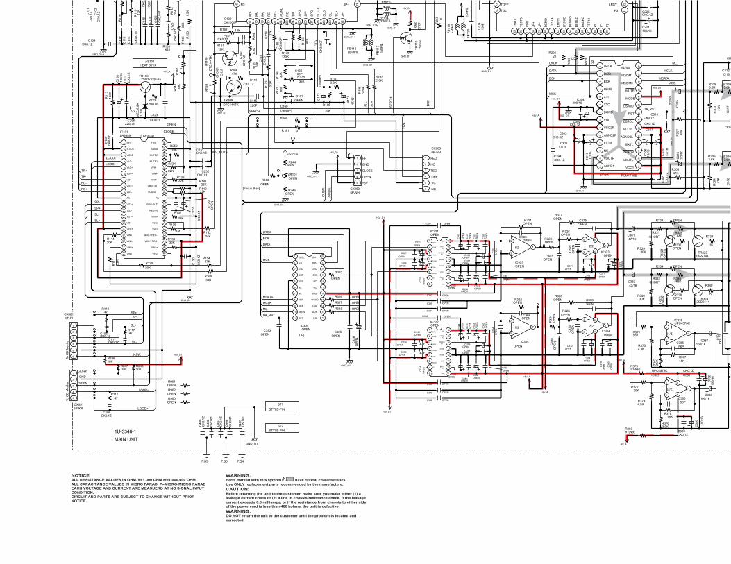
IC301 PCM1735E
12
34
56
78
910
1112
1314 15
1617
1819
2021
2223
2425
2627
28
16
17 18 19 20 21 22 23 24 25 26 27 28 29 30 31 32
33
10/1
6C
306
CK0.1Z
C307
CK
0.1Z
C30
8
10/1
6C
305
CK0.1ZC303
CK0.1ZC302
CK
3300
P
C17
4
0R181
39K
R189
3.3KR190
47/1
6
C17
7
100PC165
30K
R17
6
36K
R178
360
R17
7
CK1000PC139
47K
R18
3
130KR179
CK
3300
PC
159
27K
R17
4C
K0.
01C
149
2.2K
R17
3
CK0.1ZC144
33K
R16
9
15KR162
6.8K
R16
8
12KR161
CK
0.1ZC
140
CK
0.01
C13
7
47KR166
220P
C145
GND_D1-A
CK0.1ZC104
39K
R14
8 0R
159
1.5K
R15
0
33K
R14
5
15K
R13
2
620R133
C12
2C
K0.
047
C11
6C
K0.
150P
C12
0
C12
5C
K0.
047
13K
R11
9
C11
4
CK
0.01
5
R11
633
0PC
110
OP
EN
R20
3
GND_D1-A
GND_D1
GND_D1GND_D1-D
GND_D1
100/16C221
100/16C304
22R22
922R
228
22R226
47/16C301
CK0.1ZC310GND_D1
GND_D1
GND_D1
100P
C20
4
EMIFIL
FB
113
EM
IFIL
CK
0.1ZC
101
CK
0.1ZC
102
R11747
CK0.1ZC111
R11047
CK0.1ZC105
R11247
CK0.1ZC106
22KR142
22K
R134
22KR136
22K
R137
22KR141
20K
R12022K
R11
1
22KR138
33K
R135
24KR152
20KR114
2.2/
50
C31
5
5P-KRCX051
1
2
3
4
5
6P-PHCX061
1
2
3
4
5
6
IC101LA6559
12
34
56
78
910
1112
1314
1516
1718 19
2021
2223
2425
2627
2829
3031
3233
3435
36
C30
947
/16
R30
347
K
FB114EMIFIL
FB112EMIFIL
FB
120
EM
IFIL
FB
119
EM
IFIL
TR
110
OP
EN
TR
108
DT
C14
4TK
TR109
DTC144TK
0R
147
0R180
BP
1/50
(BP
)C
173
BP
1/50(BP)C160
C161OPEN
CK0.1ZC225
47KR154
39KR160
OPENC354
OPENC338
OP
EN
C36
4
680R335
OP
EN
C36
3
OP
EN
C35
1
C38247/16
OP
EN
C33
3
OPENC362
OPENR325
OPENC346
OP
EN
TR
321
OPENIC323
1
2
3
OPENR337
OPENC356
OPENC345
OPENR338
OPENC331
OPENC349
OP
EN
C34
8
30KR329
OPENC336
OP
EN
C36
9
IC321OPEN
1
2
3
4
5
6
7
8 9
10
11
12
13
14
15
16
OPENC353
OPENC350
2SD2144TR323
OPENC377
OPENC358
OPENR323
OPENC332
1K
R340
OP
EN
C33
4
OPENC355
OP
EN
C34
3
2SD2144TR324
OPENR327
C38147/16
C36
0
OPEN
C361
OPENC330
OP
EN
TR
322
OPENC371
1K
R339
30KR330
OPENC357
IC322OPEN
1
2
3
4
5
6
7
8 9
10
11
12
13
14
15
16
SHORTR332
OPENC337
OP
EN
C35
2
C367OPEN
680R336
OPEN
C327
OP
EN
C35
9
OPENIC324
7
6
5
OPENC335 OPENC375
OPENC328
SHORTR331
OP
EN
C34
7
OP
EN
C34
4
OPENC339
OPENC329
OPENC341
OPENC342
OPENC340
OPENIC323
7
5
6 8
4
C373
OPEN
C37
9O
PE
N
OP
EN
C37
8
OP
EN
R32
4
OP
EN
C37
0
OPENIC324
1
3
2 8
4
OPENR328
OPENR326
OPENC372
C36
8O
PE
N
OPENC376
C38
0O
PE
N
3.6KR309
2.2/
50C
316
R37130K
R3744.3K
CK0.1ZC391
CK0.1ZC389
3.9KR376
+8V_A
3.9K
R37
5
R3734.3K
-8V_A
100/
16
C39
0
C388100/16
IC325UPC4570C
1
3
2 C387100/16
IC325UPC4570C
7
5
6 4
8 100/
16C
392
R37230K
R37815K
R37715K
56PC386
56PC385
OPENR321
OPENR322
OPENC366
OPENC365
3.6KR305
C31
7C
318
3.6KR310
3.6KR306
R30
447
K
OPENIC304
1
2
3
4
5
6
7
8
9
10
11 12
13
14
15
16
17
18
19
20
21
22
OP
EN
C32
6OPENC325
OPENR318
OPENR317
OPENR316
OPEN
R315
CK
0.1Z
C10
7
270KR197
270K
R19
6
6P-NHCX063
1
2
3
4
5
6
CK0.
CK
0.1Z
C13
0
C12
9O
PE
N
C12
7
CK
0.1Z
10/16C312
CK
GN
D_D
1
OPENR334
OPENR333
C374OPEN
R37991(NB)
R38091(NB)
+8V_A
2SD1762(E/F)TR106
MT
ZJ6
.8A
ZD
101
120(1W)R123
100K
R11
3
CK0.01
C123
100/
16C
108
CK
0.1Z
C11
2
GND_D3
-5V_D1
GND_D1
-5V_A
+5V_A
+5V_D1
+5V_D1
+5V_D1
+5V_D1
+5V_A
GND_A
GND_D1
+5V_D1CK0.1ZC231
CK0.01C232
OPENC393
CK0.1ZC394
OPENR243
VR101OPEN
OPENR244
OPENR245
GND_D1-A
+5V_D1-A
R24710K
R24810K
R24610K
+5V_D1
0R
250
ST1
STYLE-PIN
ST2
STYLE-PIN
CK
0.01
C40
5
CK
0.01
C40
6
CK
0.1Z
C40
7
CK
0.01
C40
8
CK
0.1Z
C40
9
GND_D1
F.G3 F.G5 F.G4
CX0535P-NH
1
2
3
4
5
220/16C256
10KR252
47K
R30
7
47KR308
CK0.1ZC257
CK
0.1Z
C39
7
HEAT SINKAS101
R901OPEN
R902OPEN
R900OPEN
2324
25 26 27 28 29 30 31 32 33 34 35 36 37 38 39 40
4142
TR-
TR+
FO+
FO-
CLOSE.
SL+
LOOD-
SL-
LOOD-
LOOD+
SP+
SP-
SL+
SL-
SP+SP-
LOOD+
MDATA.
ML.
MCLK.
DA_RST.
MCS.
SE
RC
H.
SL+
.
SL-
.
CLS
W.
OP
SW
.
ML.
MCLK.
MDATA.
LRCK
DATA
BCK
DATA
BCK
LRCK
MCK
DRV_MUTE.
SERCH.
DR
F.OPEN.
DR
F.
DA_RST.
MCK
INSW.
CLSW.
OPSW.
LRCK
DATA
BCK
CLKO
XTI
XTO
DGND
VDD
VCC2R
AGND2R
EXTR
NC
VOUTR
AGND1
ML/IIS
MC/DM1
MD/DM0
MUTE
MODE
CS/WO
RST
ZEROL
VCC2L
AGND2L
EXTL
ZEROR
VOUTL
VCC1
FD
FD
-
FA FA-
FE
FE
-
AG
ND
NC
SP
SP
G
SP
-
SP
D
SLE
Q
SLD
SL-
SL+
JP-
JP+ TOFF
TGL
TH
LD
TE
ST
3
VD
D
JP+
JP-
DE
MO
TE
ST
4
EM
PH
LRC
KO
DF
OR
O
DF
OLO
DA
CK
O
TS
T10
P0
P1
P2
P3
LRSY
To C
D M
echa
To C
D M
echa
GND
1U-3346-1
MAIN UNIT
IOUT
SERVO DC
BPO DC
+Vcc
-Vcc
WCLK
DATA
DGND
REF DC
NC BPO DC
2/2
BCLK
1/2
REF DC
1/2
-Vdd
+Vdd
IOUT
AGND
SERVO DC
+Vcc
WCLK
-Vcc
NC
+Vdd
DGND
AGND
AGND
NC
-Vdd
BCLK
DATA
AGND
NC
2/2
(1/2)
(2/2)
VC
FEO
DRF
NC
TEO
NC
BCKI
LRCI
NC
BKO
DIN
NC
DG
DOL
WCKO
DOR
VDDNC
NC
CKSL
MCK
CKO
RST
MLEN
XTO
VSS
XTI
MDT
VO3+
S-VCC
VLO+
VCC2
FR
VO2+
VLO-
VO3-
REV
VO4+
VO4-
VIN2
VO1+
VIN1
VO1-
VCC1
VO2-
VIN1-
VIN1+
VCC-VREG
VIN2+
VIN4+
VIN4-
FWD
REG-IN
VCONT
MUTE1
REG-OUT
FR
MUTE2
VIN4
S-GND
VIN3
VREF-IN
VIN3-
GND-VREG
VIN3+
VIN2-
GND
CLOSE
OPEN
HF
+5V
[DRIVER]
[DF]
[Focus Bias]
OP
EN
NOTICEALL RESISTANCE VALUES IN OHM. k=1,000 OHM M=1,000,000 OHMALL CAPACITANCE VALUES IN MICRO FARAD. P=MICRO-MICRO FARADEACH VOLTAGE AND CURRENT ARE MEASUERD AT NO SIGNAL INPUTCONDITION.CIRCUIT AND PARTS ARE SUBJECT TO CHANGE WITHOUT PRIORNOTICE.
WARNING:Parts marked with this symbol have critical characteristics.Use ONLY replacement parts recommended by the manufacture.
CAUTION:Before returning the unit to the customer, make sure you make either (1) aleakage current check or (2) a line to chassis resistance check. If the leakagecurrent exceeds 0.5 milliamps, or if the resistance from chassis to either sideof the power card is less than 460 kohms, the unit is defective.
WARNING:DO NOT return the unit to the customer until the problem is located andcorrected.

CK
0.1Z
C30
8
2.2/
50
C31
5
C30
947
/16
R30
347
K
4P-PHCY041B
1 2 3 4
R
680R335
OP
EN
TR
321 OPEN
R337
OPENR338
2SD2144TR323
1K
R340
2SD2144TR324
OP
EN
TR
322
1K
R339
RT32
680R336
RT31
OPENC323
BA15218FIC303
7
5
6 4
8
3.6KR309
10KR313
10K
R31
1
2.2/
50C
316
CK0.1ZC391
CK0.1ZC389
GND_A
3.9KR376
4P-P
HC
X04
1
1
2
3
4
100/
16
C39
0
C388100/16
IC325UPC4570C
1
3
2 C387100/16
25C4570C
7
5
6 4
8 100/
16C
392
R37815K
R37715K
56PC386
56PC385
BA15218FIC303
1
3
2
3.6KR305
CQ
1000
P(N
H)
C31
7
OPENC319
CQ820P(NH)C321
CQ820P(NH)C322
OPENC320
OPENC324
CQ
1000
P(N
H)
C31
8
3.6KR310
3.6KR306
10K
R31
2
10KR314
R30
447
K
CK0.1ZC314
10/16C313
SHORTFB507
OPENJ5026
12
SHORTFB505
D5061SR35-400A
C52
3
CK
6800
P
C5270.01/250
33/5
0C
510
11R
502
100(
NB
)
TR
504
DTA
144E
K
L501LINE FILTER
12
34
C520CK0.01
OPENC502
100/50C509
TM501EARTH_PLATE
OPENC519
D502
1SR35-400A
C52
2
CK
6800
P
R50710K
OPENC503
D51
01S
S27
0A
D5081SR35-400A
SHORTFB508
C526220/16
CY0222P-VHw
1
2
C51
222
00/2
5
R50
9S
HO
RT
SHORTFB506
ZD501MTZJ6.8A
ZD
502
MT
ZJ2
4A
IC503ICPN20
R51
120
0K
OPENC517
2P_INLETCX021
2
1
5
3
4
BP
C52
8O
PE
N
R5121K(1W)
D505
1SR35-400A
TR503 2SB562(C)T
OPENC514
SHORTFB503
TR5012SD1762(E/F)
8
7
100/
16C
504
D5091SR35-400A
9
D507
1SR35-400A
3.3/50C507
OPEN
J503
R51391(NB)
100/
16C
505
100/
50C
508
OPENC516
T501
2
R50
310
0(N
B)
10
TR505DTC114EK
R50
810
0K
OPENC518
AC PLUG
D5031SR35-400A
1/50C50
6
1/50C53
6
1
1/50C525
SHORTFB502
C52
4
0.01
Z
D504
1SR35-400A
2SB1185(E/F)
TR502
R50
110
K
D501SHORT
R50
410
0K
TR
506
DTA
124X
KA
CX022
2P-VHw
1
2
C51
347
00/2
5
33/5
0C
511
C51
50.
01Z
R51
010
K
OP
EN
C52
1
R50
6
4.7K
S50
1P
OW
ER
-SW
ITC
H(T
V-5
)
TR
507
DT
C11
4EK
JK301
3
4
C38
4C
K10
00P
C38
3C
K10
00P
5
2P-JACK_8537009
JK301
1
2
SHORTFB501
OPENC501
SHORTFB504
2
3
4
5
6
7
8
9
10
11
12
13
14
14P-PHCY141
1
2
3
4
5
6
7
8
9
10
11
12
13
14
5P-PHCX052
1
2
3
4
5
10/16C312
CK0.1ZC311
GN
D_D
1
OPENR334
OPENR333
+8V_A
-8V_A
220/25C532
GND_D3
GND_D2
+5V_D2
+5V_D1
GND_D1
-5V_D1
-5V_A
+5V_A
-5V_A
+5V_A
R5054.7K
_D1
IC50
2M
5290
P
123456789 10 11 12 13 14 15 16
100PC395
100PC396
W701A1P WIRE
W7011P WIRE
47K
R30
7
47KR308
CK
0.1Z
C39
7
CK
0.01
C39
8
C531
CK0.1Z
HEAT SINKAS1021
CK
0.1Z
C52
9C
K0.
1ZC
530
C41
CK
0
C413CK0.1Z
CK
0.1Z
C53
3
CK
0.1Z
C53
4
R90
3O
PE
N
ST501
STYLE-PIN1
ST502
STYLE-PIN1
C535OPEN
MDATA.
ML.
MCLK.
MCS.
F1
F2
GND_A
P.SW UNIT
1U-3346-7
POWER UNIT
1U-3346-2
H/P JACK UNIT
1U-3346-6
(1/2)
(2/2)
(1/2)
L
(2/2)
MUTE
GND
R
+8V[A1-1]
EO
-
-5V[D1]
CO
-
NC
NC
EO
+
+8V[A1-1]
BA
L
-5VD
-VC
C
GN
D
GND[D1-1]
-8V[A1-1]
-5V[D1-1]
GND[D3-1]
RE
SE
T
+5V[D1-1]
VC
C
CO
+
5VON
/OF
F
+5V[A1]
RE
F
FG
Rch
Lch
+5V[D2]
GND[D2]
+5V[D1]
+5V[D1-2]
GND[D1]
GND[D1-2]
-5V[A1-1]
GND[A1]
LINE_MUTE
A_MUTE
RESET
-5V[D1]
GND[A1]
GND[D3-1]
LINE_MUTE
GND[D2]
GND[D1]
+5V[A1]
RESET
-8V[A1-1]
+5V[D2]
-5V[A1-1]
+8V[A1-1]
+5V[D1]
-HB
F1
F2
POWER TRANS
+B LINE- B LINE
SIGNAL LINE
SCHEMATIC DIAGRAM ( for DCD-485 )1U-3346
34

IC301 OPEN
12
34
56
78
910
1112
1314 15
1617
1819
2021
2223
2425
2627
28
4P-P
HC
Y04
1A
1
2
3
4
7
0R401
2SD2144TR401
56R404
2.7KR405
JK401H/P_8264071
G1
Lch2
Rch3
2.7KR406
VR4012K(C)
1
42
0R402
8
53
2SD2144TR402
56R403
6
560
R14
3
6.8KR103
6.8KR104
6.8KR105
6.8KR10222KR101
22KR106
TR104
IC103LA9241M
12
34
56
78
910
1112
1314
1516
17 18 19 20 21 22 23 24 25 26 27 28 29 30 31 32
3334
3536
3738
3940
4142
4344
4546
4748
49505152535455565758596061626364
33KR210
4.7KR194
10/1
6C
181
680R211
1.5M
R207
C199CK0.047
4.7/
50C
195
OP
EN
C30
6
OPEN
C307
OP
EN
C30
8
OP
EN
C30
5
OPENC303
OPENC302
CK0.1ZC201
33K
R212
1.2KR213
100/16C203
CK
3300
P
C17
4
0R181
39K
R189
3.3KR190
47/1
6
C17
7
100PC165
30K
R17
6
36K
R178
360
R17
7
330R209
CK0.01C194
22KR202
51KR198
CK
1000
PC
186C184
CK0.1Z
100K
R19
5
10KR200
OP
EN
C18
7
10KR204
33KR201
12PC189
CK1000PC139
47K
R18
3
130KR179
CK
3300
PC
159
27K
R17
4C
K0.
01C
149
2.2K
R17
3
CK0.1ZC144
33K
R16
9
15KR162
6.8K
R16
8
12KR161
CK
0.1ZC
140
CK
0.01
C13
7
47KR166
220P
C145
GND_D1-A
CK0.1ZC104
CK0.1ZC121
39K
R14
8 0R
159
220K
R139
10KR140
OPENC128
OP
EN
R14
915
KR
151
15K
R15
3
8.2K
R15
6
8.2K
R15
8TR103
560
R13
0
TR102
DTC144EK
TR101
4.7K
R12
1
4.7K
R11
5
1.5K
R15
0
33K
R14
582
KR
144
15K
R13
2
620R133
C12
4C
K0.
047
15K
R12
9C
122
CK
0.04
7
C11
6C
K0.
047
150P
C12
0
C12
5C
K0.
047
CX16116P-FFC
1
2
3
4
5
6
7
8
9
10
11
12
13
14
15
16
CK
1000
PC
142
TR10
52S
A10
37K
(S/R
)
CK0.1Z
C103
47/1
6C
14110
R16
4
GND_D1-A220/16
C147
CK1000PC146
68K
R11
8
0.33
/50
C11
313
KR
119
C11
4
CK
0.01
5
C10
9C
K0.
033
2.2K
R11
633
0PC
110
OP
EN
R20
3
GND_D1-A
GND_D1
GND_D1GND_D1-D
R23022
GND_D1-D
100/16C170
CK
0.1Z
C16
7
C15
4C
K0.
047
CK
0.01
C15
7
C14
8C
K0.
33Z
10/1
6
C16
3
CK
0.1Z
C16
6
C168
CK
0.1Z
C16
4
CK
0.1Z
C15
3
100/16C156
GND_D1
100/16C207
CK0.1ZC209
CK0.1ZC219
100/16C221
OPENC304
22R22
922R
228
22R226
OPENC301
OPENC310GND_D1
47R233
CK0.1ZC222
GND_D1
GND_D1
GND_D1
GND_D1
22R225
100P
C20
4
FB115
EMIFIL
FB11
3E
MIF
IL
FB108EMIFIL
FB104EMIFIL
0
R167
3.3/
50 C13
6
CK
0.01 C
138
GND_D1-A
10KR122
8.2KR235
360P
C22
3
8.2KR234
8.2KR236
8.2KR237
360P
C22
4
R10847
CK
0.1ZC
101
R10
9 47
CK
0.1ZC
102
R11747
CK0.1ZC111
R11047
CK0.1ZC105
R11247
CK0.1ZC106
22KR142
22K
R134
22KR136
22K
R137
22KR141
20K
R12022K
R11
1
22KR138
33K
R135
24KR152
20KR114
OP
EN
C31
5
5P-KRCX051
1
2
3
4
5
6P-PHCX061
1
2
3
4
5
6
IC101LA6559
12
34
56
78
910
1112
1314
1516
1718 19
2021
2223
2425
2627
2829
3031
3233
3435
36
J700SHORT
J701SHORT
J702SHORT
J703SHORT
C30
9O
PE
N
R30
3O
PE
N
R1650
FB10
3E
MIF
IL
FB10
7E
MIF
IL
FB114EMIFIL
FB112EMIFIL
FB12
0E
MIF
IL
FB11
9E
MIF
IL
TR11
0O
PE
N
TR11
1O
PE
N
TR10
8D
TC14
4TK
TR109
DTC144TK
0R
147
C208CK0.1Z
0
R107
0R180
OPENC188
BP
1/50
(BP
)C
173
BP
1/50(BP)C160
C202CK0.1Z
C161
FB12
5E
MIF
IL
IC601uPD78044FGF1883B9
12
34
56
78
910
1112
1314
1516
1718
1920
2122
2324
25 26 27 28 29 30 31 32 33 34 35 36 37 38 39 40
4142
4344
4546
4748
4950
5152
5354
5556
5758
5960
6162
6364
65666768697071727374757677787980
FL601FL TUBE
1 2 3 4 5 6 7 8 9 10 11 12 13 14 15 16 17 18 19 20 21 22 23 24 25 26
5P-PHsCY052
1
2
3
4
5
100KR608100KR607100KR606100KR605100KR604100KR603
100KR633100KR632100KR631100KR630
100K
R61
110
0KR
612
100K
R61
310
0KR
614
100K
R61
510
0KR
616
100K
R62
0
100K
R61
9
100K
R61
8
100K
R62
2
100K
R62
1
100K
R62
3
CK0.1ZC613
SY601OPEN
7
C61
5C
K0.
01
CK
0.01
C61
6C
617
CK
0.1Z
S611ROTARY ENCODER
5 4
R64
810
K
R65
410
K
S611
3
6
R64
710
K
CK
0.01
C61
2
R65
310
K
1
2
CK0.1ZC614CK0.01
C611
4
10K
R64
0
5
GP1UM271XK
IC602
Vcc
1
Vout
3
G
2
R637
1K
R638
150
S60
3
S60
2
R649
680
R639
150
R644
270
R641
180
S60
1
R646
390
S60
6
S60
9
S60
8
R642
180
R636
1K
S60
7
R643
270
S61
4
R645
390
S61
0
S60
4
S60
5
S61
7
R651
1.3K
S61
9
R655
3.9K
R652
1.3K
R650
680
R656
3.9KCK0.1ZC605
R624OPENR62510K
X601CST4.23MGW040
R6171M
CK0.1ZC603
OPENC604
CK0.1ZC601
27P-FFCCY271
1
2
3
4
5
6
7
8
9
10
11
12
13
14
15
16
17
18
19
20
21
22
23
24
25
26
27
27P-FFCCX271
1
2
3
4
5
6
7
8
9
10
11
12
13
14
15
16
17
18
19
20
21
22
23
24
25
26
27
CK0.1Z
C608
CK
0.1ZC60
2
J404
SH
OR
T
J403
SH
OR
T
J401
SH
OR
T
J402
SH
OR
T
J406
SH
OR
T
J407
SH
OR
T
C40
3C
K0.
1Z
C40
1C
K0.
01
X103
OPEN
OP
EN
C21
4
OPENR221
OPENC215
CK0.1ZC225
100P
C60
710
0PC
606
100PC610
OPENC609
OP
EN
R40
9
TR40
3 OP
EN
OPENCY041B
1 2 3 4
OP
EN
R41
0 OP
EN
R40
7
TR40
4 OP
EN
OP
EN
R40
8
CK
0.01
C40
4
CK
0.01
C40
2
47KR154
39KR160
47/16C354
CK0.1ZC338
270P
C36
4
680R335
270P
C36
3
100/
16C
351
C38247/16
47/1
6C
333
CK0.1ZC362
5.6KR325
47/16C346
OP
EN
TR32
1
BA15218FIC323
1
2
3
OPENR337
47/16C356
47/16C345
OPENR338
47/16C331
CK0.1ZC349
CK
0.1Z
C34
8
30KR329
CK0.1ZC336
OP
EN
C36
9
IC321PCM1702-P-L
1
2
3
4
5
6
7
8 9
10
11
12
13
14
15
16
47/16C353
CK0.1ZC350
2SD2144TR323
CK0.1ZC377
CK0.1ZC358
11KR323
47/16C332
1K
R340
47/1
6C
334
47/16C355
22/1
6
C34
3
2SD2144TR324
11KR327
C38147/16
CK
0.1Z
C36
0
CK0.1Z
C361
CK0.1ZC330
OP
EN
TR32
2
CK0.1ZC371
1K
R339
30KR330
CK0.1ZC357
IC322PCM1702-P-L
1
2
3
4
5
6
7
8 9
10
11
12
13
14
15
16
SHORTR332
CK0.1ZC337
100/
16C
352
C367CK1000P
680R336
CK0.1Z
C327
CK
0.1Z
C35
9
BA15218FIC324
7
6
5
CK0.1ZC335 220PC375
CK0.1ZC328
SHORTR331
CK
0.1Z
C34
7
22/1
6
C34
4
CK0.1ZC339
CK0.1ZC329
CK0.01C341
CK0.01C342
CK0.1ZC340
BA15218FIC323
7
5
6 8
4
C373
10/16
C37
910
/16
CK
0.1ZC
378
11K
R32
4
OP
EN
C37
0
BA15218FIC324
1
3
2 8
4
11KR328
5.6KR326
CK0.1ZC372
C36
8C
K10
00P
220PC376
C38
010
/16
OPENC323
OPENIC303
7
5
6 4
8
OPENR309
OPENR313
OP
EN
R31
1
OP
EN
C31
6
R37130K
R3744.3K
CK0.1ZC391
CK0.1ZC389
GND_A
3.9KR376
3.9K
R37
5
R3734.3K 4P
-PH
CX
041
1
2
3
4
-8V_A
100/
16
C39
0
C388100/16
IC325UPC4570C
1
3
2 C387100/16
IC325UPC4570C
7
5
6 4
8 100/
16C
392
R37230K
R37851K
R37751K
56PC386
56PC385
2.4KR321
2.4KR322
100PC366
100PC365
OPENIC303
1
3
2
OPENR305
OP
EN
C31
7
OPENC319
OPENC321
OPENC322
OPENC320
OPENC324
OP
EN
C31
8
OPENR310
OPENR306
OP
EN
R31
2
OPENR314
R30
4O
PE
N
SM5841BSIC304
1
2
3
4
5
6
7
8
9
10
11 12
13
14
15
16
17
18
19
20
21
22
47/1
6C
326CK0.1Z
C325
22R318
22R317
22R316
22
R315
R20647
R1635.6K
R22
0 0
C19
3O
PE
N
R127 0
C17
2O
PE
NC162
100P
C21
8C
K0.
01
C132CK0.1Z
R187
300K
R22
3 0
C21
0O
PE
N
R157OPEN
R12510K
R1310
R12410K R
170
0
R22222
C133330/16
BU2616F(E2)IC102
1
2
3
4
5
6
7
8
9 10
11
12
13
14
15
16
17
18
R2170
C206OPEN
R128 0
R182
100
R21
60
X101X’TAL(8.4672MHz)
HZS2B-1
ZD102
C171
0.68/501KR218C131
CK0.01
R17
110
K
OP
EN
R21
9
R21
5
0
R191180K
R17591K
R17
2
10K
OPENC169
R126 0
IC104
TC9246F
1
2
3
4
5
6
7
8 9
10
11
12
13
14
15
16
R22
4 0
C14
3
390P
C11747P
C11847P
IC107
1 7
33PC229
JK101TOTX179
GND1
VCC2
Vin3
100/16C228C
K10
00P
C22
6
CK0.1ZC227
CK0.1ZC230
CK0.022ZC220
100R238
BE
AD
SFB
127
BEADSFB126
470R232
IC107TC7WU04F
6 28
4
47KR231
CK
0.1Z
C10
7
270KR197
270K
R19
6
6P-NHCX063
1
2
3
4
5
6
OPENC314
OPENC313
SHORTFB507
SHORTJ5026
12
SHORTFB505
D5061SR35-400A
C52
3
CK
6800
P
C5270.01/250
33/5
0C
510
11
R50
210
0(N
B)
TR50
4D
TA14
4EK
L501OPEN
12
34
C520CK0.01
OPENC502
100/50C509
TM501EARTH_PLATE
OPENC519
D502
1SR35-400A
C52
2
CK
6800
P
R50710K
OPENC503
D51
01S
S27
0AD5081SR35-400A
SHORTFB508
C526220/16
CY0222P-VHw
1
2
C51
222
00/2
5
R50
9S
HO
RT
SHORTFB506
ZD501MTZJ6.8A
ZD50
2M
TZJ2
4A
IC503ICPN20
R51
120
0K
OPENC517
2P_INLETCX021
2
1
5
3
4
BP
C52
8O
PE
N
R5121K(1W)
D505
1SR35-400A
TR503 2SB562(C)T
OPENC514
SHORTFB503
TR5012SD1762(E/F)
8
7
100/
16C
504
D5091SR35-400A
9
D507
1SR35-400A
3.3/50
SHORT
J503
R51391(NB)
100/
16C
505
100/
50C
508
OPENC516
T501
2
R50
310
0(N
B)
10
TR505DTC114EK
R50
810
0K
OPENC518
AC PLUG
D5031SR35-400A
1/50C50
6
1/50C53
6
1
1/50C525
SHORTFB502
C52
4
0.01
Z
D504
1SR35-400A
2SB1185(E/F)
TR502
10K
D501SHORT
R50
410
0K
TR50
6D
TA12
4XK
A
CX022
2P-VHw
1
2
C51
347
00/2
5
33/5
0C
511
C51
50.
01Z
R51
010
K
OP
EN
C52
1
R50
6
4.7K
S50
1P
OW
ER
-SW
ITC
H(T
V-5)
TR50
7D
TC11
4EK
JK301
3
4
C38
4C
K10
00P
C38
3C
K10
00P
5
2P-JACK_8537009
JK301
1
2
R60
91K R
610
1K
S61
8
TACT-SWITCH-TA
S62
0
TACT-SWITCH-TA
SHORTFB501
OPENC501
SHORTFB504
CX14114P SAN-PH WIRE
1
2
3
4
5
6
7
8
9
10
11
12
13
14
14P-PHCY141
1
2
3
4
5
6
7
8
9
10
11
12
13
14
5P-PHCX052
1
2
3
4
5
10KR602
10KR601
5.1KR629
5.1KR626
10KR627
10KR628
10KR63510K
R634
CK
0.1Z
C13
0
C12
9O
PE
N
C12
7
CK
0.1Z
OPENC312
OPENC311
GN
D_D
1
OPENR334
OPENR333
C37410/16
C18
0 0
C183OPEN
0FB102
F.G3C21
1C
K0.
1Z C21
2C
K0.
01 C21
3C
K10
00P
C11
5C
K0.
01C
119
CK
1000
P
IC105OPEN
2 45
3
FB1210
FB123
0R2050
FB1180
C1850
C20
0O
PE
N
C20
5O
PE
N
J101
SH
OR
T
R1550
C1500 C190
CK0.01
C19
2C
K0.
1Z
330/16C191
FB1050
FB1160
C1510
FB106OPEN
C1750
FB111OPEN
C1760
C1520
C158CK0.1Z
C155CK0.01
F.G3
F.G3
OPENX102
C18
2C
K0.
1Z
100/
16C
178
C17
9C
K0.
1Z
R1922.4K
R1935.1K
R2140
C197CK1000P
C19
8C
K0.
01
C196100/16
0FB101R146
0
0FB109
R1850
OPENFB117R199
OPEN
R18
8 0
FB1100
C21
733
0/16
C21
6C
K0.
1ZFB
122
OP
EN
FB12
4S
HO
RT
IC1073 5
R37991(NB)
R38091(NB)
+8V_A
-8V_A
+8V_A
2SD1762(E/F)TR106
MTZ
J6.8
AZD
101
120(1W)R123
100K
R11
3
220/25C532
CK0.01
C123
100/
16C
108
CK
0.1Z
C11
2
GND_D3
GND_D3
GND_D2
+5V_D2
+5V_D2
GND_D2
+5V_D1
GND_D1
-5V_D1
-5V_D1
GND_D1
-5V_A
+5V_A
-5V_A
+5V_A
-5V_A
R5054.7K
+5V_D1
+5V_D1
+5V_D1
+5V_D1
+5V_D1
+5V_D1
+5V_D1
GND_D1
IC11
0O
PE
N
2 45
3
CX024
OPEN
1
2
GND_D1
+5V_D1
C13
4O
PE
N
C135OPEN
OP
EN
LD10
1IC111OPEN
D2
CK1
CLR
6
Q3
Q5
PR
7
GND
4
VCC
8
+5V_D1
0R
184
100PC618
GND_D1
+5V_D1
+5V_A
GND_A
GND_D1
+5V_D1CK0.1ZC231
CK0.01C232
C2330
100PC234
100PC238
CK0.1ZC393
330R227
100PC236
C239
100PC237OPENC235
OPENR208
OPENC243
OP
EN
C24
4
OP
EN
C24
5
OPENC242
OPENR239
JK102OPEN
1
2
3
67
T101OPEN
3
2
1 5
4
OPENC241
OPENC240
IC108
OPEN1 7
IC108OPEN
3 5
IC108OPEN
6 28
4
47KR240
OPENR241
OPENC248
OP
EN
C24
6
OPENC247
OPENR242
100/16C249
IC50
2M
5290
P
123456789 10 11 12 13 14 15 16
OPENC394
J102SHORT
100PC395
100PC396
OPENR243
VR101OPEN
OPENR244
OPENR245
GND_D1-A
+5V_D1-A
+5V_D1-A
OPENR249
R24710K
R24810K
R24610K
+5V_D1
R4110
0R
250
100/
16C25
5
CK
0.01
C25
4
GND_D1-A
100/
16C
252
CK
0.01C25
3
ST1
STYLE-PIN
ST2
STYLE-PIN
CK
0.01
C40
5
CK
0.01
C40
6
CK
0.1Z
C40
7
CK
0.01
C40
8
CK
0.1Z
C40
9
GND_D1
F.G3 F.G5 F.G4
GND_D1
OP
EN
C25
0
OP
EN
C25
1
AS1FL SPACER(T=5)
1 AS2FL SPACER(T=5)
1
CX0535P-NH
1
2
3
4
5
0R251
W702
OPEN
220/16C256
10KR252
W701A1P WIRE
W7011P WIRE
W702AOPEN
0R
657
OP
EN
R30
7
OPENR308
CK0.1ZC257
CK
0.1Z
C39
7
CK
0.01
C39
8
HEAT SINKAS101
220PC258
C531
CK0.1Z
HEAT SINKAS1021
CK
0.1Z
C52
9C
K0.
1Z
C41
2C
K0.
01
C413CK0.1Z
C41
0C
K0.
01
C41
1C
K0.
1Z
CK
0.1Z
C53
3
CK
0.1Z
C53
4
R90
3O
PE
N
R901OPEN
R902OPEN
R900OPEN
C25
9O
PE
N
ST501
STYLE-PIN1
ST502
STYLE-PIN1
0R
186
C535OPEN
OPENSY6011
IC106
LC78625E
12
34
56
78
910
1112
1314
1516
1718
1920
2122
2324
25 26 27 28 29 30 31 32 33 34 35 36 37 38 39 40
4142
4344
4546
4748
4950
5152
5354
5556
5758
5960
6162
6364
65666768697071727374757677787980
FO+
TR-
DSP_RST.
TR+
FO+
FO-
CLOSE.
FO-
SL+
LOOD-
SL-
LOOD-
LOOD+
SP+
SP-
SL+
SL-
SP+SP-
TR-
TR+
LOOD+
G2
G3
G4
G5
G6
P16
P15
P14
P13
P12
P11
P10 P
9
P8
P7
P6
P5
P4
P3
P2
P1
G1
G2
G3
G4
G5
G6
P16
P15
P14
P13
P12
P11
P10
P9
P8
P7
P6
P5
P4
P3
P2
P1
G1
JOG_B
JOG_A
INSW
CLSW
OPSW
FSEQ
SL-
..
SL+
..
RW
C
MC
E
MC
S
RESET
COIN
CQCK
MDATA
MCLK
MCLK
MDATA
ML
COIN
SQOUT
RESET
DSP_RST
DA_RST
RWC
SL+..
SL-..
CD/RW
SERCH
WRQ
DRF
FSEQ
A_MUTE
DRV_MUTE
OPSW
CLSW
INSW
OPEN
CLOSE
MLCQCK
DSP_RST.
DA_RST.
DRV_MUTE.
DRF.
WRQ.
SERCH.
OPSW.
CLSW.
INSW.
OPEN.
CLOSE.
SQ
OU
T.
WR
Q.
MDATA.
ML.
MCLK.
DA_RST.
MCS.
AD
1
DRF
WRQ
SE
RC
H.
SL+
.
SL-
.
FSEQ.
CLS
W.
OP
SW
.
A_MUTE.
ML.
MCLK.
MDATA.
LRCK
DATA
BCK
DATA
BCK
LRCK
MCK
MCE.
DRV_MUTE.
SERCH.
CD/RW.
DR
F.
AD
0
F1
F2
DA_RST
DSP_RST
DRV_MUTE
A_MUTE
OPEN
CLOSE
OPEN.
DR
F.
MCLK.
MDATA.
MCS.
MCE
MCS
CD/RW
SERCH
CO
IN.
DA_RST.
MCK
RW
C.
CQ
CK
. AD0
AD1
JOG_A
JOG_B
INSW.
CLSW.
OPSW.
CQCK.
COIN.
SQOUT.
RWC.
CD/RW.
MDATA.
MCLK.
ML.
MCE.
SL+.
SL-.
GND_A
H/P VR UNIT1U-3346-4
LRCK
DATA
BCK
CLKO
XTI
XTO
DGND
VDD
VCC2R
AGND2R
EXTR
NC
VOUTR
AGND1
ML/IIS
MC/DM1
MD/DM0
MUTE
MODE
CS/WO
RST
ZEROL
VCC2L
AGND2L
EXTL
ZEROR
VOUTL
VCC1
LD
C
E
B
A
F
GND
MD
DFIN2
FIN1
E
F
TB
TE-
TE
TESI
SCI
TH
TA
TD-
TD
JP
TO
FD
FD-
FA FA-
FE FE-
AGN
D
NC
SP
SP
G
SP
-
SP
D
SLE
Q
SLD
SL-
SL+
JP-
TES
CV-
DGND
SLOF
RFS-
NC
TGL
RFSM
TBC
SLI
JP+
CV+
FSC
HFL
SLC
TOFF
VCC1
LDS
LDD
BH
1
PH
1
LF2 V
R
RE
FI
VC
C2
FSS
DR
F CE
DAT C
L
CLK
DE
F
DEFI
TAI
PDO
VVSS
ISET
VVDD
FR
VSS
EFMO
EFMO
EFMIN
TEST2
CLV+
CLV-
V / P
FOCS
FST
FZD
HFL
TES
PCK
FSEQ
TOFF
TGL
THLD
TES
T3
VD
D
JP+
JP-
DE
MO
TES
T4
EM
PH
LRC
KO
DFO
RO
DFO
LO
DAC
KO
TST1
0
P0
P1
P2
RWC
WRQ
FSX
SBCK
SFSY
PW
EFLG
SBSY
DOUT
SQ
OU
T
CO
IN
CQ
CK
RE
S
TST1
1
LAS
ER
16M
4.2M
CO
NT
TES
T5
CS
XV
SS
XIN
XO
UT
XV
DD
TES
T1
MUTER
RVDD
RCHP
RCHN
RVSS
LVSS
LCHN
LCHP
LVDD
MUTEL
C2F
ROMXA
CK2
P3
LRSY
VR
To C
D M
echa
VC
VCC
To C
D M
echa
To C
D M
echa
GND
DEF
CLK
CL
DAT
CE
x4
RESET
P33
P120
SI1
SO1
1U-3346-1
MAIN UNIT
1U-3346-5H/P JACK UNITA
NI3
AN
I2
AN
I1
AN
I0
AVD
D
AVR
EF
P04
XT2
VS
S
X1
X2
P37
P36
P35
P34
P32
P31
P30
INTP3
INTP2
INTP1
P00
IC
P72
P71
P70
VDD
P127
P126
P125
P124
P123
P122
P121
FIP25
FIP24
FIP23
FIP22
FIP
21
FIP
20
FIP
19
FIP
18
FIP
17
FIP
16
VLO
ADFIP
15
FIP
14
FIP
13P97
P96
FIP
12
FIP
11
FIP
10P95
P94
FIP5
FIP4
FIP3
FIP2
FIP1
FIP0
VDD
SCK0
SO0
SI0
P24
P23
SCK1
P74
P73
AVSS
P17
P16
P15
P14
ENTER
STO
P
PLA
Y
OP
/CL
TIM
E
A.E
DIT
PAU
SE
ALL
DIS
P
RA
ND
OM
A.S
PAC
E
A-B
P.SW UNIT
1U-3346-7
1U-3346-3
DISP. UNIT
POWER UNIT
1U-3346-2
H/P JACK UNIT
1U-3346-6
DRF
IOUT
SERVO DC
BPO DC
+Vcc
-Vcc
WCLK
DATA
DGND
REF DC
NC BPO DC
2/2
BCLK
1/2
REF DC
1/2
-Vdd
+Vdd
IOUT
AGND
SERVO DC
+Vcc
WCLK
-Vcc
NC
+Vdd
DGND
AGND
AGND
NC
-Vdd
BCLK
DATA
AGND
NC
2/2
(1/2)
(2/2)
(1/2)
L
(2/2)
MUTE
GND
R
XIN
XI
S2
VSSA
VSSXO
VDD
LOCK
S1
M2
M1
CKO
VDDA
PD
D0
PD2
P3
P1
AMIN
IFIN
P2
P0
[1/1]
XOUT
AMPO
AMPI
REF
[VCO PIT]
VSS
PD1
VDD
FMINCK
CE
SD
DA
DIGITAL OUT
[2/3]
[1/3]
VC
FEO
DRF
NC
TEO
NC
+8V[A1-1]
EO
-
-5V[D1]
CO
-
NC
NC
EO
+
+8V[A1-1]
BA
L
-5VD
-VC
C
GN
D
GND[D1-1]
-8V[A1-1]
-5V[D1-1]
GND[D3-1]
RE
SE
T
+5V[D1-1]
VC
C
CO
+
5VON
/OFF
+5V[A1]
RE
F
FG
Rch
Lch
[-] [+]
+5V[D2]
GND[D2]
+5V[D1]
+5V[D1-2]
GND[D1]
GND[D1-2]
-5V[A1-1]
GND[A1]
LINE_MUTE
A_MUTE
RESET
-5V[D1]
GND[A1]
GND[D3-1]
LINE_MUTE
GND[D2]
GND[D1]
+5V[A1]
RESET
-8V[A1-1]
+5V[D2]
-5V[A1-1]
+8V[A1-1]
A_MUTE
+5V[D1]
-HB
F1
F2
-HB
GND[D1-2]
F2
+5V[D1-2]
F1
BCKI
LRCI
NC
BKO
DIN
NC
DG
DOL
WCKO
DOR
VDDNC
NC
CKSL
MCK
CKO
RST
MLEN
XTO
VSS
XTI
MDT
VO3+
S-VCC
VLO+
VCC2
FR
VO2+
VLO-
VO3-
REV
VO4+
VO4-
VIN2
VO1+
VIN1
VO1-
VCC1
VO2-
VIN1-
VIN1+
VCC-VREG
VIN2+
VIN4+
VIN4-
FWD
REG-IN
VCONT
MUTE1
REG-OUT
FR
MUTE2
VIN4
S-GND
VIN3
VREF-IN
VIN3-
GND-VREG
VIN3+
VIN2-
GND
CLOSE
OPEN
HF
+5V
[ASP]
[DSP]
[CPU]
[DRIVER]
[DF]
[3/3]
[2/3]
[1/3]
[3/3]
DIGITAL OUT
[COAXAL]
[OPTICAL]
[Focus Bias]
POWER TRANS
100/16
100P
SQOUT
OPEN
C507R50
1
C53
0
+5V_A
+8V_A
NOTICEALL RESISTANCE VALUES IN OHM. k=1,000 OHM M=1,000,000 OHMALL CAPACITANCE VALUES IN MICRO FARAD. P=MICRO-MICRO FARADEACH VOLTAGE AND CURRENT ARE MEASUERD AT NO SIGNAL INPUTCONDITION.CIRCUIT AND PARTS ARE SUBJECT TO CHANGE WITHOUT PRIORNOTICE.
WARNING:Parts marked with this symbol have critical characteristics.Use ONLY replacement parts recommended by the manufacture.
CAUTION:Before returning the unit to the customer, make sure you make either (1) aleakage current check or (2) a line to chassis resistance check. If the leakagecurrent exceeds 0.5 milliamps, or if the resistance from chassis to either sideof the power card is less than 460 kohms, the unit is defective.
WARNING:DO NOT return the unit to the customer until the problem is located andcorrected.
+B LINE- B LINE
SIGNAL LINE
SCHEMATIC DIAGRAM ( for DCD-685 )
SCHEMATIC DIAGRAM ( for DCD-685 )1U-3346A
35
A
C
B
D

12
3 2627
28
560
R14
3
6.8KR103
6.8KR104
6.8KR105
6.8KR10222KR101
22KR106
TR104
IC103LA9241M
12
34
56
78
910
1112
1314
1516
17 18 19 20 21 22 23 24 25 26 27 28 29 30 31 32
3334
3536
3738
3940
4142
4344
4546
4748
49505152535455565758596061626364
33KR210
4.7KR194
10/1
6C
181
680R211
1.5M
R207
C199CK0.047
4.7/
50C
195
CK0.1ZC201
33K
R212
1.2KR213
100/16C203
CK
3300
P
C17
4
3.3KR190
100PC165
30K
R17
6
36K
R178
330R209
CK0.01C194
22KR202
51KR198
CK
1000
PC
186C184
CK0.1Z
100K
R19
5
10KR200
OP
EN
C18
7
10KR204
33KR201
12PC189
CK1000PC139
47K
R18
3
130KR179
CK
3300
PC
159
27K
R17
4C
K0.
01C
149
2.2K
R17
3
CK0.1ZC144
33K
R16
9
15KR162
6.8K
R16
8
12KR161
CK
0.1ZC
140
CK
0.01
C13
7
47KR166
GND_D1-A
CK0.1ZC104
CK0.1ZC121
0
220K
R139
10KR140
OPENC128
OP
EN
R14
915
KR
151
15K
R15
3
8.2K
R15
6
8.2K
R15
8
TR103
560
R13
0
TR102
DTC144EK
TR101
4.7K
R12
1
4.7K
R11
5
1.5K
R15
0
33K
R14
582
KR
144
15K
R13
2
620R133
C12
4C
K0.
047
15K
R12
9C
122
CK
0.04
7
C11
6C
K0.
047
150P
C12
0
C12
5C
K0.
047
CX16116P-FFC
1
2
3
4
5
6
7
8
9
10
11
12
13
14
15
16
CK
1000
PC
142
TR10
52S
A10
37K
(S/R
)
CK0.1Z
C103
47/1
6C
14110
R16
4
GND_D1-A220/16
C147
CK1000PC146
68K
R11
8
0.33
/50
C11
313
KR
119
C11
4
CK
0.01
5
C10
9C
K0.
033
2.2K
R11
633
0PC
110
OP
EN
R20
3
GND_D1-A
GND_D1
GND_D1GND_D1-D
R23022
GND_D1-D
100/16C170
CK
0.1Z
C16
7
C15
4C
K0.
047
CK
0.01
C15
7
C14
8C
K0.
33Z
10/1
6
C16
3
CK
0.1Z
C16
6C168
CK
0.1Z
C16
4
CK
0.1Z
C15
3
100/16C156
GND_D1
100/16C207
CK0.1ZC209
CK0.1ZC219
100/16C221
22R22
922R
228
22R226
47R233
CK0.1ZC222
GND_D1
GND_D1
GND_D1
22R225
100P
C20
4
FB115
EMIFIL
FB11
3E
MIF
IL
FB108EMIFIL
FB104EMIFIL
0
R167
3.3/
50 C13
6
CK
0.01 C
138
GND_D1-A
10KR122
8.2KR235
360P
C22
3
8.2KR234
8.2KR236
8.2KR237
360P
C22
4
R10847
CK
0.1ZC
101
R10
9 47
CK
0.1ZC
102
R1650
FB10
3E
MIF
IL
FB10
7E
MIF
IL
FB114EMIFIL
FB112EMIFIL
FB12
0E
MIF
IL
FB11
9E
MIF
IL
TR11
0O
PE
N
TR11
1O
PE
N
TR10
8D
TC14
4TK
0R
147
C208CK0.1Z
0
R107
OPENC188
1/50
(BP
)C202CK0.1Z
FB12
5E
MIF
IL
X103
OPEN
OP
EN
C21
4
OPENR221
OPENC215
CK0.1ZC225
R309R305
R20647
R1635.6K
R22
0 0
C19
3O
PE
N
R127 0
C17
2O
PE
NC162
100P
C21
8C
K0.
01
C132CK0.1Z
R187
300K
R22
3 0
C21
0O
PE
N
R157OPEN
R12510K
R1310
R12410K R
170
0
R22222
C133330/16
BU2616F(E2)IC102
1
2
3
4
5
6
7
8
9 10
11
12
13
14
15
16
17
18
R2170
C206OPEN
R128 0
R182
100
R21
60
X101X’TAL(8.4672MHz)
HZS2B-1
ZD102
C171
0.68/501KR218C131
CK0.01
R17
110
K
OP
EN
R21
9
R21
5
0
R191180K
R17591K
R17
2
10K
OPENC169
R126 0
IC104
TC9246F
1
2
3
4
5
6
7
8 9
10
11
12
13
14
15
16
R22
4 0
C14
3
390P
C11747P
C11847P
IC107
1 7
33PC229
100/16C228C
K10
00P
C22
6
CK0.1ZC227
CK0.1ZC230
CK0.022ZC220
100R238
BE
AD
SFB
127
BEADSFB126
470R232
IC107TC7WU04F
6 28
4
47KR231
270KR197
OPENC312
C18
0 0
C183OPEN
0FB102
F.G3C21
1C
K0.
1Z C21
2C
K0.
01 C21
3C
K10
00P
C11
5C
K0.
01C
119
CK
1000
P
IC105OPEN
2 45
3
FB1210
FB123
0R2050
FB1180
C1850
C20
0O
PE
N
C20
5O
PE
N
J101
SH
OR
T
R1550
C1500 C190
CK0.01
C19
2C
K0.
1Z
330/16C191
FB1050
FB1160
C1510
FB106OPEN
C1750
FB111OPEN
C1760
C1520
C158CK0.1Z
C155CK0.01
F.G3
F.G3
OPENX102
C18
2C
K0.
1Z
100/
16C
178
C17
9C
K0.
1Z
R1922.4K
R1935.1K
R2140
C197CK1000P
C19
8C
K0.
01
C196100/16
0FB101R146
0
0FB109
R1850
OPENFB117R199
OPEN
R18
8 0
FB1100
C21
733
0/16
C21
6C
K0.
1ZFB
122
OP
EN
FB12
4S
HO
RT
IC1073 5
+8V_A
2SD1762(E/F)TR106
100/
16C
108
CK
0.1Z
C11
2
+5V_D2
GND_D2
+5V_D1
+5V_D1
+5V_D1
+5V_D1
+5V_D1
+5V_D1
GND_D1
IC11
0O
PE
N
2 45
3
GND_D1
C13
4O
PE
N
C135OPEN
IC111OPEN
D2
CK1
CLR
6
Q3
Q5
PR
7
GND
4
VCC
8
0R
184
C2330
100PC234
100PC238
330R227
100PC236
C239
100PC237OPENC235
OPENR208
67
T101OPEN
3
2
1
OPENC241
OPENC240
IC108
OPEN1 7
IC108OPEN
3 5
IC108OPEN
6 28
4
47KR240
OPENR241
OPENC248
OP
EN
C24
6
OPENC247
OPENR242
J102SHORT
+5V_D1-A
OPENR249
0R
250
100/
16C25
5
CK
0.01
C25
4
GND_D1-A
100/
16C
252
CK
0.01C25
3
GND_D1
OP
EN
C25
0
OP
EN
C25
1
0R251
W702
OPEN
CK0.1ZC257
HEAT SINKAS101
220PC258
C25
9O
PE
N
0R
186
IC106
LC78625E
12
34
56
78
910
1112
1314
1516
1718
1920
2122
2324
25 26 27 28 29 30 31 32 33 34 35 36 37 38 39 40
4142
4344
4546
4748
4950
5152
5354
5556
5758
5960
6162
6364
65666768697071727374757677787980
FO+
DSP_RST.
FO-TR-
TR+
SQ
OU
T.
WR
Q.
MDATA.
ML.
MCLK.
MCS.
LRCK
DATA
BCK
MCE.
CD/RW. MCLK.
MDATA.
CO
IN.
RW
C.
CQ
CK
.
LRCK
DATA
BCK
ML/IIS
MC/DM1
MD/DM0
LD
C
E
B
A
F
GND
MD
DFIN2
FIN1
E
F
TB
TE-
TE
TESI
SCI
TH
TA
TD-
TD
JP
TO
FD
FD-
FA FA-
FE FE-
AGN
D
NC
SP
SP
G
SP
-
SP
D
SLE
Q
SLD
SL-
SL+
JP-
TES
CV-
DGND
SLOF
RFS-
NC
TGL
RFSM
TBC
SLI
JP+
CV+
FSC
HFL
SLC
TOFF
VCC1
LDS
LDD
BH
1
PH
1
LF2 V
R
RE
FI
VC
C2
FSS
DR
F CE
DAT C
L
CLK
DE
FDEFI
TAI
PDO
VVSS
ISET
VVDD
FR
VSS
EFMO
EFMO
EFMIN
TEST2
CLV+
CLV-
V / P
FOCS
FST
FZD
HFL
TES
PCK
FSEQ
TOFF
TGL
THLD
TES
T3
VD
D
JP+
JP-
DE
MO
TES
T4
EM
PH
LRC
KO
DFO
RO
DFO
LO
DAC
KO
TST1
0
P0
P1
P2
RWC
WRQ
FSX
SBCK
SFSY
PW
EFLG
SBSY
DOUT
SQ
OU
T
CO
IN
CQ
CK
RE
S
TST1
1
LAS
ER
16M
4.2M
CO
NT
TES
T5
CS
XV
SS
XIN
XO
UT
XV
DD
TES
T1
MUTER
RVDD
RCHP
RCHN
RVSS
LVSS
LCHN
LCHP
LVDD
MUTEL
C2F
ROMXA
CK2
P3
LRSY
VR
To C
D M
echa
VC
VCC
DEF
CLK
CL
DAT
CE
x4DRF
XIN
XI
S2
VSSA
VSSXO
VDD
LOCK
S1
M2
M1
CKO
VDDA
PD
D0
PD2
P3
P1
AMIN
IFIN
P2
P0
[1/1]
XOUT
AMPO
AMPI
REF
[VCO PIT]
VSS
PD1
VDD
FMINCK
CE
SD
DA
[2/3]
[1/3]
[ASP]
[DSP]
[3/3]
[2/3]
[1/3]
[3/3]
100/16
100P
SCHEMATIC DIAGRAM ( for DCD-685 )

4P-P
HC
Y04
1A
1
2
3
4
7
0R401
2SD2144TR401
56R404
2.7KR405
JK401H/P_8264071
G1
Lch2
Rch3
2.7KR406
VR4012K(C)
1
42
0R402
8
53
2SD2144TR402
56R403
6
8.2KR235
360P
8.2KR234
8.2KR236
8.2KR237
360P
J700SHORT
J701SHORT
J702SHORT
J703SHORT
FB12
5E
MIF
IL
IC601uPD78044FGF1883B9
12
34
56
78
910
1112
1314
1516
1718
1920
2122
2324
25 26 27 28 29 30 31 32 33 34 35 36 37 38 39 40
4142
4344
4546
4748
4950
5152
5354
5556
5758
5960
6162
6364
65666768697071727374757677787980
FL601FL TUBE
1 2 3 4 5 6 7 8 9 10 11 12 13 14 15 16 17 18 19 20 21 22 23 24 25 26
5P-PHsCY052
1
2
3
4
5
100KR608100KR607100KR606100KR605100KR604100KR603
100KR633100KR632100KR631100KR630
100K
R61
110
0KR
612
100K
R61
310
0KR
614
100K
R61
510
0KR
616
100K
R62
0
100K
R61
9
100K
R61
8
100K
R62
2
100K
R62
1
100K
R62
3
CK0.1ZC613
SY601OPEN
7
C61
5C
K0.
01
CK
0.01
C61
6C
617
CK
0.1Z
S611ROTARY ENCODER
5 4
R64
810
K
R65
410
K
S611
3
6
R64
710
K
CK
0.01
C61
2
R65
310
K
1
2
CK0.1ZC614CK0.01
C611
4
10K
R64
0
5
GP1UM271XK
IC602
Vcc
1
Vout
3
G
2
R637
1K
R638
150
S60
3
S60
2
R649
680
R639
150
R644
270
R641
180
S60
1
R646
390
S60
6
S60
9
S60
8
R642
180
R636
1K
S60
7
R643
270
S61
4
R645
390
S61
0
S60
4
S60
5
S61
7
R651
1.3K
S61
9
R655
3.9K
R652
1.3K
R650
680
R656
3.9KCK0.1ZC605
R624OPENR62510K
X601CST4.23MGW040
R6171M
CK0.1ZC603
OPENC604
CK0.1ZC601
27P-FFCCY271
1
2
3
4
5
6
7
8
9
10
11
12
13
14
15
16
17
18
19
20
21
22
23
24
25
26
27
27P-FFCCX271
1
2
3
4
5
6
7
8
9
10
11
12
13
14
15
16
17
18
19
20
21
22
23
24
25
26
27
CK0.1Z
C608
CK
0.1ZC60
2
J404
SH
OR
T
J403
SH
OR
T
J401
SH
OR
T
J402
SH
OR
T
J406
SH
OR
T
J407
SH
OR
T
C40
3C
K0.
1Z
C40
1C
K0.
01
100P
C60
710
0PC
606
100PC610
OPENC609
OP
EN
R40
9
TR40
3 OP
EN
OPENCY041B
1 2 3 4
OP
EN
R41
0 OP
EN
R40
7
TR40
4 OP
EN
OP
EN
R40
8
CK
0.01
C40
4
CK
0.01
C40
2OPENIC303
R309
GND_A
R305 C319
OPENC321
33PC229
JK101TOTX179
GND1
VCC2
Vin3
100/16C228C
K10
00P
C22
6
CK0.1ZC227
CK0.1ZC230
100R238
BE
AD
SFB
127
BEADSFB126
28
4
R60
91K R
610
1K
S61
8
TACT-SWITCH-TA
S62
0
TACT-SWITCH-TA
CX14114P SAN-PH WIRE
1
2
3
4
5
6
7
8
9
10
11
12
13
14
10KR602
10KR601
5.1KR629
5.1KR626
10KR627
10KR628
10KR63510K
R634
OPENC312
OPENC311
IC1073 5
+8V_A
-8V_A
GND_D2
+5V_D2
+5V_D1
GND_D1
-5V_D1
-5V_A
+5V_A
+5V_A
+5V_D1
GND_D1
IC11
0O
PE
N
2 45
3
CX024
OPEN
1
2
GND_D1
+5V_D1
C13
4O
PE
N
C135OPEN
OP
EN
LD10
1IC111OPEN
D2
CK1
CLR
6
Q3
Q5
PR
7
GND
4
VCC
8
100PC618
GND_D1
OPENC243
OP
EN
C24
4
OP
EN
C24
5
OPENC242
OPENR239
JK102OPEN
1
2
3
67
T101OPEN
3
2
1 5
4
OPENC241
OPENC240
IC108OPEN
IC108OPEN
6 28
4
K240
OPENC248
OPENR242
100/16C249
OPENR249
R4110
AS1FL SPACER(T=5)
1 AS2FL SPACER(T=5)
1
W7011P WIRE
W702AOPEN
0R
657
C41
2C
K0.
01
C413CK0.1Z
C41
0C
K0.
01
C41
1C
K0.
1Z
R90
3O
PE
N
OPENSY6011
G2
G3
G4
G5
G6
P16
P15
P14
P13
P12
P11
P10 P
9
P8
P7
P6
P5
P4
P3
P2
P1
G1
G2
G3
G4
G5
G6
P16
P15
P14
P13
P12
P11
P10
P9
P8
P7
P6
P5
P4
P3
P2
P1
G1
JOG_B
JOG_A
INSW
CLSW
OPSW
FSEQ
SL-
..
SL+
..
RW
C
MC
E
MC
S
RESET
COIN
CQCK
MDATA
MCLK
MCLK
MDATA
ML
COIN
SQOUT
RESET
DSP_RST
DA_RST
RWC
SL+..
SL-..
CD/RW
SERCH
WRQ
DRF
FSEQ
A_MUTE
DRV_MUTE
OPSW
CLSW
INSW
OPEN
CLOSE
MLCQCK
DSP_RST.
DA_RST.
DRV_MUTE.
DRF.
WRQ.
SERCH.
OPSW.
CLSW.
INSW.
OPEN.
CLOSE.
MDATA.
ML.
MCLK.
MCS.
AD
1
DRF
WRQ
FSEQ.
A_MUTE.
AD
0
DA_RST
DSP_RST
DRV_MUTE
A_MUTE
OPEN
CLOSE
MCS.
MCE
MCS
CD/RW
SERCH
AD0
AD1
JOG_A
JOG_B
CQCK.
COIN.
SQOUT.
RWC.
CD/RW.
MDATA.
MCLK.
ML.
MCE.
SL+.
SL-.
GND_A
H/P VR UNIT1U-3346-4
RESET
P33
P120
SI1
SO1
1U-3346-5H/P JACK UNITA
NI3
AN
I2
AN
I1
AN
I0
AVD
D
AVR
EF
P04
XT2
VS
S
X1
X2
P37
P36
P35
P34
P32
P31
P30
INTP3
INTP2
INTP1
P00
IC
P72
P71
P70
VDD
P127
P126
P125
P124
P123
P122
P121
FIP25
FIP24
FIP23
FIP22
FIP
21
FIP
20
FIP
19
FIP
18
FIP
17
FIP
16
VLO
ADFIP
15
FIP
14
FIP
13P97
P96
FIP
12
FIP
11
FIP
10P95
P94
FIP5
FIP4
FIP3
FIP2
FIP1
FIP0
VDD
SCK0
SO0
SI0
P24
P23
SCK1
P74
P73
AVSS
P17
P16
P15
P14
ENTER
STO
P
PLA
Y
OP
/CL
TIM
E
A.E
DIT
PAU
SE
ALL
DIS
P
RA
ND
OM
A.S
PAC
E
A-B
1U-3346-3
DISP. UNIT
H/P JACK UNIT
1U-3346-6
DIGITAL OUT
[-] [+]
-5V[D1]
GND[A1]
GND[D3-1]
LINE_MUTE
GND[D2]
GND[D1]
+5V[A1]
RESET
-8V[A1-1]
+5V[D2]
-5V[A1-1]
+8V[A1-1]
A_MUTE
+5V[D1]
-HB
GND[D1-2]
F2
+5V[D1-2]
F1
[CPU]
[3/3]
[2/3]
[3/3]
DIGITAL OUT
[COAXAL]
[OPTICAL]
SQOUT

IC301 OPEN
12
34
56
78
910
1112
1314 15
1617
1819
2021
2223
2425
2627
28
17 18 19 20 21 22 23 24 25 26 27 28 29 30 31 32
OP
EN
C30
6
OPEN
C307
OP
EN
C30
8
OP
EN
C30
5
OPENC303
OPENC302
CK
3300
P
C17
4
0R181
39K
R189
3.3KR190
47/1
6
C17
7
100PC165
30K
R17
6
36K
R178
360
R17
7
CK1000PC139
47K
R18
3
130KR179
CK
3300
PC
159
27K
R17
4C
K0.
01C
149
2.2K
R17
3
CK0.1ZC144
33K
R16
9
15KR162
6.8K
R16
8
12KR161
CK
0.1ZC
140
CK
0.01
C13
7
47KR166
220P
C145
GND_D1-A
CK0.1ZC104
39K
R14
8 0R
159
R15
0
33K
R14
5
620R133
C12
2C
K0.
04
C11
6
C12
0
C12
5C
K0.
047
C11
4
CK
0.01
5
R11
633
0PC
110
OP
EN
R20
3
GND_D1-A
GND_D1
GND_D1GND_D1-D
GND_D1
100/16C221
OPENC304
22R22
922R
228
22R226
OPENC301
OPENC310GND_D1
GND_D1
GND_D1
100P
C20
4
FB11
3E
MIF
IL
CK
0.1Z
CK
0.1ZC
R11747
CK0.1ZC111
R11047
CK0.1ZC105
R11247
CK0.1ZC106
22KR142
22K
R134
22KR136
22K
R137
22KR141
20K
R12022K
R11
1
22KR138
33K
R135
24KR152
20KR114
OP
EN
C31
5
5P-KRCX051
1
2
3
4
5
6P-PHCX061
1
2
3
4
5
6
IC101LA6559
12
34
56
78
910
1112
1314
1516
1718 19
2021
2223
2425
2627
2829
3031
3233
3435
36
C30
9O
PE
N
R30
3O
PE
N
FB114EMIFIL
FB112EMIFIL
FB12
0E
M
FB11
9E
MIF
IL
TR11
0O
PE
N
TR10
8D
TC14
4TK
TR109
DTC144TK
0R
147
0R180
BP
1/50
(BP
)C
173
BP
1/50(BP)C160
C161
CK0.1Z
47KR154
39KR160
47/16C354
CK0.1ZC338
270P
C36
4
680R335
270P
C36
3
100/
16C
351
C38247/16
47/1
6C
333
CK0.1ZC362
5.6KR325
47/16C346
OP
EN
TR32
1
BA15218FIC323
1
2
3
OPENR337
47/16C356
47/16C345
OPENR338
47/16C331
CK0.1ZC349
CK
0.1Z
C34
8
30KR329
CK0.1ZC336
OP
EN
C36
9
IC321PCM1702-P-L
1
2
3
4
5
6
7
8 9
10
11
12
13
14
15
16
47/16C353
CK0.1ZC350
2SD2144TR323
CK0.1ZC377
CK0.1ZC358
11KR323
47/16C332
1K
R340
47/1
6C
334
47/16C355
22/1
6
C34
3
2SD2144TR324
11KR327
C38147/16
CK
0.1Z
C36
0
CK0.1Z
C361
CK0.1ZC330
OP
EN
TR32
2
CK0.1ZC371
1K
R339
30KR330
CK0.1ZC357
IC322PCM1702-P-L
1
2
3
4
5
6
7
8 9
10
11
12
13
14
15
16
SHORTR332
CK0.1ZC337
100/
16C
352
C367CK1000P
680R336
CK0.1Z
C327
CK
0.1Z
C35
9
BA15218FIC324
7
6
5
CK0.1ZC335 220PC375
CK0.1ZC328
SHORTR331
CK
0.1Z
C34
7
22/1
6
C34
4
CK0.1ZC339
CK0.1ZC329
CK0.01C341
CK0.01C342
CK0.1ZC340
BA15218FIC323
7
5
6 8
4
C373
10/16
C37
910
/16
CK
0.1ZC
378
11K
R32
4
OP
EN
C37
0
BA15218FIC324
1
3
2 8
4
11KR328
5.6KR326
CK0.1ZC372
C36
8C
K10
00P
220PC376
C38
010
/16
OPENR309
OP
EN
C31
6
R37130K
R3744.3K
CK0.1ZC391
CK0.1ZC389
3.9KR376
3.9K
R37
5
R3734.3K
-8V_A
100/
16
C39
0
C388100/16
IC325UPC4570C
1
3
2 C387100/16
IC325UPC4570C
7
5
6 4
8 100/
16C
392
R37230K
R37851K
R37751K
56PC386
56PC385
2.4KR321
2.4KR322
100PC366
100PC365
OPENR305
C31
7C
318
OPENR310
OPENR306
R30
4O
PE
N
SM5841BSIC304
1
2
3
4
5
6
7
8
9
10
11 12
13
14
15
16
17
18
19
20
21
22
47/1
6C
326CK0.1Z
C325
22R318
22R317
22R316
22
R315
CK
0.1Z
C10
7
270KR197
270K
R19
6
6P-NHCX063
1
2
3
4
5
6
CK
0.1Z
C13
0
C12
9O
PE
N
C12
7
CK
0.1Z
OPENC312
GN
D_D
1
OPENR334
OPENR333
C37410/16
R37991(NB)
R38091(NB)
+8V_A
2SD1762(E/F)TR106
MTZ
J6.8
AZD
101
120(1W)R123
100K
R11
3CK0.01
C123
100/
16C
108
CK
0.1Z
C11
2
GND_D3
-5V_D1
GND_D1
-5V_A
+5V_D1
+5V_D1
+5V_D1
+5V_A
GND_A
GND_D1
+5V_D1CK0.1ZC231
CK0.01C232
CK0.1ZC393
OPENC394
OPENR243
VR101OPEN
OPENR244
OPENR245
GND_D1-A
+5V_D1-A
R24710K
R24810K
R24610K
+5V_D1
0R
250
ST1
STYLE-PIN
ST2
STYLE-PIN
CK
0.01
C40
5
CK
0.01
C40
6
CK
0.1Z
C40
7
CK
0.01
C40
8
CK
0.1Z
C40
9
GND_D1
F.G3 F.G5 F.G4
CX0535P-NH
1
2
3
4
5
220/16C256
10KR252
OP
EN
R30
7
OPENR308
CK0.1ZC257
CK
0.1Z
C39
7
HEAT SINKAS101
R901OPEN
R902OPEN
R900OPEN
25 26 27 28 29 30 31 32 33 34 35 36 37 38 39 40
TR-
TR+
FO+
FO-
CLOSE.
SL+
LOOD-
SL-
LOOD-
LOOD+
SP+
SP-
SL+
SL-
SP+SP-
LOOD+
MDATA.
ML.
MCLK.
DA_RST.
MCS.
SE
RC
H.
SL+
.
SL-
.
CLS
W.
OP
SW
.
ML.
MCLK.
MDATA.
LRCK
DATA
BCK
DATA
BCK
LRCK
MCK
DRV_MUTE.
SERCH.
DR
F.OPEN.
DR
F.
DA_RST.
MCK
INSW.
CLSW.
OPSW.
LRCK
DATA
BCK
CLKO
XTI
XTO
DGND
VDD
VCC2R
AGND2R
EXTR
NC
VOUTR
AGND1
ML/IIS
MC/DM1
MD/DM0
MUTE
MODE
CS/WO
RST
ZEROL
VCC2L
AGND2L
EXTL
ZEROR
VOUTL
VCC1
THLD
TES
T3
VD
D
JP+
JP-
DE
MO
TES
T4
EM
PH
LRC
KO
DFO
RO
DFO
LO
DAC
KO
TST1
0
P0
P1
P2
To C
D M
echa
To C
D M
echa
GND
1U-3346-1
MAIN UNIT
IOUT
SERVO DC
BPO DC
+Vcc
-Vcc
WCLK
DATA
DGND
REF DC
NC BPO DC
2/2
BCLK
1/2
REF DC
1/2
-Vdd
+Vdd
IOUT
AGND
SERVO DC
+Vcc
WCLK
-Vcc
NC
+Vdd
DGND
AGND
AGND
NC
-Vdd
BCLK
DATA
AGND
NC
2/2
(1/2)
(2/2)
VC
FEO
DRF
NC
TEO
NC
BCKI
LRCI
NC
BKO
DIN
NC
DG
DOL
WCKO
DOR
VDDNC
NC
CKSL
MCK
CKO
RST
MLEN
XTO
VSS
XTI
MDT
VO3+
S-VCC
VLO+
VCC2
FR
VO2+
VLO-
VO3-
REV
VO4+
VO4-
VIN2
VO1+
VIN1
VO1-
VCC1
VO2-
VIN1-
VIN1+
VCC-VREG
VIN2+
VIN4+
VIN4-
FWD
REG-IN
VCONT
MUTE1
REG-OUT
FR
MUTE2
VIN4
S-GND
VIN3
VREF-IN
VIN3-
GND-VREG
VIN3+
VIN2-
GND
CLOSE
OPEN
HF
+5V
[DRIVER]
[DF]
[Focus Bias]
OPEN
+5V_A
+8V_A
NOTICEALL RESISTANCE VALUES IN OHM. k=1,000 OHM M=1,000,000 OHMALL CAPACITANCE VALUES IN MICRO FARAD. P=MICRO-MICRO FARADEACH VOLTAGE AND CURRENT ARE MEASUERD AT NO SIGNAL INPUTCONDITION.CIRCUIT AND PARTS ARE SUBJECT TO CHANGE WITHOUT PRIORNOTICE.
WARNING:Parts marked with this symbol have critical characteristics.Use ONLY replacement parts recommended by the manufacture.
CAUTION:Before returning the unit to the customer, make sure you make either (1) aleakage current check or (2) a line to chassis resistance check. If the leakagecurrent exceeds 0.5 milliamps, or if the resistance from chassis to either sideof the power card is less than 460 kohms, the unit is defective.
WARNING:DO NOT return the unit to the customer until the problem is located andcorrected.

OP
EN
C30
8
N10
OP
EN
C31
5
C30
9O
PE
N
R30
3O
PE
N
OPENCY041B
1 2 3 4
680R335
OP
EN
TR32
1
OPENR337
OPENR338
2SD2144TR323
1K
R340
2SD2144TR324
OP
EN
TR32
2
1K
R339
RT332
680R336
RT331
OPENC323
OPENIC303
7
5
6 4
8
OPENR309
OPENR313
OP
EN
R31
1
OP
EN
C31
6
CK0.1ZC391
CK0.1ZC389
GND_A
3.9KR376
3.9K
4P-P
HC
X04
1
1
2
3
4
100/
16
C39
0
C388100/16
IC325UPC4570C
1
3
2 C387100/16
325PC4570C
7
5
6 4
8 100/
16C
392
R37851K
R37751K
56PC386
56PC385
OPENIC303
1
3
2
OPENR305
OP
EN
C31
7OPENC319
OPENC321
OPENC322
OPENC320
OPENC324
OP
EN
C31
8
OPENR310
OPENR306
OP
EN
R31
2
OPENR314
R30
4O
PE
N
OPENC314
OPENC313
SHORTFB507
SHORTJ5026
12
SHORTFB505
D5061SR35-400A
C52
3
CK
6800
P
C5270.01/250
33/5
0C
510
11
R50
210
0(N
B)
TR50
4D
TA14
4EK
L501OPEN
12
34
C520CK0.01
OPENC502
100/50C509
TM501EARTH_PLATE
OPENC519
D502
1SR35-400A
C52
2
CK
6800
P
R50710K
OPENC503
D51
01S
S27
0AD5081SR35-400A
SHORTFB508
C526220/16
CY0222P-VHw
1
2
C51
222
00/2
5
R50
9S
HO
RT
SHORTFB506
ZD501MTZJ6.8A
ZD50
2M
TZJ2
4A
IC503ICPN20
R51
120
0K
OPENC517
2P_INLETCX021
2
1
5
3
4
BP
C52
8O
PE
N
R5121K(1W)
D505
1SR35-400A
TR503 2SB562(C)T
OPENC514
SHORTFB503
TR5012SD1762(E/F)
8
7
100/
16C
504
D5091SR35-400A
9
D507
1SR35-400A
3.3/50
SHORT
J503
R51391(NB)
100/
16C
505
100/
50C
508
OPENC516
T501
2
R50
310
0(N
B)
10
TR505DTC114EK
R50
810
0K
OPENC518
AC PLUG
D5031SR35-400A
1/50C50
6
1/50C53
6
1
1/50C525
SHORTFB502
C52
4
0.01
Z
D504
1SR35-400A
2SB1185(E/F)
TR502
10K
D501SHORT
R50
410
0K
TR50
6D
TA12
4XK
A
CX022
2P-VHw
1
2
C51
347
00/2
5
33/5
0C
511
C51
50.
01Z
R51
010
K
OP
EN
C52
1
R50
6
4.7K
S50
1P
OW
ER
-SW
ITC
H(T
V-5)
TR50
7D
TC11
4EK
JK301
3
4
C38
4C
K10
00P
C38
3C
K10
00P
5
2P-JACK_8537009
JK301
1
2
SHORTFB501
OPENC501
SHORTFB504
4
5
6
7
8
9
10
11
12
13
14
14P-PHCY141
1
2
3
4
5
6
7
8
9
10
11
12
13
14
5P-PHCX052
1
2
3
4
5
OPENC312
OPENC311
GN
D_D
1
OPENR334
OPENR333
+8V_A
-8V_A
220/25C532
GND_D3
GND_D2
+5V_D2
+5V_D1
GND_D1
-5V_D1
-5V_A
-5V_A
+5V_A
R5054.7K
5V_D1
IC50
2M
5290
P
123456789 10 11 12 13 14 15 16
100PC395
100PC396
W701A1P WIRE
1P WIRE
OP
EN
R30
7
OPENR308
CK
0.1Z
C39
7
CK
0.01
C39
8
C531
CK0.1Z
HEAT SINKAS1021
CK
0.1Z
C52
9C
K0.
1Z
CK
0.1Z
C53
3
CK
0.1Z
C53
4
R90
3O
PE
N
ST501
STYLE-PIN1
ST502
STYLE-PIN1
C535OPEN
MDATA.
ML.
MCLK.
MCS.
F1
F2
GND_A
P.SW UNIT
1U-3346-7
POWER UNIT
1U-3346-2
(1/2)
(2/2)
(1/2)
L
(2/2)
MUTE
GND
R
+8V[A1-1]
EO
-
-5V[D1]
CO
-
NC
NC
EO
+
+8V[A1-1]
BA
L
-5VD
-VC
C
GN
D
GND[D1-1]
-8V[A1-1]
-5V[D1-1]
GND[D3-1]
RE
SE
T
+5V[D1-1]
VC
C
CO
+
5VON
/OFF
+5V[A1]
RE
F
FG
Rch
Lch
+5V[D2]
GND[D2]
+5V[D1]
+5V[D1-2]
GND[D1]
GND[D1-2]
-5V[A1-1]
GND[A1]
LINE_MUTE
A_MUTE
RESET
-5V[D1]
GND[A1]
GND[D3-1]
GND[D2]
GND[D1]
+5V[A1]
-8V[A1-1]
+5V[D2]
-5V[A1-1]
+8V[A1-1]
+5V[D1]
-HB
F1
F2
POWER TRANS
C507R50
1
C53
0
+B LINE- B LINE
SIGNAL LINE
SCHEMATIC DIAGRAM ( for DCD-685 )1U-3346A
35